steering LAND ROVER DISCOVERY 2002 Workshop Manual
[x] Cancel search | Manufacturer: LAND ROVER, Model Year: 2002, Model line: DISCOVERY, Model: LAND ROVER DISCOVERY 2002Pages: 1672, PDF Size: 46.1 MB
Page 1119 of 1672

RESTRAINT SYSTEMS
75-24 REPAIRS
5.Ensure airbag module mounting brackets are
secure.
6.Connect flylead SMD 4082/4 to airbag module.
WARNING: Ensure the deployment tool is
not connected to the battery.
7.Connect flylead SMD 4082/4 to tool SMD 4082/
1.
WARNING: Do not lean over module whilst
connecting.
8.Connect tool SMD 4082/1 to battery.
WARNING: Ensure all personnel are at least
15 metres (50 ft) away from the airbag
module.9.Press both operating buttons to deploy airbag
module.
10.DO NOT return to airbag module for 30
minutes.
11.Using gloves and face mask, remove airbag
module from tool, place airbag module in
plastic bag and seal bag.
12.Wipe down tool with damp cloth.
13.Transport deployed airbag module to
designated area for incineration.
NOTE: DO NOT re-use or salvage any parts of
the airbag system including steering wheel or
steering column. Do not transport deployed
SRS components in the vehicle passenger
compartment.
Page 1143 of 1672
EXTERIOR FITTINGS
76-2-6 REPAIRS
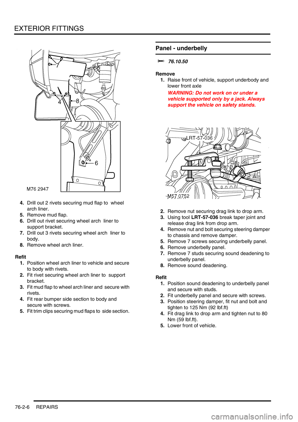
4.Drill out 2 rivets securing mud flap to wheel
arch liner.
5.Remove mud flap.
6.Drill out rivet securing wheel arch liner to
support bracket.
7.Drill out 3 rivets securing wheel arch liner to
body.
8.Remove wheel arch liner.
Refit
1.Position wheel arch liner to vehicle and secure
to body with rivets.
2.Fit rivet securing wheel arch liner to support
bracket.
3.Fit mud flap to wheel arch liner and secure with
rivets.
4.Fit rear bumper side section to body and
secure with screws.
5.Fit trim clips securing mud flaps to side section.
Panel - underbelly
$% 76.10.50
Remove
1.Raise front of vehicle, support underbody and
lower front axle
WARNING: Do not work on or under a
vehicle supported only by a jack. Always
support the vehicle on safety stands.
2.Remove nut securing drag link to drop arm.
3.Using tool LRT-57-036 break taper joint and
release drag link from drop arm.
4.Remove nut and bolt securing steering damper
to chassis and remove damper.
5.Remove 7 screws securing underbelly panel.
6.Remove underbelly panel.
7.Remove 7 studs securing sound deadening to
underbelly panel.
8.Remove sound deadening.
Refit
1.Position sound deadening to underbelly panel
and secure with studs.
2.Fit underbelly panel and secure with screws.
3.Position steering damper, fit nut and bolt and
tighten to 125 Nm (92 lbf.ft)
4.Fit drag link to drop arm and tighten nut to 80
Nm (59 lbf.ft).
5.Lower front of vehicle.
Page 1162 of 1672
INTERIOR TRIM COMPONENTS
REPAIRS 76-3-9
16.Remove console.
NOTE: Do not carry out further dismantling if
component is removed for access only.
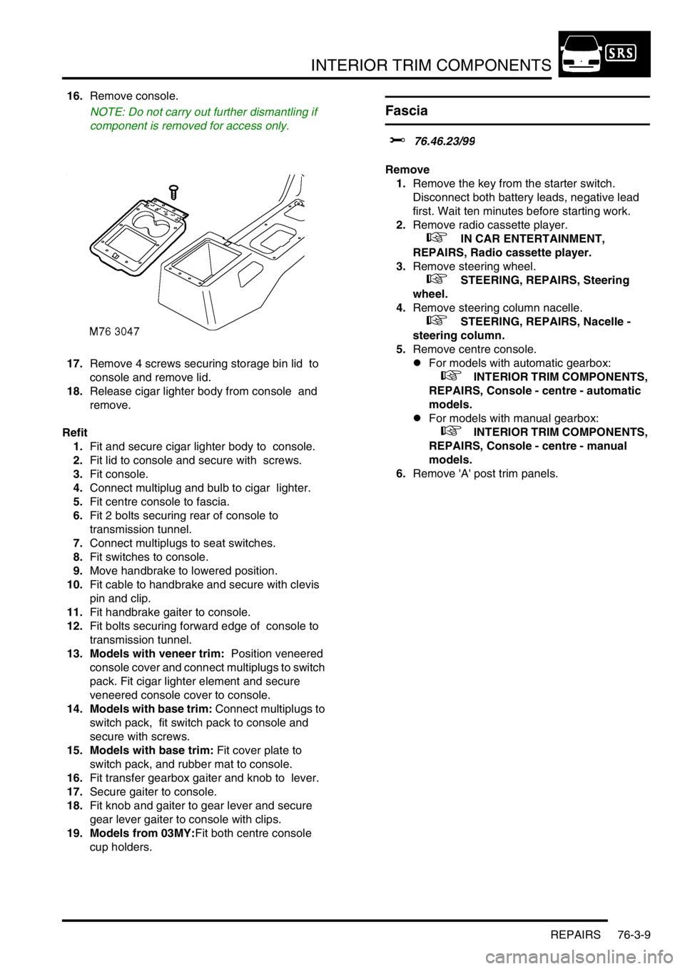
17.Remove 4 screws securing storage bin lid to
console and remove lid.
18.Release cigar lighter body from console and
remove.
Refit
1.Fit and secure cigar lighter body to console.
2.Fit lid to console and secure with screws.
3.Fit console.
4.Connect multiplug and bulb to cigar lighter.
5.Fit centre console to fascia.
6.Fit 2 bolts securing rear of console to
transmission tunnel.
7.Connect multiplugs to seat switches.
8.Fit switches to console.
9.Move handbrake to lowered position.
10.Fit cable to handbrake and secure with clevis
pin and clip.
11.Fit handbrake gaiter to console.
12.Fit bolts securing forward edge of console to
transmission tunnel.
13. Models with veneer trim: Position veneered
console cover and connect multiplugs to switch
pack. Fit cigar lighter element and secure
veneered console cover to console.
14. Models with base trim: Connect multiplugs to
switch pack, fit switch pack to console and
secure with screws.
15. Models with base trim: Fit cover plate to
switch pack, and rubber mat to console.
16.Fit transfer gearbox gaiter and knob to lever.
17.Secure gaiter to console.
18.Fit knob and gaiter to gear lever and secure
gear lever gaiter to console with clips.
19. Models from 03MY:Fit both centre console
cup holders.
Fascia
$% 76.46.23/99
Remove
1.Remove the key from the starter switch.
Disconnect both battery leads, negative lead
first. Wait ten minutes before starting work.
2.Remove radio cassette player.
+ IN CAR ENTERTAINMENT,
REPAIRS, Radio cassette player.
3.Remove steering wheel.
+ STEERING, REPAIRS, Steering
wheel.
4.Remove steering column nacelle.
+ STEERING, REPAIRS, Nacelle -
steering column.
5.Remove centre console.
lFor models with automatic gearbox:
+ INTERIOR TRIM COMPONENTS,
REPAIRS, Console - centre - automatic
models.
lFor models with manual gearbox:
+ INTERIOR TRIM COMPONENTS,
REPAIRS, Console - centre - manual
models.
6.Remove 'A' post trim panels.
Page 1163 of 1672
INTERIOR TRIM COMPONENTS
76-3-10 REPAIRS
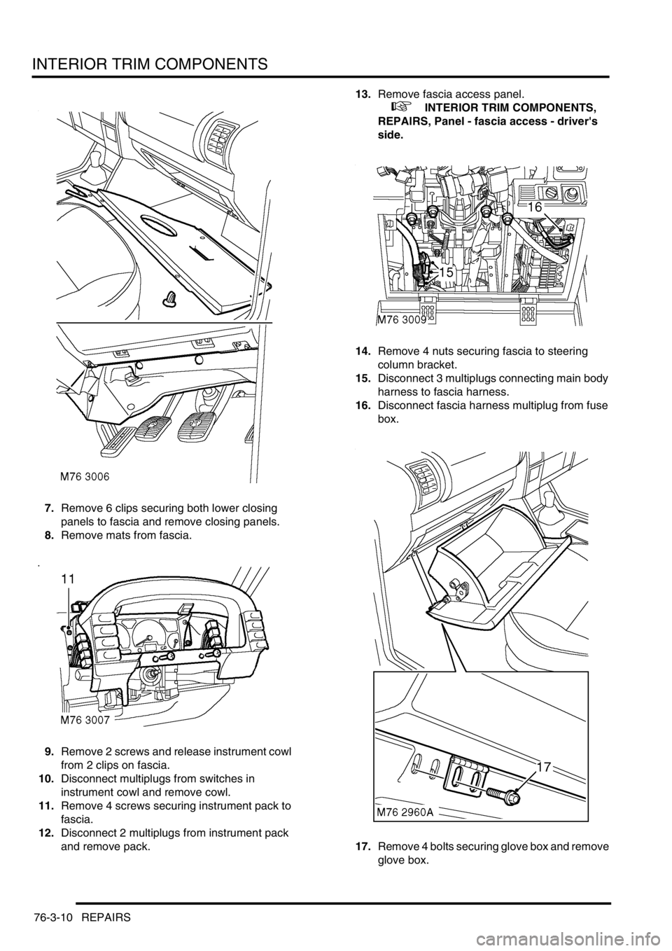
7.Remove 6 clips securing both lower closing
panels to fascia and remove closing panels.
8.Remove mats from fascia.
9.Remove 2 screws and release instrument cowl
from 2 clips on fascia.
10.Disconnect multiplugs from switches in
instrument cowl and remove cowl.
11.Remove 4 screws securing instrument pack to
fascia.
12.Disconnect 2 multiplugs from instrument pack
and remove pack. 13.Remove fascia access panel.
+ INTERIOR TRIM COMPONENTS,
REPAIRS, Panel - fascia access - driver's
side.
14.Remove 4 nuts securing fascia to steering
column bracket.
15.Disconnect 3 multiplugs connecting main body
harness to fascia harness.
16.Disconnect fascia harness multiplug from fuse
box.
17.Remove 4 bolts securing glove box and remove
glove box.
Page 1165 of 1672
INTERIOR TRIM COMPONENTS
76-3-12 REPAIRS
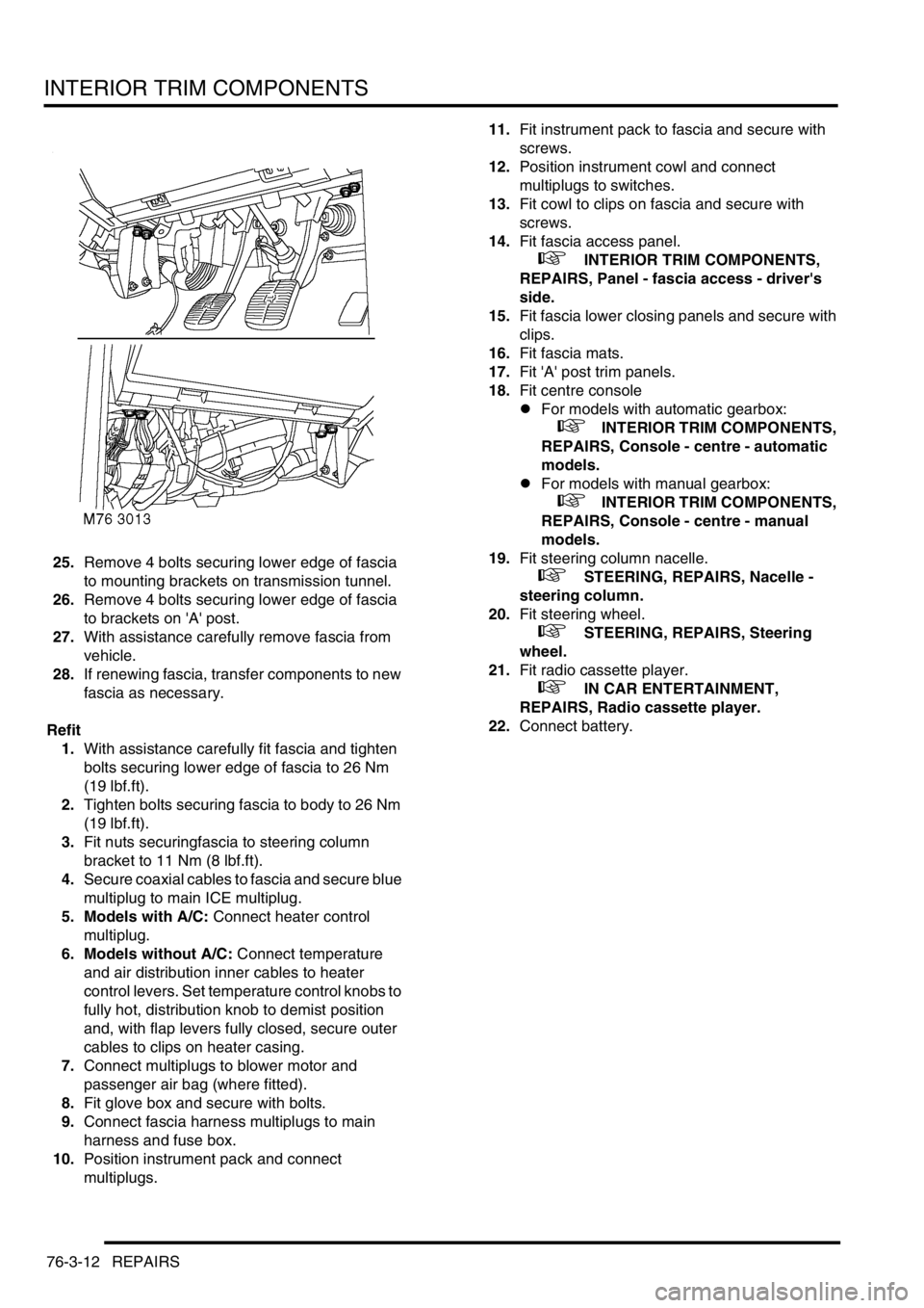
25.Remove 4 bolts securing lower edge of fascia
to mounting brackets on transmission tunnel.
26.Remove 4 bolts securing lower edge of fascia
to brackets on 'A' post.
27.With assistance carefully remove fascia from
vehicle.
28.If renewing fascia, transfer components to new
fascia as necessary.
Refit
1.With assistance carefully fit fascia and tighten
bolts securing lower edge of fascia to 26 Nm
(19 lbf.ft).
2.Tighten bolts securing fascia to body to 26 Nm
(19 lbf.ft).
3.Fit nuts securingfascia to steering column
bracket to 11 Nm (8 lbf.ft).
4.Secure coaxial cables to fascia and secure blue
multiplug to main ICE multiplug.
5. Models with A/C: Connect heater control
multiplug.
6. Models without A/C: Connect temperature
and air distribution inner cables to heater
control levers. Set temperature control knobs to
fully hot, distribution knob to demist position
and, with flap levers fully closed, secure outer
cables to clips on heater casing.
7.Connect multiplugs to blower motor and
passenger air bag (where fitted).
8.Fit glove box and secure with bolts.
9.Connect fascia harness multiplugs to main
harness and fuse box.
10.Position instrument pack and connect
multiplugs.11.Fit instrument pack to fascia and secure with
screws.
12.Position instrument cowl and connect
multiplugs to switches.
13.Fit cowl to clips on fascia and secure with
screws.
14.Fit fascia access panel.
+ INTERIOR TRIM COMPONENTS,
REPAIRS, Panel - fascia access - driver's
side.
15.Fit fascia lower closing panels and secure with
clips.
16.Fit fascia mats.
17.Fit 'A' post trim panels.
18.Fit centre console
lFor models with automatic gearbox:
+ INTERIOR TRIM COMPONENTS,
REPAIRS, Console - centre - automatic
models.
lFor models with manual gearbox:
+ INTERIOR TRIM COMPONENTS,
REPAIRS, Console - centre - manual
models.
19.Fit steering column nacelle.
+ STEERING, REPAIRS, Nacelle -
steering column.
20.Fit steering wheel.
+ STEERING, REPAIRS, Steering
wheel.
21.Fit radio cassette player.
+ IN CAR ENTERTAINMENT,
REPAIRS, Radio cassette player.
22.Connect battery.
Page 1283 of 1672

PANEL REPAIRS
77-2-34 REPAIRS
Refit
1.Fit windscreen side finisher.
+ EXTERIOR FITTINGS, REPAIRS,
Side finisher - windscreen.
2.Fit insulation pad to engine bulkhead.
3.Fit front mud flap.
4.Fit road wheel and tighten nuts to 140 Nm (103
lbf.ft).
5.Fit wiring harness to valance assembly.
6. Models with A/C: Fit A/C pipes to valance
assembly.
7.Fit PAS/ACE reservoir.
8.Fit brake pipes to valance assembly.
9. LHD models: Fit brake servo.
+ BRAKES, REPAIRS, Servo - brake.
10.Fit ABS modulator unit.
+ BRAKES, REPAIRS, Modulator unit
- ABS.
11.Fit front bulkhead assembly.
+ PANEL REPAIRS, REPAIRS, Front
bulkhead assembly.
12.Connect leads/multiplug to alternator.
13.Connect battery leads, negative lead last.
'A' post assembly
In this procedure, the front wing and the valance
outer reinforcement (rear section) are replaced in
conjunction with the 'A' post assembly. The dash side
assembly can also be replaced in this procedure if
required.
Remove
1.Disconnect both battery leads, negative lead
first.
2.Disconnect leads/multiplug from alternator.
3.Remove bonnet.
4.Remove front wing.
+ EXTERIOR FITTINGS, REPAIRS,
Wing - front - up to 03MY.
5.Remove RH or LH front door.
+ DOORS, REPAIRS, Door - front.
6.Remove RH or LH sill finisher.
7.Remove windscreen.
+ SCREENS, REPAIRS, Windscreen.
8. Diesel models: Remove ECM.
+ ENGINE MANAGEMENT SYSTEM -
Td5, REPAIRS, Engine control module
(ECM).
9.Remove RH or LH 'A' post inner finishers and
disconnect speaker multiplug (if fitted).
10.Release sunroof drain tube and position aside.
11.Remove RH or LH front seat.
+ SEATS, REPAIRS, Seat - front.
12. RH side: Remove CD autochanger.
+ IN CAR ENTERTAINMENT,
REPAIRS, CD autochanger.
13.Remove fascia.
+ INTERIOR TRIM COMPONENTS,
REPAIRS, Fascia.
14. Driver's side: Remove steering column
support bracket.
15.Remove relevant wiring from 'A' post.
16.Remove tread plate from front door aperture.
17.Release front carpet and position aside.
18.Remove front door aperture seal.
19.Remove engine bulkhead insulation.
Page 1284 of 1672
PANEL REPAIRS
REPAIRS 77-2-35
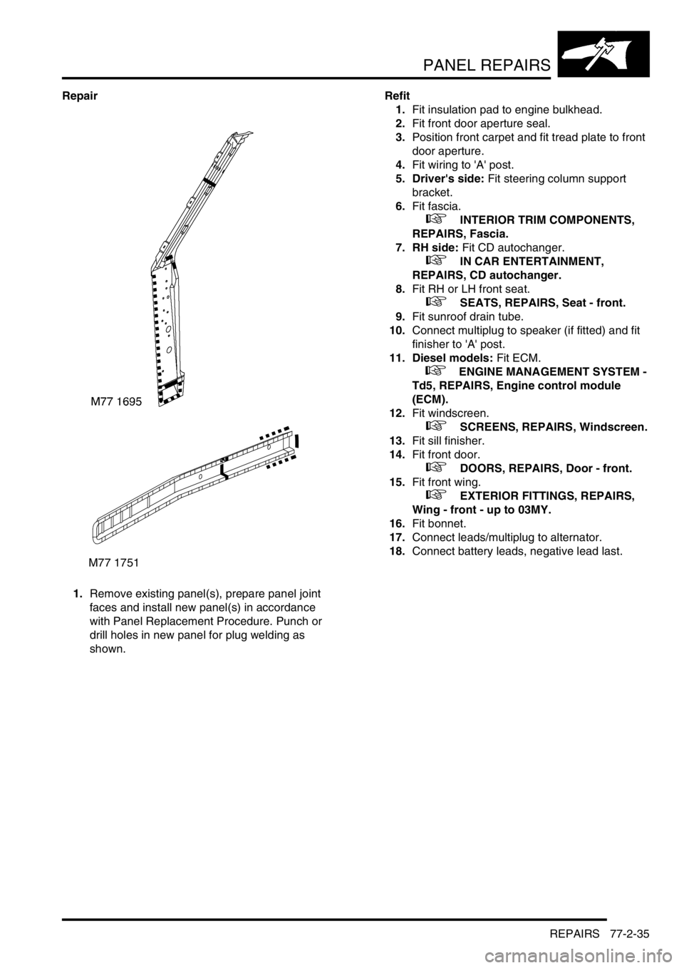
Repair
1.Remove existing panel(s), prepare panel joint
faces and install new panel(s) in accordance
with Panel Replacement Procedure. Punch or
drill holes in new panel for plug welding as
shown.Refit
1.Fit insulation pad to engine bulkhead.
2.Fit front door aperture seal.
3.Position front carpet and fit tread plate to front
door aperture.
4.Fit wiring to 'A' post.
5. Driver's side: Fit steering column support
bracket.
6.Fit fascia.
+ INTERIOR TRIM COMPONENTS,
REPAIRS, Fascia.
7. RH side: Fit CD autochanger.
+ IN CAR ENTERTAINMENT,
REPAIRS, CD autochanger.
8.Fit RH or LH front seat.
+ SEATS, REPAIRS, Seat - front.
9.Fit sunroof drain tube.
10.Connect multiplug to speaker (if fitted) and fit
finisher to 'A' post.
11. Diesel models: Fit ECM.
+ ENGINE MANAGEMENT SYSTEM -
Td5, REPAIRS, Engine control module
(ECM).
12.Fit windscreen.
+ SCREENS, REPAIRS, Windscreen.
13.Fit sill finisher.
14.Fit front door.
+ DOORS, REPAIRS, Door - front.
15.Fit front wing.
+ EXTERIOR FITTINGS, REPAIRS,
Wing - front - up to 03MY.
16.Fit bonnet.
17.Connect leads/multiplug to alternator.
18.Connect battery leads, negative lead last.
M77 1751
Page 1390 of 1672

AIR CONDITIONING
DESCRIPTION AND OPERATION 82-17
RH temperature. Illuminates to show the RH temperature selection, external air temperature or diagnostic fault code.
Blower speed. Illuminates when the blower speed is manually selected. Also illuminates in the automatic modes when
one of the temperatures is set to LO or HI.
External air temperature. EXT illuminates to show that external air temperature is selected on.
All temperature indications on the display are in either
°C or °F. For 1 second after the system is first switched on, the
display shows only
°C or °F, in the LH temperature window, to indicate which temperature scale is in use. After 1
second, the
°C or °F indication goes off and the display shows all relevant outputs.
Temperature conversion: While the system is on, the temperature indications on the display can be switched between
the two scales by pressing and holding the fresh/recirculated air switch, then pressing and holding the A/C on/off
switch until the audible warning sounds (approximately 3 seconds).
Dual pressure switch
The dual pressure switch protects the refrigerant system from extremes of pressure. The normally closed switch is
installed in the top of the receiver drier. If minimum or maximum pressure limits are exceeded the switch contacts
open, causing the compressor clutch to be disengaged. The minimum pressure limit protects the compressor, by
preventing operation of the system unless there is a minimum refrigerant pressure (and thus refrigerant and
lubricating oil) in the system. The maximum pressure limit keeps the refrigerant system within a safe operating
pressure.
Dual pressure switch nominal operating pressures
Evaporator temperature sensor
The evaporator temperature sensor is an encapsulated thermistor that provides the ATC ECU with an input of the
evaporator air outlet temperature. The evaporator temperature sensor is installed in a clip which locates in the
evaporator matrix in the heater assembly. The ATC ECU uses the input to prevent the formation of ice on the
evaporator.
In-car temperature sensor
The in-car temperature sensor is an encapsulated thermistor that provides the ATC ECU with an input of cabin air
temperature. The sensor is integrated into the inlet of an electric fan, which is installed behind a grille in the fascia
outboard of the steering column. The fan runs continuously, while the ignition is on, to draw air through the grille and
across the sensor.
Sunlight sensor
The sunlight sensor consists of two diodes that provide the ATC ECU with inputs of light intensity, one as sensed
coming from the left of the vehicle and one as sensed coming from the right. The inputs are used as a measure of the
solar heating effect on vehicle occupants. The sensor is installed in the centre of the fascia upper surface.
Heater coolant temperature sensor
The heater coolant temperature sensor is an encapsulated thermistor that provides the ATC ECU with an input related
to heater matrix coolant temperature. The sensor is installed in the casing of the heater assembly and presses against
the end tank of the heater matrix.
Ambient temperature sensor
The ambient temperature sensor is an encapsulated thermistor that provides the ATC ECU with an input of external
air temperature. The sensor is attached to the cooling fan mounting bracket in front of the condenser.
Limit Opening pressure, bar (lbf.in2) Closing pressure, bar (lbf.in2)
Minimum 2.0 (29.0), pressure decreasing 2.3 (33.4), pressure increasing
Maximum 32 (464), pressure increasing 26 (377), pressure decreasing
Page 1429 of 1672

WIPERS AND WASHERS
84-8 DESCRIPTION AND OPERATION
Description
General
All markets have a common wiper system with headlamp powerwash as an option.
The wipers system comprises two front wipers and one rear wiper which are powered by electric motors. A washer
reservoir is located in the front left hand wheel arch and is fitted with two electric pumps. Each pump supplies washer
fluid to either the front or rear screens. On certain models, a third pump can be fitted to operate a headlamp power
wash function. Operation of the front and rear wipers and washers is controlled by the driver using switches located
on a steering column stalk and push button switches on the fascia.
Control of the wipers and washers is achieved by the following components:
lBCU.
lIDM.
lFront wiper relay.
lFront wash/ wipe switch.
lVariable delay switch.
lFront wiper motor assembly.
lFront washer pump motor.
lRear wiper relay.
lRear wiper switch.
lRear washer switch.
lRear wiper motor.
lRear washer pump motor.
Both the Body Control Unit (BCU) and the Intelligent Driver Module (IDM) control the wiper system. The BCU controls
the time delay function of the wiper system and is located below and behind the passenger glovebox. During engine
cranking the BCU prevents wiper functions. Two relays are located in the passenger compartment fusebox. The
relays control the delay operation of the front and rear wipers. The relays are an integral part of the fusebox and
cannot be renewed separately.
Power for the wiper system is supplied by the IDM, which is integral with the passenger fusebox and cannot be
renewed as a component. A serial communication link allows communication between the IDM and the BCU.
The system has diagnostic capabilities through TestBook.
Front wipers
The two front windscreen wipers are operated by a linkage assembly and an electric motor located under the plenum
grill below the windscreen. The linkage and motor assembly is handed for left and right hand drive vehicles. The motor
is an integral part of the linkage and cannot be replaced separately.
The linkage comprises a pressed steel mounting plate which provides for the attachment of a wheel box at each end.
The mounting plate is secured to the bulkhead with flanged nuts which attach to a stud plate located behind the
bulkhead. A link arm is attached to each wheel box by a short link and secured with circlips. The link arm has an
attachment hole centrally located along its length for the electric motor drive link.
The electric motor is mounted in a recess in the bulkhead below a sealed cover plate. The drive spindle of the motor
protrudes through the cover plate and is fitted with a link. The link is attached to a tapered spline on the motor spindle
and is secured with a lock washer and nut. The opposite end of the link is attached to the central attachment point on
the link arm and secured with a circlip.
Each wheel box has a taper splined shaft which allows for the attachment of the wiper arm which is secured with a
washer and nut. The shaft of each wheel box is passed through a rubber sealed aperture in the plenum. The wiper
arm attachment to the splined shaft has a pivot to which the remainder of the arm is attached. The two parts of the
arm are connected by a spring which controls the pressure of the blade on the screen to a predetermined amount.
Page 1430 of 1672
WIPERS AND WASHERS
DESCRIPTION AND OPERATION 84-9
The wiper blades are attached to the wiper arms with a clips that allow the blade to pivot. Each wiper blade comprises
a number of levers and yokes to which the rubber wiper is attached. The levers and yokes ensure that the pressure
applied by the arm spring is distributed evenly along the full length of the blade. The rubber wiper is held in the yokes
by a pair of stainless steel strips which also contribute to the even distribution of spring pressure along the blade. The
driver's side wiper blade is fitted with an aerofoil which presses the blade onto the screen at high speed. This prevents
the blade from lifting off the screen and maintains the wiping performance.
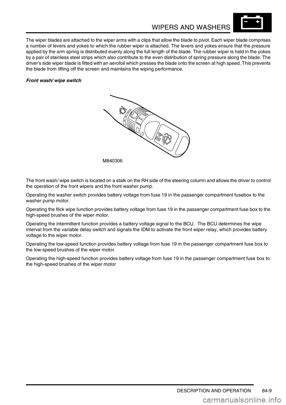
Front wash/ wipe switch
The front wash/ wipe switch is located on a stalk on the RH side of the steering column and allows the driver to control
the operation of the front wipers and the front washer pump.
Operating the washer switch provides battery voltage from fuse 19 in the passenger compartment fusebox to the
washer pump motor.
Operating the flick wipe function provides battery voltage from fuse 19 in the passenger compartment fuse box to the
high-speed brushes of the wiper motor.
Operating the intermittent function provides a battery voltage signal to the BCU. The BCU determines the wipe
interval from the variable delay switch and signals the IDM to activate the front wiper relay, which provides battery
voltage to the wiper motor.
Operating the low-speed function provides battery voltage from fuse 19 in the passenger compartment fuse box to
the low-speed brushes of the wiper motor.
Operating the high-speed function provides battery voltage from fuse 19 in the passenger compartment fuse box to
the high-speed brushes of the wiper motor