ignition LAND ROVER DISCOVERY 2002 Workshop Manual
[x] Cancel search | Manufacturer: LAND ROVER, Model Year: 2002, Model line: DISCOVERY, Model: LAND ROVER DISCOVERY 2002Pages: 1672, PDF Size: 46.1 MB
Page 1105 of 1672

RESTRAINT SYSTEMS
75-10 DESCRIPTION AND OPERATION
SRS warning lamp
The SRS warning lamp illuminates for 5 seconds during system readiness check on starting the engine. The SRS
warning lamp extinguishes for one second after the system readiness check is performed. If a fault is present the
warning lamp then illuminates continuously. If no fault is present, the SRS warning lamp remains extinguished. If a
system fault occurs in excess of two seconds after the readiness check has been completed, the SRS warning lamp
illuminates for that ignition cycle. It remains illuminated for a minimum of 12 seconds
± 4 seconds for all fault
conditions.
The SRS warning lamp will only illuminate for low voltage concerns while the low voltage condition is present. If the
low voltage condition is corrected, the SRS warning lamp extinguishes and the fault is recorded in the DCU's memory.
Page 1188 of 1672

SEATS
DESCRIPTION AND OPERATION 76-5-3
1Ignition switch
2BCU
3Driver door switch
4Left seat power relay
5Left seat satellite fuse box
6Left seat switch pack
7Left seat fore/ aft motor
8Left seat cushion front up/ down motor
9Left seat cushion rear up/ down motor
10Left seat squab fore/ aft motor
11Left seat lumbar pump
12Left seat lumbar deflate solenoid
13Right seat power relay
14Right seat satellite fuse box
15Right seat switch pack
16Right seat fore/ aft motor
17Right seat cushion front up/ down motor
18Right seat cushion rear up/ down motor
19Right seat squab fore/ aft motor
20Right seat lumbar pump
21Right seat lumbar deflate solenoid
22Passenger front door switch
Page 1192 of 1672

SEATS
DESCRIPTION AND OPERATION 76-5-7
Operation - electric seats
Seat power relay enable line
The BCU provides the seat power relays with an earth supply to the relay coil that enables the relay operation. When
this seat power relay enable line is active, the seat power relay energises allowing seat operation.
In order for the seat power relay to be active the BCU must detect either of the following condition options:
lIgnition switch in position II.
lIgnition switch in position II or driver's door within 45 seconds of opening.
Seat fore/ aft movement
When the cushion switch is operated and the seat power relay enable line is operating, power and earth are supplied
to the motor in the seat, allowing the seat to move forward or backward depending on switch position. The motor
drives a gear wheel along a gear rack connected to the seat base. Sliding the cushion switch forward causes the motor
to drive the seat forward. Sliding the cushion switch rearward reverses polarity of the voltage at the seat motor, driving
the seat rearward.
Seat cushion front up/ down movement
When the cushion switch is operated and the seat power relay enable line is operating, power and earth are supplied
to the motor in the seat, allowing the front of the seat cushion to move upward or downward depending on switch
position. The motor drives a gear wheel along a gear rack connected to the seat base. Sliding the front of the cushion
switch upward causes the motor to drive the seat upward. Sliding the front of the cushion switch downward reverses
polarity of the voltage at the seat motor driving the seat downward.
Seat cushion rear up/ down movement
When the cushion switch is operated and the seat power relay enable line is operating, power and earth are supplied
to the motor in the seat, allowing the seat to move upwards or downwards depending on switch position. The motor
drives a gear wheel along a gear rack connected to the seat base. Sliding the rear of the cushion switch upward
causes the motor to drive the seat upward. Sliding the rear of the cushion switch downward reverses polarity of the
voltage at the seat motor driving the seat downward.
Squab fore/ aft movement
When the squab switch is operated and the seat power relay enable line is operating, power and earth is supplied to
the motor in the squab, allowing the squab to move forward or backward depending on switch position. The motor
drives a gear wheel along a rotary gear rack connected to the squab. Sliding the squab switch forward causes the
motor to drive the squab forward. Sliding the squab switch rearward reverses polarity of the voltage at the seat motor
driving the squab rearward.
Lumbar inflate/ deflate
Sliding the squab switch upwards when the seat power relay enable line is operating applies voltage to the lumbar
pump. The lumbar pump inflates the lumbar bladder, increasing lumbar support. The lumbar pump and the normally
closed lumbar deflate solenoid hold the air in the bladder. Sliding the squab switch downwards applies voltage to the
deflate solenoid, venting the air in the lumbar bladder to atmosphere, decreasing lumbar support.
Diagnostics
TestBook can only verify that the seat power relay line is enabled. It cannot determine the status of the system or any
of the components.
Page 1196 of 1672

SEATS
DESCRIPTION AND OPERATION 76-5-11
Description - heated seats
Heated seats
The heated seat system is available on both manual seats and electric seats. The electrical sub-system consists of
the following components:
lSeat heater switches.
lSeat heater elements.
lTemperature control unit (if electric seats are fitted).
lTemperature sensor (if electric seats are fitted).
lThermostat (if manual seats are fitted).
Seat heater switches
The seat heater switches supply an ignition feed to either the temperature control unit (vehicles with electric seats) or
directly to the seat heater elements (vehicles with manual seats). When a seat heater switch is operated, current flows
to the seat heater elements causing them to heat the seat.
The ignition feed comes from fuse 15 in the passenger compartment fuse box.
Seat heater elements
The seat heater elements are located in the seat cushion and squab. The cushion and squab heater elements are
wired in series. Total power consumption at 13.5 volts is approximately 115 Watts.
The cushion heater element has an input feed from the temperature control unit or heater switch and an output to the
squab heater element, which outputs to earth.
Page 1197 of 1672

SEATS
76-5-12 DESCRIPTION AND OPERATION
Temperature control unit
The temperature control unit is only fitted to vehicles with electric seats. Feed back of the seat temperature is via a
Negative Temperature Coefficient (NTC) sensor within the seat cushion. Resistance of this sensor changes with the
temperature of the seat cushion allowing the temperature control unit to lower or raise the voltage to the seat heater
elements to raise or lower their temperature.
An ignition feed is supplied via the seat heater switch. The temperature sensor supplies an input. Output is a supply
to the cushion heater element and an earth.
Thermostat
On vehicles with non electric seats, the temperature is controlled by a thermostat located in the seat cushion. The
thermostat interrupts the power supply when it reaches a pre-determined temperature.
Page 1220 of 1672

SUNROOF
DESCRIPTION AND OPERATION 76-6-5
Description
General
The sunroof system consists of a front and a rear sunroof assembly. Both sunroof assemblies slide and tilt to open.
The sunroof system consists of the following components:
lSunroof ECU.
lBCU.
lFront sunroof switch.
lFront sunroof motor and microswitch.
lRear sunroof - front switch.
lRear sunroof - rear switch.
lRear sunroof isolation switch.
lRear sunroof motor and microswitch.
The BCU enables operation of the sunroof ECU. If the sunroof ECU does not receive an enable signal from the BCU,
neither sunroof assembly operates. The BCU is located behind the glovebox. The sunroof ECU is located above the
headlining next to the front sunroof assembly.
TestBook diagnoses the sunroof ECU.
Front sunroof switch
The front sunroof switch is located in the roof console above the windscreen in front of the front sunroof. It controls
the front sunroof motor via the sunroof ECU.
The front sunroof switch supplies an earth signal to the sunroof ECU. The pin at the ECU that receives the earth
signal determines whether ECU causes the sunroof to open or close.
TestBook cannot monitor the state of the front sunroof switch.
The following table lists the values which can be measured at the listed ECU pins when the conditions outlined are
met:
Signal values (connector connected)
Connector/Pin
No.Condition Resistance, ohms
C0784-2 Ignition in position II, front sunroof switch released > 10,000
C0784-2 Ignition in position II, front sunroof switch open < 0.5
C0785-7 Ignition in position II, front sunroof switch released > 10,000
C0785-7 Ignition in position II, front sunroof switch closed < 0.5
Page 1221 of 1672

SUNROOF
76-6-6 DESCRIPTION AND OPERATION
Front sunroof motor and microswitch
The front sunroof motor is located within the front sunroof assembly. The sunroof ECU controls the front sunroof
motor.
The sunroof ECU determines the direction the sunroof motor runs. A battery signal to one side of the motor and an
earth to the other side of the motor causes the motor to turn in one direction, reversing the polarity through the same
pins causes the motor to turn in the opposite direction.
The following table lists the values which can be measured at the listed ECU pins when the conditions outlined are
met:
Signal values (connector connected)
Connector/Pin
No.Condition Voltage Resistance, ohms
C0785-5 Ignition in position II, rear of front sunroof switch
pressed+voltage to C0785-
5
C0785-1 Ignition in position II, front of front sunroof switch
pressed+voltage to C0785-
1< 0.5
C0784-8 Ignition in position II, sunroof fully closed +V Batt
C0784-8 Ignition in position II, sunroof not closed > 10,0000
Page 1222 of 1672

SUNROOF
DESCRIPTION AND OPERATION 76-6-7
Rear sunroof - front switch
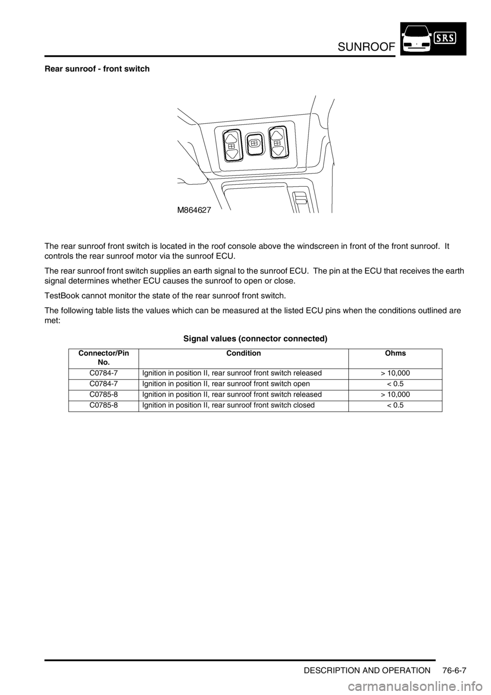
The rear sunroof front switch is located in the roof console above the windscreen in front of the front sunroof. It
controls the rear sunroof motor via the sunroof ECU.
The rear sunroof front switch supplies an earth signal to the sunroof ECU. The pin at the ECU that receives the earth
signal determines whether ECU causes the sunroof to open or close.
TestBook cannot monitor the state of the rear sunroof front switch.
The following table lists the values which can be measured at the listed ECU pins when the conditions outlined are
met:
Signal values (connector connected)
Connector/Pin
No.Condition Ohms
C0784-7 Ignition in position II, rear sunroof front switch released > 10,000
C0784-7 Ignition in position II, rear sunroof front switch open < 0.5
C0785-8 Ignition in position II, rear sunroof front switch released > 10,000
C0785-8 Ignition in position II, rear sunroof front switch closed < 0.5
Page 1223 of 1672

SUNROOF
76-6-8 DESCRIPTION AND OPERATION
Rear sunroof isolation switch
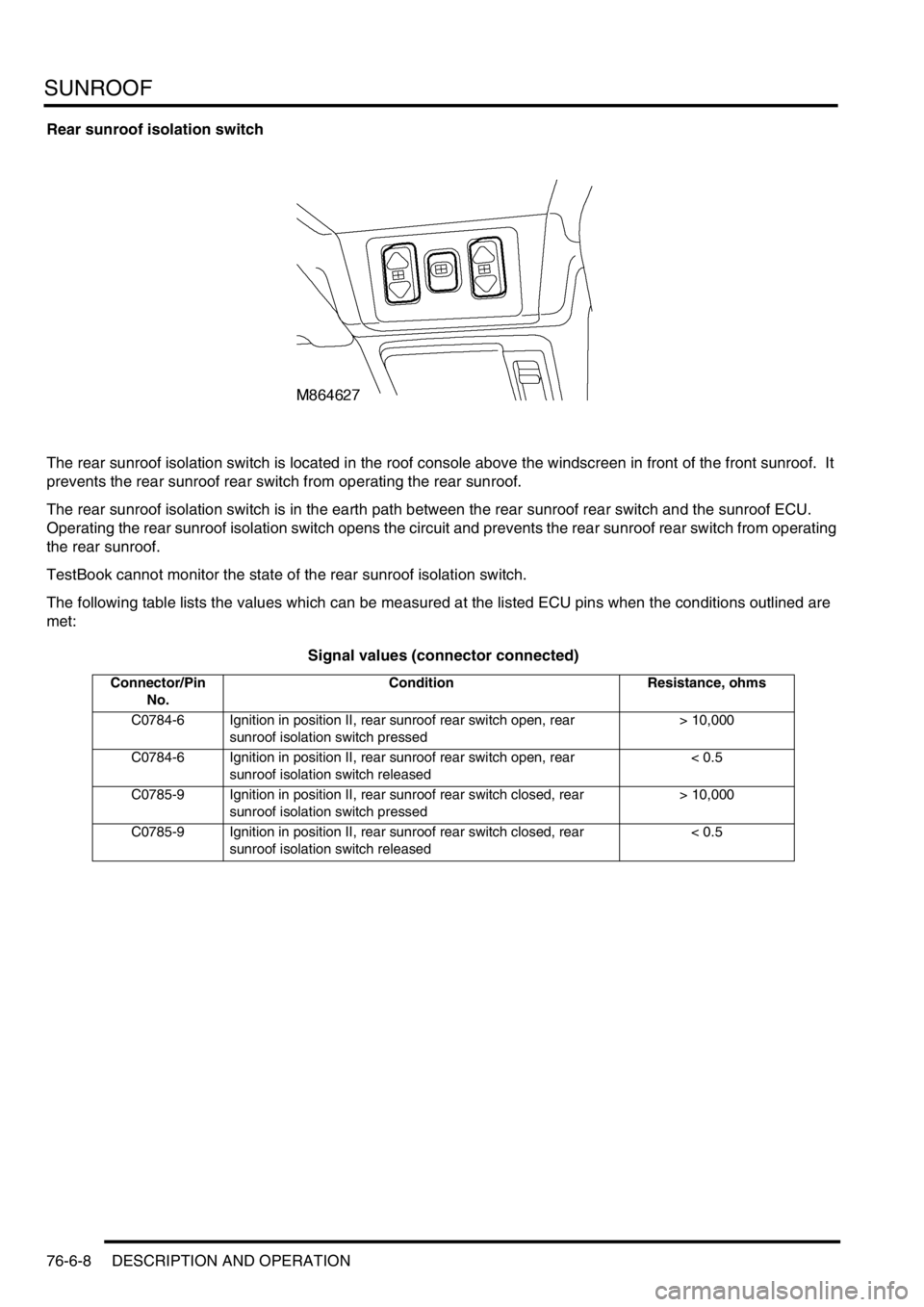
The rear sunroof isolation switch is located in the roof console above the windscreen in front of the front sunroof. It
prevents the rear sunroof rear switch from operating the rear sunroof.
The rear sunroof isolation switch is in the earth path between the rear sunroof rear switch and the sunroof ECU.
Operating the rear sunroof isolation switch opens the circuit and prevents the rear sunroof rear switch from operating
the rear sunroof.
TestBook cannot monitor the state of the rear sunroof isolation switch.
The following table lists the values which can be measured at the listed ECU pins when the conditions outlined are
met:
Signal values (connector connected)
Connector/Pin
No.Condition Resistance, ohms
C0784-6 Ignition in position II, rear sunroof rear switch open, rear
sunroof isolation switch pressed> 10,000
C0784-6 Ignition in position II, rear sunroof rear switch open, rear
sunroof isolation switch released< 0.5
C0785-9 Ignition in position II, rear sunroof rear switch closed, rear
sunroof isolation switch pressed> 10,000
C0785-9 Ignition in position II, rear sunroof rear switch closed, rear
sunroof isolation switch released< 0.5
Page 1224 of 1672

SUNROOF
DESCRIPTION AND OPERATION 76-6-9
Rear sunroof rear switch
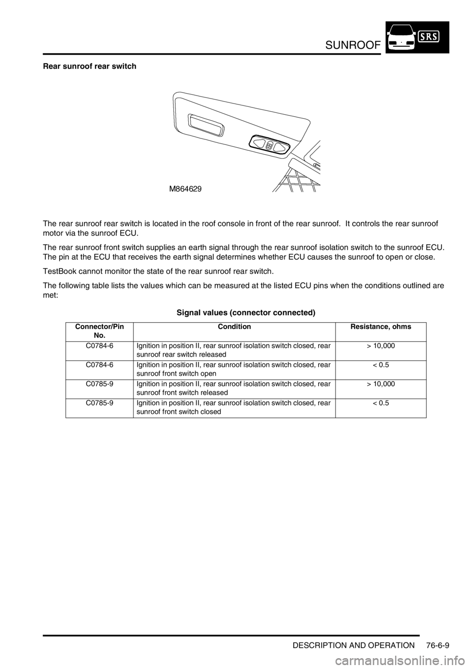
The rear sunroof rear switch is located in the roof console in front of the rear sunroof. It controls the rear sunroof
motor via the sunroof ECU.
The rear sunroof front switch supplies an earth signal through the rear sunroof isolation switch to the sunroof ECU.
The pin at the ECU that receives the earth signal determines whether ECU causes the sunroof to open or close.
TestBook cannot monitor the state of the rear sunroof rear switch.
The following table lists the values which can be measured at the listed ECU pins when the conditions outlined are
met:
Signal values (connector connected)
Connector/Pin
No.Condition Resistance, ohms
C0784-6 Ignition in position II, rear sunroof isolation switch closed, rear
sunroof rear switch released> 10,000
C0784-6 Ignition in position II, rear sunroof isolation switch closed, rear
sunroof front switch open< 0.5
C0785-9 Ignition in position II, rear sunroof isolation switch closed, rear
sunroof front switch released> 10,000
C0785-9 Ignition in position II, rear sunroof isolation switch closed, rear
sunroof front switch closed< 0.5