clock LAND ROVER DISCOVERY 2002 User Guide
[x] Cancel search | Manufacturer: LAND ROVER, Model Year: 2002, Model line: DISCOVERY, Model: LAND ROVER DISCOVERY 2002Pages: 1672, PDF Size: 46.1 MB
Page 212 of 1672
ENGINE - TD5
OVERHAUL 12-1-73
11.Ensure engine is set to TDC firing - No.1
cylinder.
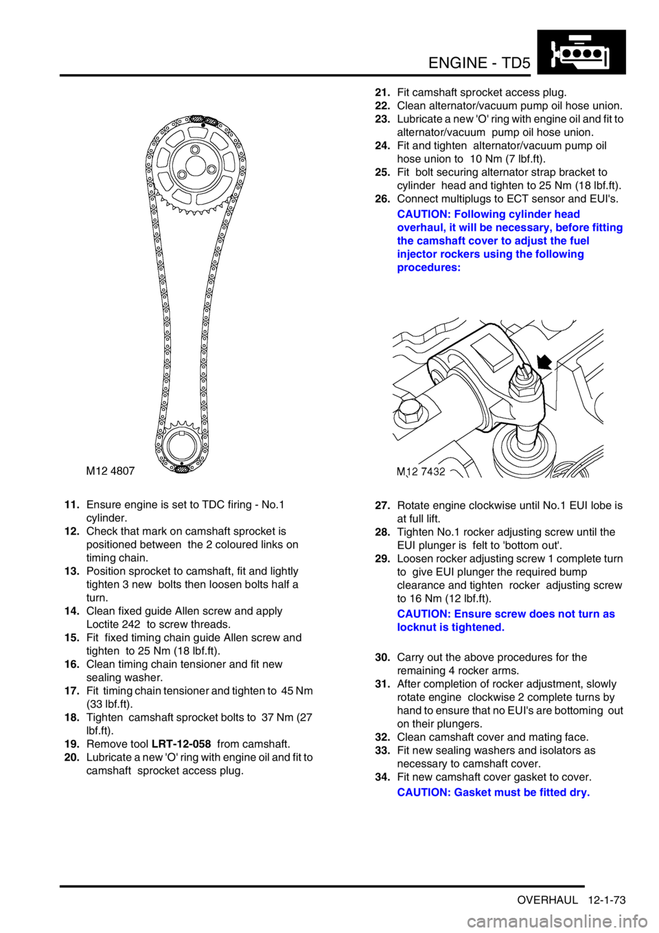
12.Check that mark on camshaft sprocket is
positioned between the 2 coloured links on
timing chain.
13.Position sprocket to camshaft, fit and lightly
tighten 3 new bolts then loosen bolts half a
turn.
14.Clean fixed guide Allen screw and apply
Loctite 242 to screw threads.
15.Fit fixed timing chain guide Allen screw and
tighten to 25 Nm (18 lbf.ft).
16.Clean timing chain tensioner and fit new
sealing washer.
17.Fit timing chain tensioner and tighten to 45 Nm
(33 lbf.ft).
18.Tighten camshaft sprocket bolts to 37 Nm (27
lbf.ft).
19.Remove tool LRT-12-058 from camshaft.
20.Lubricate a new 'O' ring with engine oil and fit to
camshaft sprocket access plug.21.Fit camshaft sprocket access plug.
22.Clean alternator/vacuum pump oil hose union.
23.Lubricate a new 'O' ring with engine oil and fit to
alternator/vacuum pump oil hose union.
24.Fit and tighten alternator/vacuum pump oil
hose union to 10 Nm (7 lbf.ft).
25.Fit bolt securing alternator strap bracket to
cylinder head and tighten to 25 Nm (18 lbf.ft).
26.Connect multiplugs to ECT sensor and EUI's.
CAUTION: Following cylinder head
overhaul, it will be necessary, before fitting
the camshaft cover to adjust the fuel
injector rockers using the following
procedures:
27.Rotate engine clockwise until No.1 EUI lobe is
at full lift.
28.Tighten No.1 rocker adjusting screw until the
EUI plunger is felt to 'bottom out'.
29.Loosen rocker adjusting screw 1 complete turn
to give EUI plunger the required bump
clearance and tighten rocker adjusting screw
to 16 Nm (12 lbf.ft).
CAUTION: Ensure screw does not turn as
locknut is tightened.
30.Carry out the above procedures for the
remaining 4 rocker arms.
31.After completion of rocker adjustment, slowly
rotate engine clockwise 2 complete turns by
hand to ensure that no EUI's are bottoming out
on their plungers.
32.Clean camshaft cover and mating face.
33.Fit new sealing washers and isolators as
necessary to camshaft cover.
34.Fit new camshaft cover gasket to cover.
CAUTION: Gasket must be fitted dry.
Page 233 of 1672
ENGINE - TD5
12-1-94 OVERHAUL
15.Remove bolt and remove timing chain
adjustable guide.
16.Remove bolt and remove timing chain
lubrication jet.
17.Using tool LRT-12-092, remove and discard oil
seal from timing cover.
Inspection
1.Clean all components.
2.Check condition of timing chain running
surfaces on adjustable and fixed guides.
CAUTION: Adjustable guide fitted to Engine
Serial No. Prefixes 15P to 19P may be fitted
to early engines provided that timing chain
tensioner having a YELLOW coloured body
is also fitted.
3.Check timing chains and sprockets for signs of
wear.
CAUTION: Timing chains and sprockets
fitted to Engine Serial No. Prefixes 15P to
19P may be fitted to early engines as an
assembly only, oil pump drive sprockets are
interchangeable. Later timing chains have
BRONZE coloured timing links.
4.Check that drilling in timing chain lubrication jet
is clear.
5.Clean oil seal recess in timing cover and oil seal
running surface on crankshaft.
6.Remove all traces of sealant from mating faces
of timing cover and cylinder block using
suitable solvent.
CAUTION: Do not use metal scrapers.
7.Ensure bolt and dowel holes are clean and dry.
8.Clean oil pump sprocket bolt threads.Reassembly
1.Fit timing chain lubrication jet.
2.Fit timing chain lubrication jet Torx screw and
tighten to 10 Nm (7 lbf.ft).
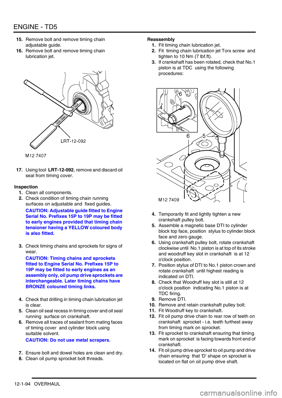
3.If crankshaft has been rotated, check that No.1
piston is at TDC using the following
procedures:
4.Temporarily fit and lightly tighten a new
crankshaft pulley bolt.
5.Assemble a magnetic base DTI to cylinder
block top face, position stylus to cylinder block
face and zero gauge.
6.Using crankshaft pulley bolt, rotate crankshaft
clockwise until No.1 piston is at top of its stroke
and woodruff key slot in crankshaft is at 12
o'clock position.
7.Position stylus of DTI to No.1 piston crown and
rotate crankshaft until highest reading is
indicated on DTI.
8.Check that Woodruff key slot is still at 12
o'clock position indicating No.1 piston is at
TDC firing.
9.Remove DTI.
10.Remove and retain crankshaft pulley bolt.
11.Fit Woodruff key to crankshaft.
12.Fit oil pump drive chain to rear row of teeth on
crankshaft sprocket - i.e. teeth furthest away
from timing mark on sprocket.
13.Fit sprocket to crankshaft ensuring that timing
mark on sprocket is facing towards front end of
crankshaft.
14.Fit oil pump drive sprocket to oil pump and drive
chain ensuring that 'D' shape on sprocket is
located on flat on oil pump drive shaft.
Page 235 of 1672
ENGINE - TD5
12-1-96 OVERHAUL
27.Fit tool LRT-51-003 to crankshaft pulley,
secure with 2 bolts. Using assistance, restrain
engine and using a torque multiplier tighten
bolt to 450 Nm (340 lbf.ft).
WARNING: DUE TO THE HIGH TORQUE
LOADING REQUIRED, IT IS ESSENTIAL
THAT ENGINE IS ADEQUATELY
RESTRAINED.
28.Remove tool LRT-51-003.
29.Position damper to crankshaft pulley, fit 3 bolts
and tighten to 80 Nm (60 lbf.ft).
30.Fit sump gasket.
+ ENGINE - Td5, OVERHAUL, Gasket
- engine sump.
31.Fit cylinder head gasket.
+ ENGINE - Td5, OVERHAUL, Gasket
- cylinder head.
Bearings - connecting rods
$% 12.17.16.01
Disassembly
1.Remove oil pump.
+ ENGINE - Td5, OVERHAUL, Pump -
oil.
2.Mark cylinder reference number on each
connecting rod big-end bearing cap.
3.Make suitable alignment marks between each
big-end bearing cap and connecting rod.
CAUTION: Due to the 'fracture split' method
of manufacturing connecting rods,
incorrect fitment of cap to rod will damage
mating faces and necessitate replacement
of connecting rod assembly.
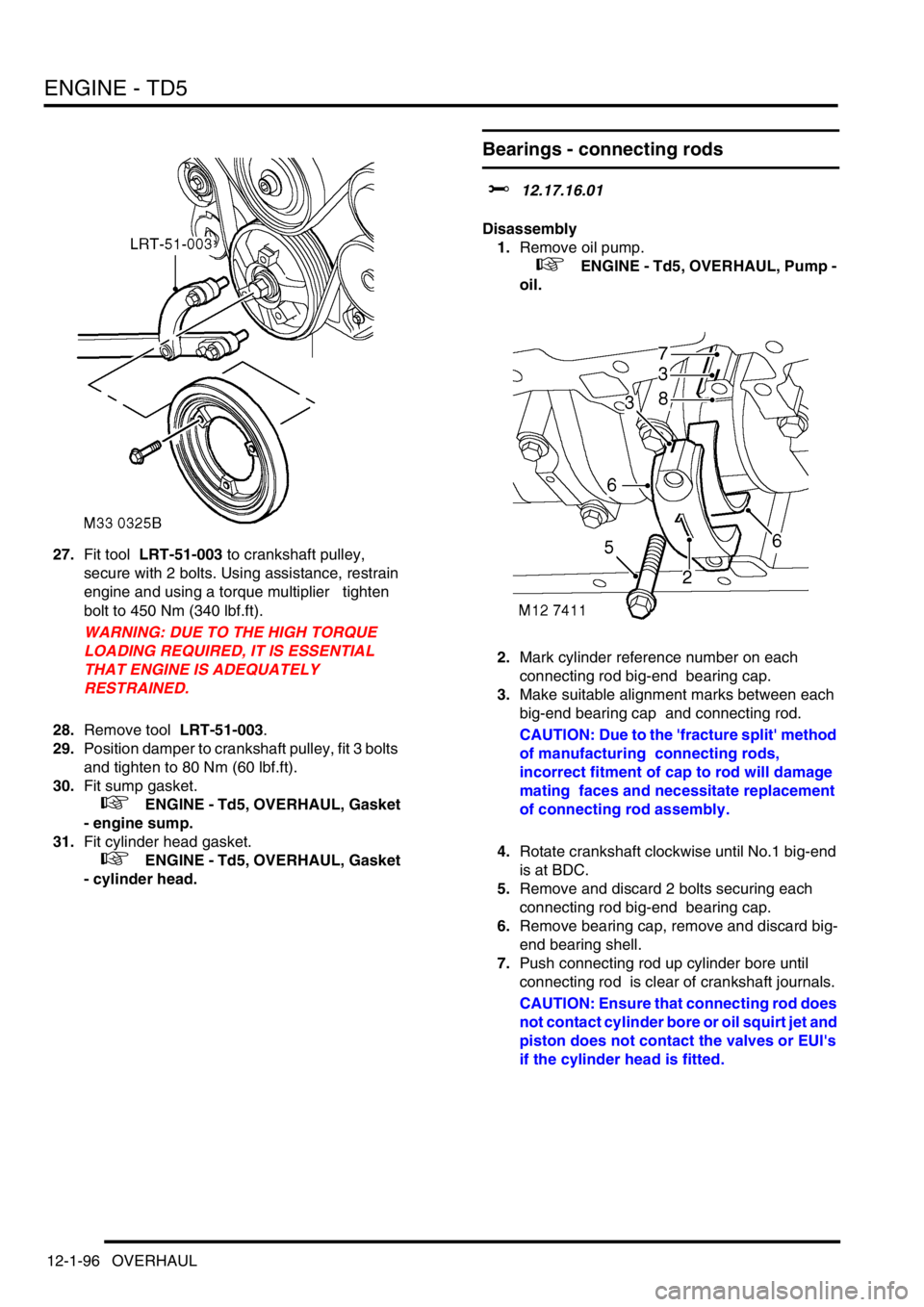
4.Rotate crankshaft clockwise until No.1 big-end
is at BDC.
5.Remove and discard 2 bolts securing each
connecting rod big-end bearing cap.
6.Remove bearing cap, remove and discard big-
end bearing shell.
7.Push connecting rod up cylinder bore until
connecting rod is clear of crankshaft journals.
CAUTION: Ensure that connecting rod does
not contact cylinder bore or oil squirt jet and
piston does not contact the valves or EUI's
if the cylinder head is fitted.
Page 240 of 1672
ENGINE - TD5
OVERHAUL 12-1-101
11.Repeat above procedures for other pistons in
turn ensuring that pistons and connecting rods
are fitted in cylinder bores from which they
were removed.
12.Fit connecting rod bearings.
+ ENGINE - Td5, OVERHAUL,
Bearings - connecting rods.
CAUTION: If new pistons, connecting rods
or crankshaft have been fitted, it will be
necessary to select correct thickness of
cylinder head gasket using the following
procedures:
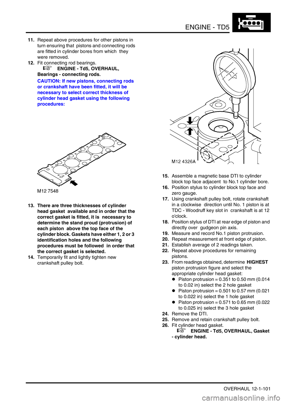
13. There are three thicknesses of cylinder
head gasket available and in order that the
correct gasket is fitted, it is necessary to
determine the stand proud (protrusion) of
each piston above the top face of the
cylinder block. Gaskets have either 1, 2 or 3
identification holes and the following
procedures must be followed in order that
the correct gasket is selected.
14.Temporarily fit and lightly tighten new
crankshaft pulley bolt. 15.Assemble a magnetic base DTI to cylinder
block top face adjacent to No.1 cylinder bore.
16.Position stylus to cylinder block top face and
zero gauge.
17.Using crankshaft pulley bolt, rotate crankshaft
in a clockwise direction until No. 1 piston is at
TDC - Woodruff key slot in crankshaft is at 12
o'clock.
18.Position stylus of DTI at rear edge of piston and
directly over gudgeon pin axis.
19.Measure and record No.1 piston protrusion.
20.Repeat measurement at front edge of piston.
21.Establish average of 2 readings taken.
22.Repeat above procedures for remaining
pistons.
23.From readings obtained, determine HIGHEST
piston protrusion figure and select the
appropriate cylinder head gasket:
lPiston protrusion = 0.351 to 0.50 mm (0.014
to 0.02 in) select the 2 hole gasket
lPiston protrusion = 0.501 to 0.57 mm (0.021
to 0.022 in) select the 1 hole gasket
lPiston protrusion = 0.571 to 0.65 mm (0.022
to 0.025 in) select the 3 hole gasket
24.Remove the DTI.
25.Remove and retain crankshaft pulley bolt.
26.Fit cylinder head gasket.
+ ENGINE - Td5, OVERHAUL, Gasket
- cylinder head.
Page 301 of 1672
ENGINE - V8
12-2-58 OVERHAUL
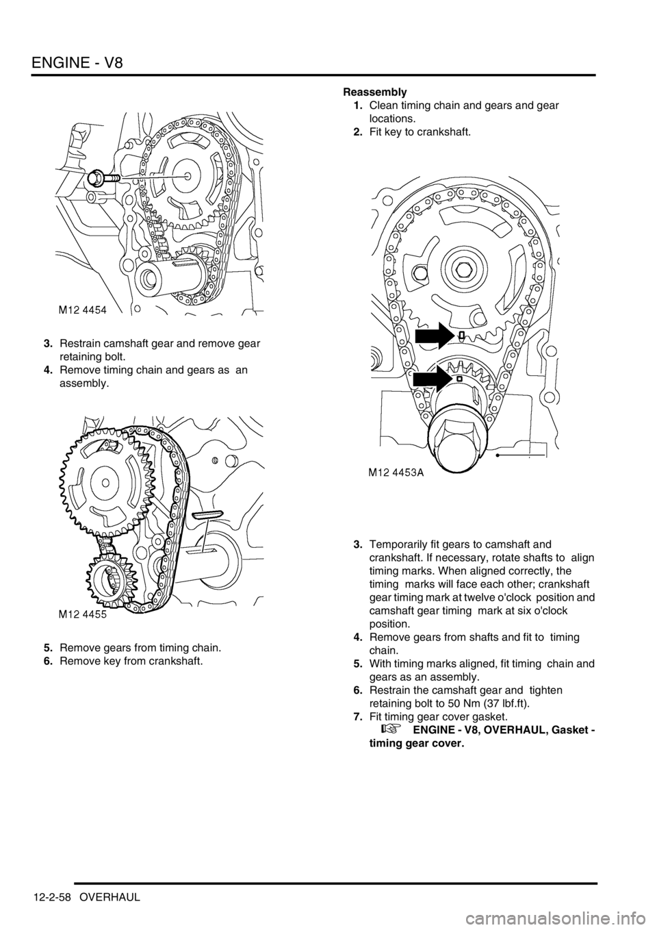
3.Restrain camshaft gear and remove gear
retaining bolt.
4.Remove timing chain and gears as an
assembly.
5.Remove gears from timing chain.
6.Remove key from crankshaft. Reassembly
1.Clean timing chain and gears and gear
locations.
2.Fit key to crankshaft.
3.Temporarily fit gears to camshaft and
crankshaft. If necessary, rotate shafts to align
timing marks. When aligned correctly, the
timing marks will face each other; crankshaft
gear timing mark at twelve o'clock position and
camshaft gear timing mark at six o'clock
position.
4.Remove gears from shafts and fit to timing
chain.
5.With timing marks aligned, fit timing chain and
gears as an assembly.
6.Restrain the camshaft gear and tighten
retaining bolt to 50 Nm (37 lbf.ft).
7.Fit timing gear cover gasket.
+ ENGINE - V8, OVERHAUL, Gasket -
timing gear cover.
Page 303 of 1672
ENGINE - V8
12-2-60 OVERHAUL
Reassembly
1.Reassemble rocker shafts, ensuring that
components are returned to their original
positions, secure plain washers with new split
pins.
2.Ensure shaft identification groove is positioned
at one o'clock, with push rod locations of rocker
arms to the right. Oil feed restriction will
result if rocker shafts are incorrectly
assembled.
3.Position rocker shaft assembly to cylinder
head ensuring push rods are engaged in
rocker arms.
4.Fit rocker shaft bolts and progressively tighten
to 40 Nm (30 lbf.ft).
5.Clean mating faces of rocker covers and
cylinder heads.
6.Fit new rocker cover gaskets, dry, position
rocker cover, fit bolts and working in diagonal
sequence, tighten to:
lStage 1 - 3 Nm (2.5 lbf.ft)
lStage 2 - 8 Nm (6 lbf.ft)
7.Ensure that gasket is correctly positioned
around periphery of rocker cover.
8.Secure ht leads to rocker cover.
Gasket - cylinder head
$% 12.29.02.01
Disassembly
1.Remove inlet manifold gasket.
+ ENGINE - V8, OVERHAUL, Gasket -
inlet manifold.
2. RH cylinder head: Remove auxiliary drive belt
tensioner.
3. RH cylinder head: Remove bolts securing
alternator mounting bracket and remove
bracket.
4.Noting their fitted order, disconnect ht leads
from spark plugs.
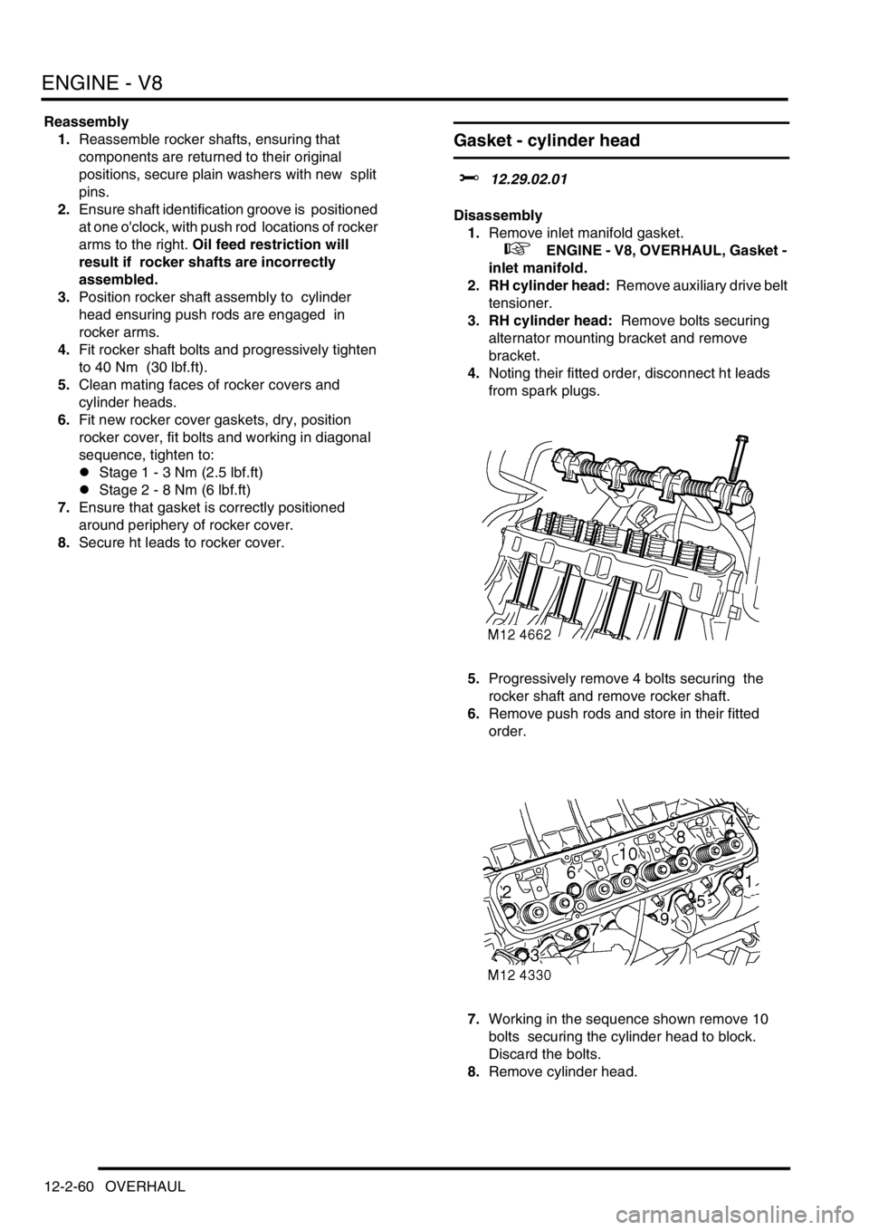
5.Progressively remove 4 bolts securing the
rocker shaft and remove rocker shaft.
6.Remove push rods and store in their fitted
order.
7.Working in the sequence shown remove 10
bolts securing the cylinder head to block.
Discard the bolts.
8.Remove cylinder head.
Page 821 of 1672
AUTOMATIC GEARBOX - ZF4HP22 - 24
44-24 REPAIRS
Selector indicator
$% 44.15.10
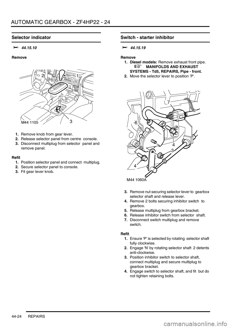
Remove
1.Remove knob from gear lever.
2.Release selector panel from centre console.
3.Disconnect multiplug from selector panel and
remove panel.
Refit
1.Position selector panel and connect multiplug.
2.Secure selector panel to console.
3.Fit gear lever knob.
Switch - starter inhibitor
$% 44.15.19
Remove
1. Diesel models: Remove exhaust front pipe.
+ MANIFOLDS AND EXHAUST
SYSTEMS - Td5, REPAIRS, Pipe - front.
2.Move the selector lever to position 'P'.
3.Remove nut securing selector lever to gearbox
selector shaft and release lever.
4.Remove 2 bolts securing inhibitor switch to
gearbox.
5.Release multiplug from gearbox bracket.
6.Release inhibitor switch from selector shaft.
7.Disconnect switch multiplug and remove
switch.
Refit
1.Ensure 'P' is selected by rotating selector shaft
fully clockwise.
2.Engage 'N' by rotating selector shaft 2 detents
anti-clockwise.
3.Position inhibitor switch to selector shaft,
connect multiplug and secure multiplug to
gearbox bracket.
4.Engage switch to selector shaft, and fit but do
not tighten retaining bolts.
Page 982 of 1672
FRONT SUSPENSION
REPAIRS 60-43
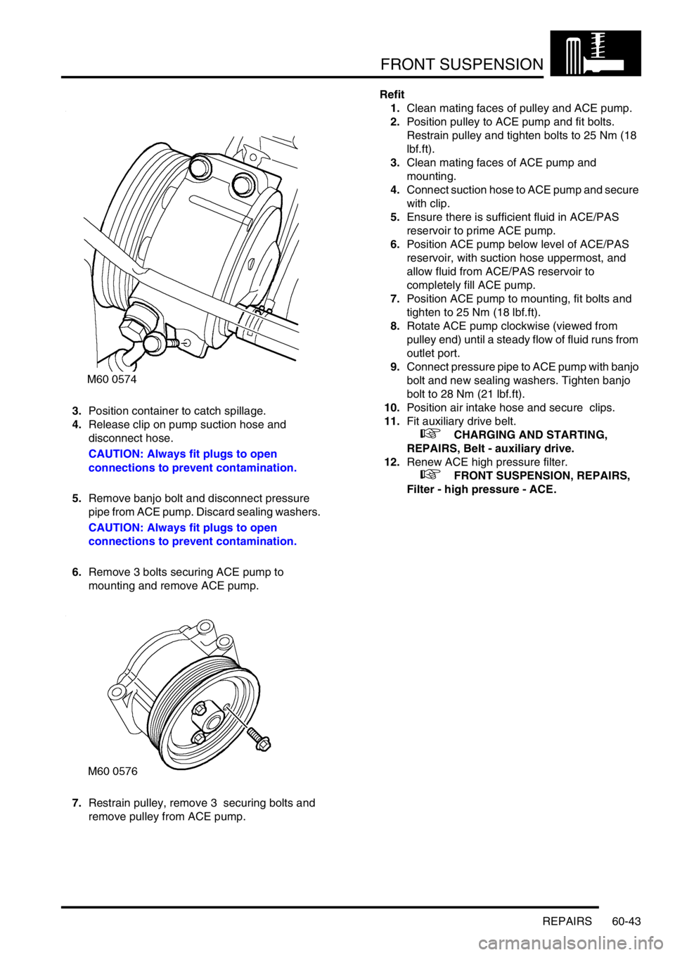
3.Position container to catch spillage.
4.Release clip on pump suction hose and
disconnect hose.
CAUTION: Always fit plugs to open
connections to prevent contamination.
5.Remove banjo bolt and disconnect pressure
pipe from ACE pump. Discard sealing washers.
CAUTION: Always fit plugs to open
connections to prevent contamination.
6.Remove 3 bolts securing ACE pump to
mounting and remove ACE pump.
7.Restrain pulley, remove 3 securing bolts and
remove pulley from ACE pump. Refit
1.Clean mating faces of pulley and ACE pump.
2.Position pulley to ACE pump and fit bolts.
Restrain pulley and tighten bolts to 25 Nm (18
lbf.ft).
3.Clean mating faces of ACE pump and
mounting.
4.Connect suction hose to ACE pump and secure
with clip.
5.Ensure there is sufficient fluid in ACE/PAS
reservoir to prime ACE pump.
6.Position ACE pump below level of ACE/PAS
reservoir, with suction hose uppermost, and
allow fluid from ACE/PAS reservoir to
completely fill ACE pump.
7.Position ACE pump to mounting, fit bolts and
tighten to 25 Nm (18 lbf.ft).
8.Rotate ACE pump clockwise (viewed from
pulley end) until a steady flow of fluid runs from
outlet port.
9.Connect pressure pipe to ACE pump with banjo
bolt and new sealing washers. Tighten banjo
bolt to 28 Nm (21 lbf.ft).
10.Position air intake hose and secure clips.
11.Fit auxiliary drive belt.
+ CHARGING AND STARTING,
REPAIRS, Belt - auxiliary drive.
12.Renew ACE high pressure filter.
+ FRONT SUSPENSION, REPAIRS,
Filter - high pressure - ACE.
Page 984 of 1672
FRONT SUSPENSION
REPAIRS 60-45
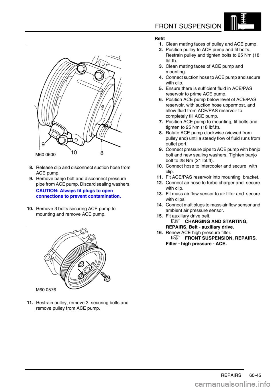
8.Release clip and disconnect suction hose from
ACE pump.
9.Remove banjo bolt and disconnect pressure
pipe from ACE pump. Discard sealing washers.
CAUTION: Always fit plugs to open
connections to prevent contamination.
10.Remove 3 bolts securing ACE pump to
mounting and remove ACE pump.
11.Restrain pulley, remove 3 securing bolts and
remove pulley from ACE pump.Refit
1.Clean mating faces of pulley and ACE pump.
2.Position pulley to ACE pump and fit bolts.
Restrain pulley and tighten bolts to 25 Nm (18
lbf.ft).
3.Clean mating faces of ACE pump and
mounting.
4.Connect suction hose to ACE pump and secure
with clip.
5.Ensure there is sufficient fluid in ACE/PAS
reservoir to prime ACE pump.
6.Position ACE pump below level of ACE/PAS
reservoir, with suction hose uppermost, and
allow fluid from ACE/PAS reservoir to
completely fill ACE pump.
7.Position ACE pump to mounting, fit bolts and
tighten to 25 Nm (18 lbf.ft).
8.Rotate ACE pump clockwise (viewed from
pulley end) until a steady flow of fluid runs from
outlet port.
9.Connect pressure pipe to ACE pump with banjo
bolt and new sealing washers. Tighten banjo
bolt to 28 Nm (21 lbf.ft).
10.Connect hose to intercooler and secure with
clip.
11.Fit ACE/PAS reservoir into mounting bracket.
12.Connect air hose to turbo charger and secure
with clip.
13.Fit mass air flow sensor to air filter and secure
with clips.
14.Connect multiplugs to mass air flow sensor and
ambient air pressure sensor.
15.Fit auxiliary drive belt.
+ CHARGING AND STARTING,
REPAIRS, Belt - auxiliary drive.
16.Renew ACE high pressure filter.
+ FRONT SUSPENSION, REPAIRS,
Filter - high pressure - ACE.
Page 1074 of 1672
BRAKES
ADJUSTMENTS 70-29
ADJUST ME NTS
Handbrake
$% 70.45.09
Check
1.Apply the handbrake lever 3 notches on the
ratchet. The handbrake should be fully
operational.
2.If the handbrake is not fully operational, the
brake shoes and/or the handbrake cable need
adjusting.
Adjust
1.Raise rear of vehicle.
WARNING: Do not work on or under a
vehicle supported only by a jack. Always
support the vehicle on safety stands.
2.Ensure handbrake lever is fully released.
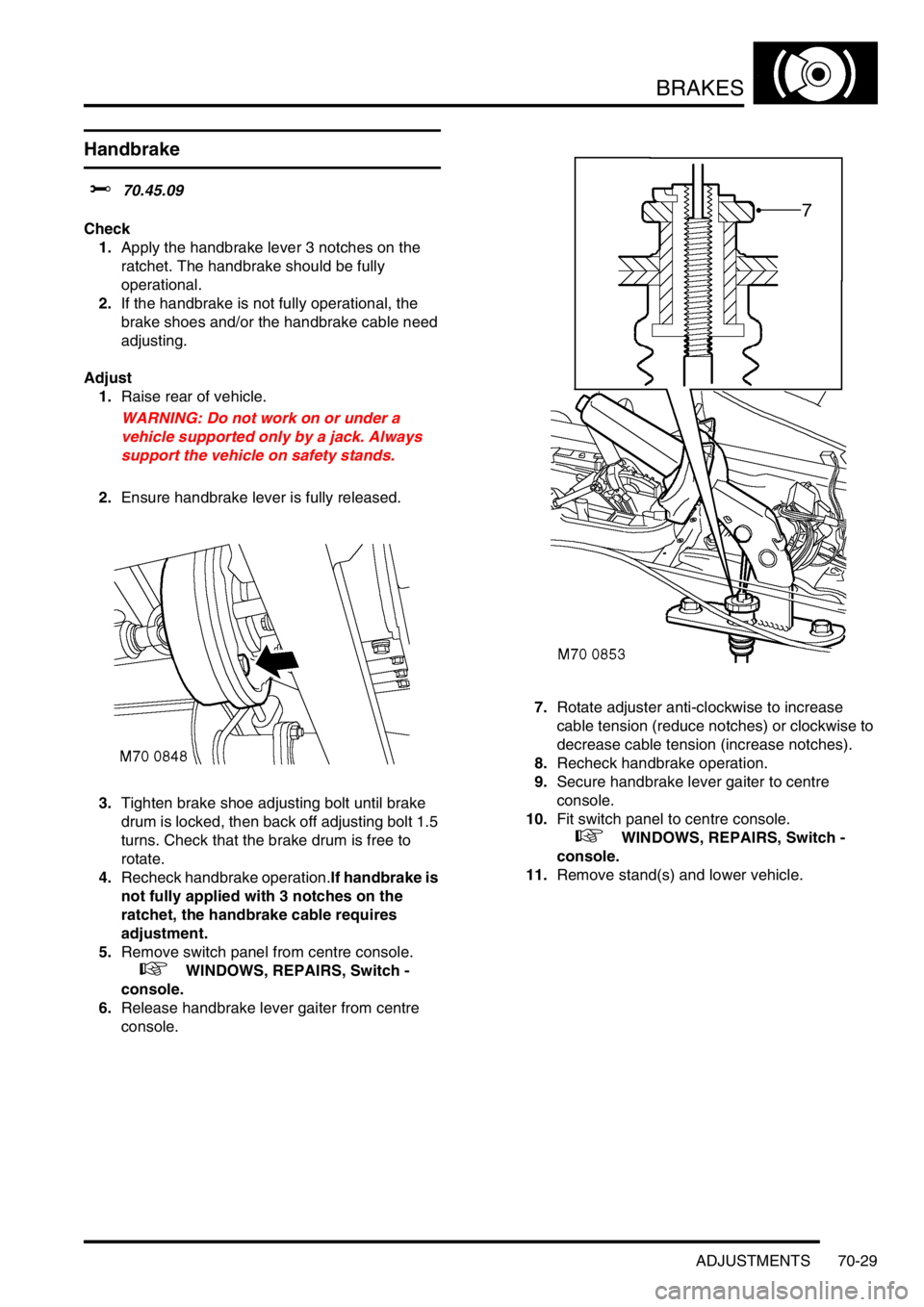
3.Tighten brake shoe adjusting bolt until brake
drum is locked, then back off adjusting bolt 1.5
turns. Check that the brake drum is free to
rotate.
4.Recheck handbrake operation.If handbrake is
not fully applied with 3 notches on the
ratchet, the handbrake cable requires
adjustment.
5.Remove switch panel from centre console.
+ WINDOWS, REPAIRS, Switch -
console.
6.Release handbrake lever gaiter from centre
console.7.Rotate adjuster anti-clockwise to increase
cable tension (reduce notches) or clockwise to
decrease cable tension (increase notches).
8.Recheck handbrake operation.
9.Secure handbrake lever gaiter to centre
console.
10.Fit switch panel to centre console.
+ WINDOWS, REPAIRS, Switch -
console.
11.Remove stand(s) and lower vehicle.