radio LAND ROVER DISCOVERY 2002 User Guide
[x] Cancel search | Manufacturer: LAND ROVER, Model Year: 2002, Model line: DISCOVERY, Model: LAND ROVER DISCOVERY 2002Pages: 1672, PDF Size: 46.1 MB
Page 1170 of 1672
INTERIOR TRIM COMPONENTS
REPAIRS 76-3-17
9.Fit drinks tray.
+ INTERIOR TRIM COMPONENTS,
REPAIRS, Drink tray assembly - centre
fascia.
10.Fit and secure radio DIN socket.
11.Fit screw cover to radio aperture.
12.Fit radio cassette player.
+ IN CAR ENTERTAINMENT,
REPAIRS, Radio cassette player.
Carpet - front
$% 76.49.02
Remove
1. Models with premium ICE: Remove power
amplifier.
+ IN CAR ENTERTAINMENT,
REPAIRS, Amplifier - power.
2. Models with premium ICE: Remove CD
autochanger.
+ IN CAR ENTERTAINMENT,
REPAIRS, CD autochanger.
3.Remove centre console.
lFor models with manual gearbox:
+ INTERIOR TRIM COMPONENTS,
REPAIRS, Console - centre - manual
models.
lFor models with automatic gearbox:
+ INTERIOR TRIM COMPONENTS,
REPAIRS, Console - centre - automatic
models.
4.Remove both lower 'A' post trim panels.
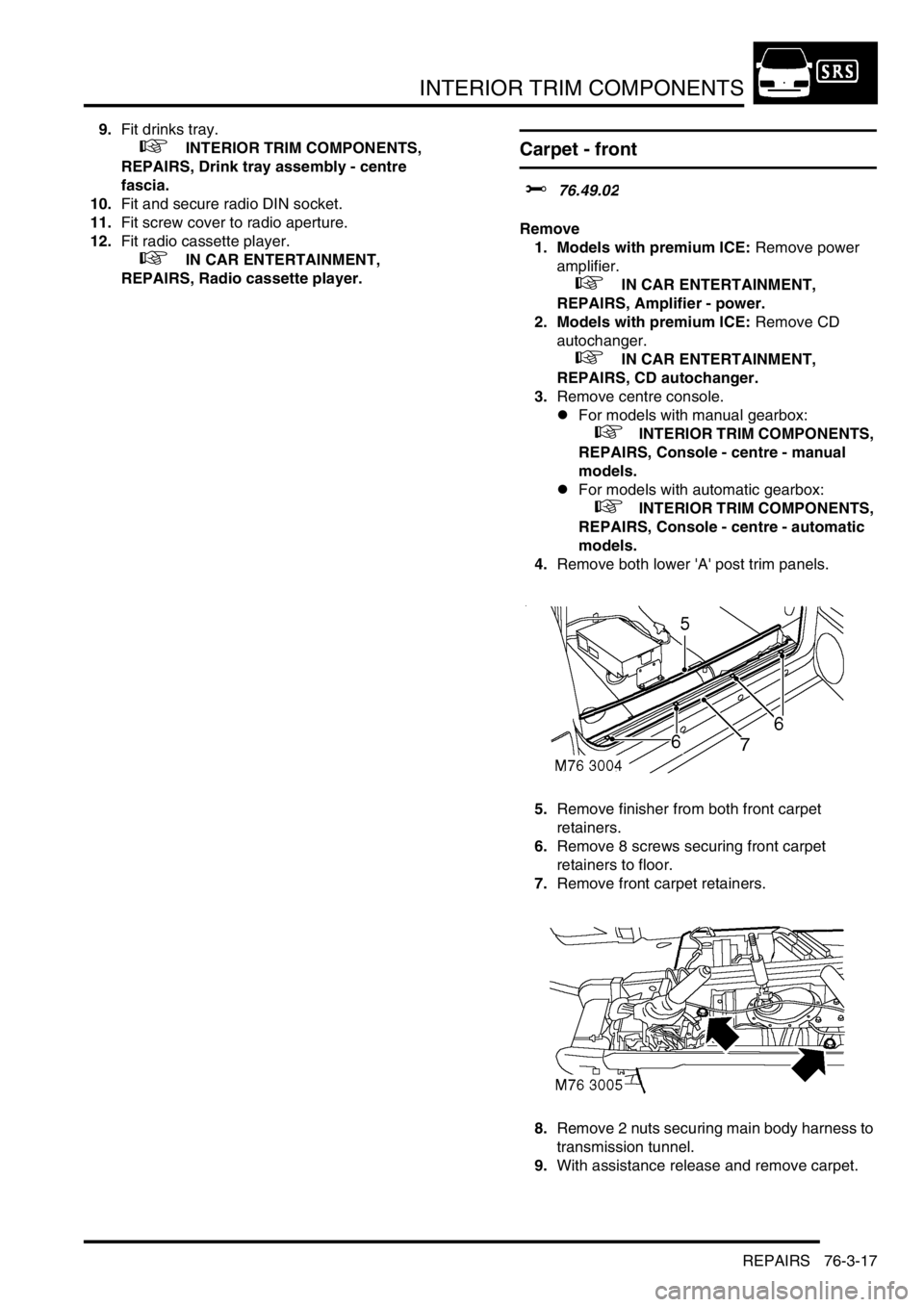
5.Remove finisher from both front carpet
retainers.
6.Remove 8 screws securing front carpet
retainers to floor.
7.Remove front carpet retainers.
8.Remove 2 nuts securing main body harness to
transmission tunnel.
9.With assistance release and remove carpet.
Page 1349 of 1672

HEATING AND VENTILATION
80-8DESCRIPTION AND OPERATION
Control panel
The controls for heating and ventilation are installed on a control panel in the centre of the fascia, below the radio.
Three rotary knobs control the LH and RH outlet temperatures and distribution. A slider switch controls blower speed.
A latching pushswitch controls the selection of fresh/recirculated air; an amber LED in the switch illuminates when
recirculated air is selected.
Graphics on the panel and the controls indicate the function and operating positions of the controls.
Outlet vent
The outlet vent promotes the free flow of heating and ventilation air through the cabin. The outlet vent is installed in
the RH rear quarter body panel and vents cabin air into the sheltered area between the rear quarter body panel and
the outer body side panel. The vent consists of a grille covered by soft rubber flaps and is effectively a non-return
valve. The flap opens and closes automatically depending on the differential between cabin and outside air pressures.
FBH system (diesel models only)
The FBH system is an auxiliary heating system that compensates for the relatively low coolant temperatures inherent
in the diesel engine. At low ambient temperatures, the FBH system heats the coolant supply to the heater assembly,
and maintains it within the temperature range required for good in-car heating performance. Operation is fully
automatic, with no intervention required by the driver.
The system consists of an air temperature sensor, a FBH fuel pump and a FBH unit. Fuel for the FBH system is taken
from the fuel tank, through a line attached to the fuel tank's fuel pump, and supplied via the FBH fuel pump to the FBH
unit. The connection on the fuel tank's fuel pump incorporates a tube which extends down into the tank. At the FBH
unit connection, the fuel line incorporates a self-sealing, quick disconnect coupling. In the FBH unit, the fuel delivered
by the FBH fuel pump is burned and the resultant heat output is used to heat the coolant. An ECU integrated into the
FBH unit controls the operation of the system at one of two heat output levels, 2.5 kW at part load and 5 kW at full load
Ambient temperature sensor
The ambient temperature sensor controls a power supply from the alternator to the FBH unit. The sensor is installed
on the RH support strut of the bonnet closing panel and contains a temperature sensitive switch that is closed at
temperatures below 5
°C (41 °F) and open at temperatures of 5 °C (41 °F) and above.
Page 1363 of 1672
HEATING AND VENTILATION
80-22REPAIRS
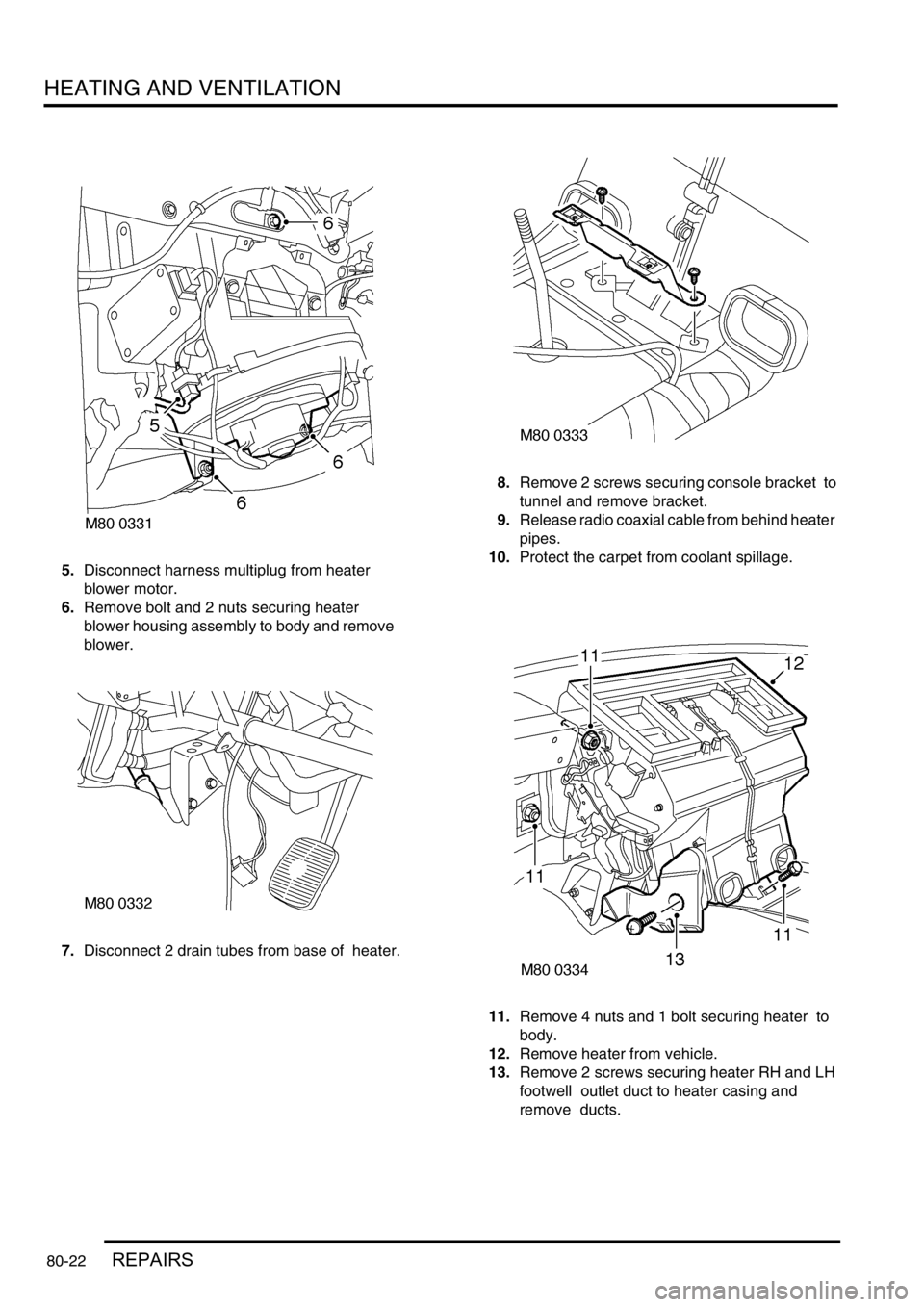
5.Disconnect harness multiplug from heater
blower motor.
6.Remove bolt and 2 nuts securing heater
blower housing assembly to body and remove
blower.
7.Disconnect 2 drain tubes from base of heater. 8.Remove 2 screws securing console bracket to
tunnel and remove bracket.
9.Release radio coaxial cable from behind heater
pipes.
10.Protect the carpet from coolant spillage.
11.Remove 4 nuts and 1 bolt securing heater to
body.
12.Remove heater from vehicle.
13.Remove 2 screws securing heater RH and LH
footwell outlet duct to heater casing and
remove ducts.
Page 1364 of 1672

HEATING AND VENTILATION
REPAIRS 80-23
14.Remove 2 screws securing matrix pipe bracket
to heater casing.
15.Remove screw securing pipe clamp to heater
casing and remove clamp.
16.Carefully remove matrix from heater.
Refit
1.Fit matrix into heater casing.
2.Fit screws securing pipe bracket to heater
casing.
3.Fit pipe clamp and secure with screw.
4.Fit heater ducts and secure with screws.
5.Position heater assembly to vehicle, ensure
heater coolant pipe grommet is correctly
located in bulkhead and secure with nuts and
bolt.
6.Fit radio coaxial cable behind heater pipes.
7.Fit console bracket and secure with screws.
8.Connect drain tubes to base of heater.
9.Fit blower unit to heater and secure to body
with nuts and bolt.
10.Connect harness multiplug to blower motor.
11.Fit facia assembly
+ INTERIOR TRIM COMPONENTS,
REPAIRS, Fascia.
12.Connect heater hoses and secure with clips.
13. Diesel models: Fit engine cover and secure
with bolts.
14.Refill cooling system
l
+ COOLING SYSTEM - Td5,
ADJUSTMENTS, Drain and refill.
l
+ COOLING SYSTEM - V8,
ADJUSTMENTS, Drain and refill.
Heater assembly - models with air
conditioning
$% 80.20.01.98
Remove
1.Drain cooling system.
l
+ COOLING SYSTEM - V8,
ADJUSTMENTS, Drain and refill.
l
+ COOLING SYSTEM - Td5,
ADJUSTMENTS, Drain and refill.
2.Evacuate air conditioning system.
+ AIR CONDITIONING, REFRIGERANT
RECOVERY, RECYCLING AND
RECHARGING, Refrigerant recovery,
recycling and recharging.
3.Release 2 clips securing heater hoses to
heater and release hoses.
4.Remove 2 bolts securing air conditioning pipes
to evaporator, release pipes and discard 'O'
rings.
CAUTION: Always fit plugs to open
connections to prevent contamination.
5.Remove fascia.
+ INTERIOR TRIM COMPONENTS,
REPAIRS, Fascia.
Page 1385 of 1672
AIR CONDITIONING
82-12DESCRIPTION AND OPERATION
Control system
The control system operates the refrigerant system and the control flaps in the heater assembly to control the
temperature and distribution of air in the vehicle interior. It also outputs signals to the fresh/recirculated air servo motor
and the blower to control the volume and source of inlet air. The control system consists of:
lAn Air Temperature Control (ATC) ECU.
lA dual pressure switch.
lAn evaporator temperature sensor.
lAn in-car temperature sensor.
lA sunlight sensor.
lA heater coolant temperature sensor.
lAn ambient temperature sensor.
ATC ECU
The ATC ECU is installed in the centre of the fascia, below the radio. An integral control panel on the ATC ECU
contains switches for system control inputs and a LCD to provide system status information.
Inputs from sensors and the control panel switches are processed by the ATC ECU, which then outputs the
appropriate control signals.
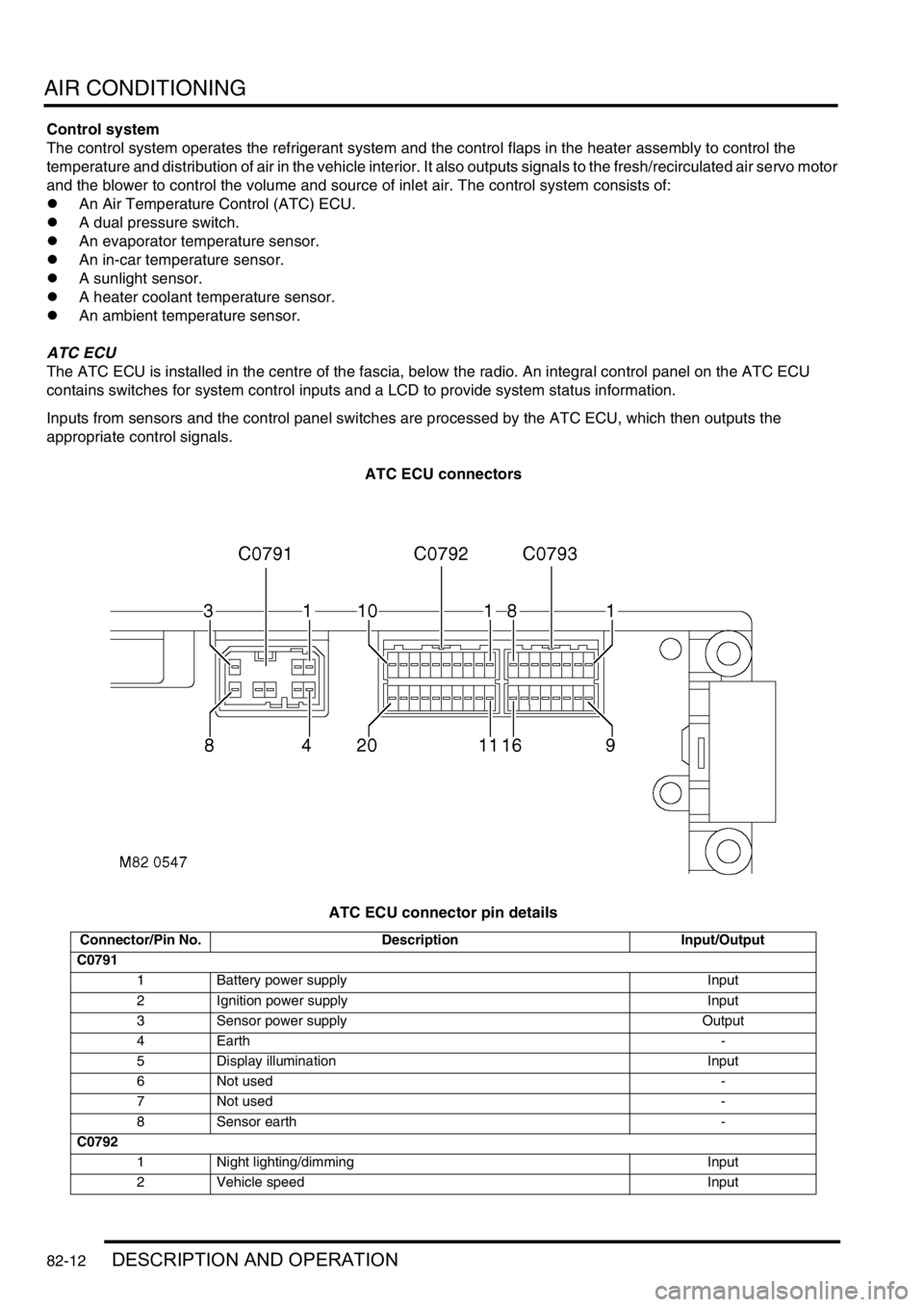
ATC ECU connectors
ATC ECU connector pin details
Connector/Pin No. Description Input/Output
C0791
1 Battery power supply Input
2 Ignition power supply Input
3 Sensor power supply Output
4Earth-
5 Display illumination Input
6 Not used-
7 Not used-
8 Sensor earth -
C0792
1 Night lighting/dimming Input
2 Vehicle speed Input
Page 1410 of 1672
AIR CONDITIONING
REPAIRS 82-37
12.Remove receiver drier from mounting bracket.
13.Remove dual pressure switch from receiver
drier
Refit
1.Fit dual pressure switch to receiver drier and
tighten to 10 Nm (7 lbf.ft).
2.Fit receiver drier to mounting bracket and
tighten clamping bolt.
3.Fit receiver drier assembly to condenser.
4.Fit bolts securing receiver drier mounting
bracket to condenser and tighten to 5 Nm (3.7
lbf.ft).
5.Remove caps from air conditioning pipes and
receiver drier.
6.Remove old 'O' rings from pipes.
7.Fit new 'O' rings to pipes and lubricate with
refrigerant oil.
8.Connect air conditioning pipes to receiver
drier.
9.Fit bolts securing air conditioning pipes to
receiver drier and tighten to 5 Nm (3.7 lbf.ft).
10.Connect multiplug to dual pressure switch.
11.Fit front grille.
+ EXTERIOR FITTINGS, REPAIRS,
Grille - front - up to 03MY.
12.Recharge air conditioning system.
+ AIR CONDITIONING, REFRIGERANT
RECOVERY, RECYCLING AND
RECHARGING, Refrigerant recovery,
recycling and recharging.
ECU - air temperature control
$% 82.20.90
Remove
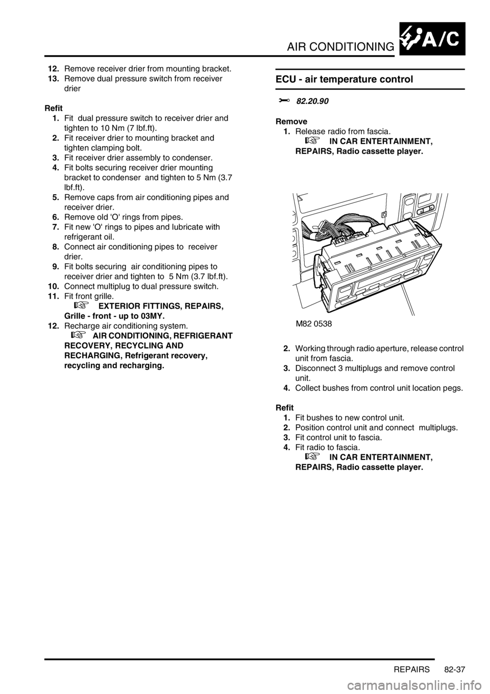
1.Release radio from fascia.
+ IN CAR ENTERTAINMENT,
REPAIRS, Radio cassette player.
2.Working through radio aperture, release control
unit from fascia.
3.Disconnect 3 multiplugs and remove control
unit.
4.Collect bushes from control unit location pegs.
Refit
1.Fit bushes to new control unit.
2.Position control unit and connect multiplugs.
3.Fit control unit to fascia.
4.Fit radio to fascia.
+ IN CAR ENTERTAINMENT,
REPAIRS, Radio cassette player.
Page 1432 of 1672
WIPERS AND WASHERS
DESCRIPTION AND OPERATION 84-11
The dc motor contains two permanent magnets, three brushes and a park switch. The smaller third brush is utilised
for high-speed operation. Attached to the brush pack are 3 capacitors, which minimise radio interference during wiper
operation. A thermal trip switch attached to the brush plate prevents thermal overload of the motor.
The motor incorporates a worm drive gear unit to transfer the rotary motion into a linear motion of the wiper linkage
assembly.
The front wiper motor receives battery voltage from fuse 19 of the passenger compartment fuse box. For low-speed
operation, including intermittent variable delay operation, the battery voltage to move the wiper motor from the park
position passes through the front wiper relay. When the park switch moves to the closed when operating position,
fuse 19 of the passenger compartment fuse box provides battery voltage directly to the wiper motor.
For high-speed operation, including flick wipe, fuse 19 in the passenger compartment fuse box provides the battery
voltage to move the wiper motor from the park position through the front wash/ wipe switch to the front wiper motor.
To achieve high-speed wiper operation, power is supplied to a third brush that provides a closer distance between the
motor poles. Because the poles of the motor are closer together, the motor operates faster.
Rear wiper
The rear wiper is driven directly from an electric motor located inside the tail door. The motor is mounted inside the
tail door with two bolts, lock washers and washers. The motor mounting brackets have rubber inserts to prevent motor
operating noise being transferred to the door structure. The motor spindle is fitted with a seal and protrudes through
a hole in the tail door outer skin panel. The motor spindle is secured to the tail door with a washer and nut.
The motor output spindle has a taper splined shaft which allows for the attachment of the wiper arm which is secured
with a nut. The wiper arm attachment to the splined shaft has a pivot to which the remainder of the arm is attached.
The two parts of the arm are connected by a spring which controls the pressure of the blade on the window to a
predetermined amount.
The wiper blade is attached to the wiper arms with a clip which allows the blade to pivot. The wiper blade comprises
of a number of levers and yokes to which the rubber wiper is attached. The levers and yokes ensure that the pressure
applied by the arm spring is evenly distributed along the full length of the blade. The rubber wiper is held in the yokes
by a pair of stainless steel strips which also contribute to the even distribution of spring pressure along the blade.
Rear wiper switch
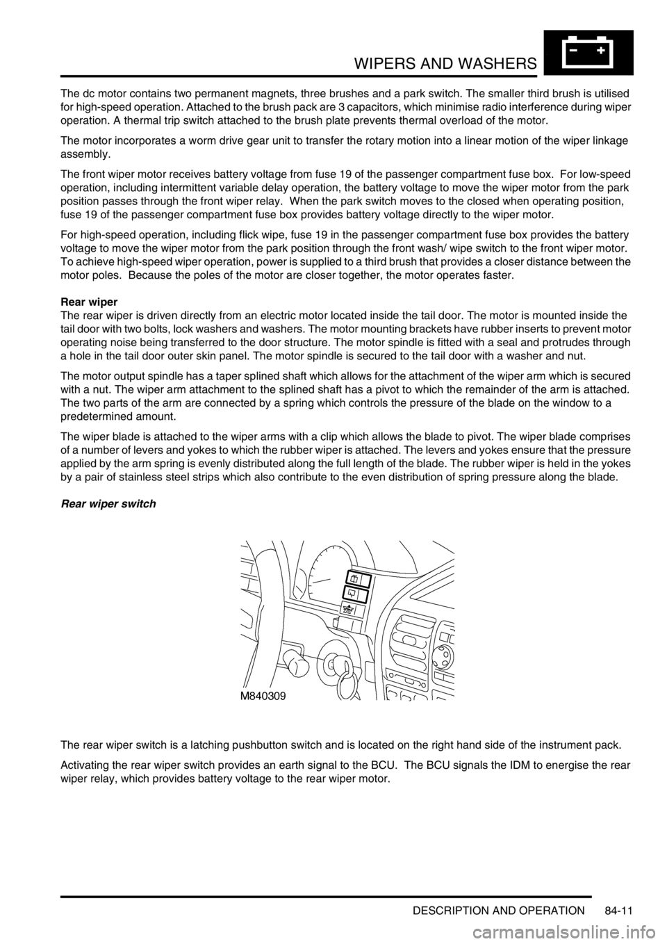
The rear wiper switch is a latching pushbutton switch and is located on the right hand side of the instrument pack.
Activating the rear wiper switch provides an earth signal to the BCU. The BCU signals the IDM to energise the rear
wiper relay, which provides battery voltage to the rear wiper motor.
Page 1433 of 1672
WIPERS AND WASHERS
84-12 DESCRIPTION AND OPERATION
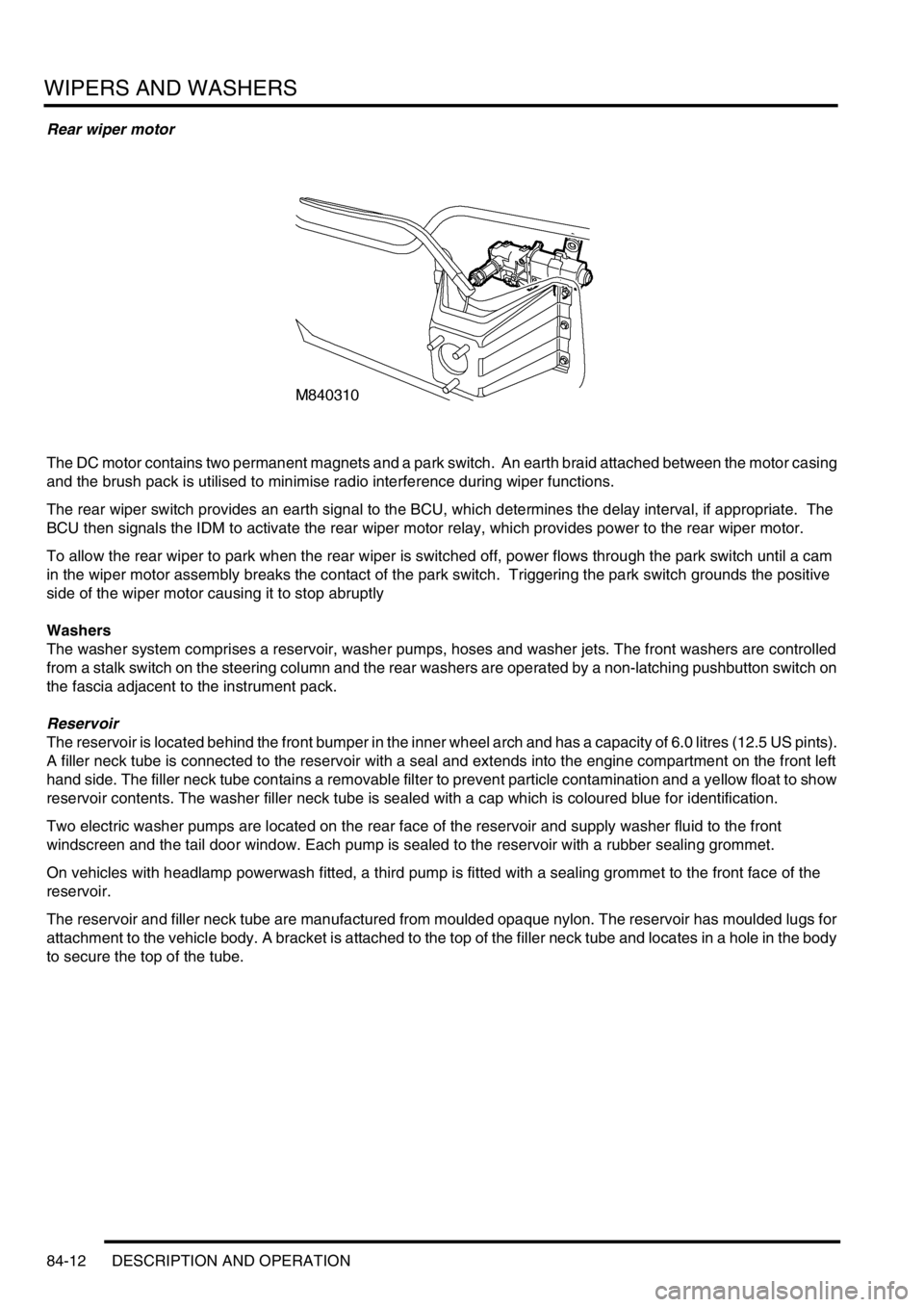
Rear wiper motor
The DC motor contains two permanent magnets and a park switch. An earth braid attached between the motor casing
and the brush pack is utilised to minimise radio interference during wiper functions.
The rear wiper switch provides an earth signal to the BCU, which determines the delay interval, if appropriate. The
BCU then signals the IDM to activate the rear wiper motor relay, which provides power to the rear wiper motor.
To allow the rear wiper to park when the rear wiper is switched off, power flows through the park switch until a cam
in the wiper motor assembly breaks the contact of the park switch. Triggering the park switch grounds the positive
side of the wiper motor causing it to stop abruptly
Washers
The washer system comprises a reservoir, washer pumps, hoses and washer jets. The front washers are controlled
from a stalk switch on the steering column and the rear washers are operated by a non-latching pushbutton switch on
the fascia adjacent to the instrument pack.
Reservoir
The reservoir is located behind the front bumper in the inner wheel arch and has a capacity of 6.0 litres (12.5 US pints).
A filler neck tube is connected to the reservoir with a seal and extends into the engine compartment on the front left
hand side. The filler neck tube contains a removable filter to prevent particle contamination and a yellow float to show
reservoir contents. The washer filler neck tube is sealed with a cap which is coloured blue for identification.
Two electric washer pumps are located on the rear face of the reservoir and supply washer fluid to the front
windscreen and the tail door window. Each pump is sealed to the reservoir with a rubber sealing grommet.
On vehicles with headlamp powerwash fitted, a third pump is fitted with a sealing grommet to the front face of the
reservoir.
The reservoir and filler neck tube are manufactured from moulded opaque nylon. The reservoir has moulded lugs for
attachment to the vehicle body. A bracket is attached to the top of the filler neck tube and locates in a hole in the body
to secure the top of the tube.
Page 1514 of 1672

ALARM SYSTEM AND HORN
DESCRIPTION AND OPERATION 86-4-5
Description
General
The anti-theft system deters the theft of the vehicle with both active and passive systems. The active systems monitor
the vehicle perimeter and, in some markets the vehicle interior, for intrusion. If the system detects intrusion, an alarm
sounds. The passive systems include a vehicle immobiliser as well as protection against intrusion through super
locking the doors. The vehicle is immobilised whenever the ignition key is removed from the ignition switch. Super
locking prevents the interior door handles from opening the doors. In addition, there are many features and functions
that enhance system operation.
It is possible to perform the various functions associated with the anti-theft system remotely. To accomplish this, the
handset generates a radio frequency when the lock button or unlock button is depressed. This signal is transmitted
to the Body Control Unit (BCU) via a receiver located in front of rear sunroof beneath the headlining. Precise alignment
of the handset to the receiver is not necessary. The approximate operating range between the handset and the
receiver is 10 metres (33 feet).
It is important to understand the configuration of the system on each particular vehicle. There are many
different combinations of features with dedicated operating modes. System configuration for each vehicle
can be determined using TestBook.
The anti-theft system is controlled centrally by the BCU, which is located below and behind the passenger glovebox.
A serial communication link communicates between the Intelligent Driver Module (IDM) located within the fusebox,
the BCU and the LED located in the instrument panel.
The state of the alarm is stored in the BCU. If the battery is disconnected while the alarm is armed, the alarm will be
triggered when the battery is reconnected.
NOTE: Disconnecting the battery while the alarm is armed triggers the alarm. Always disarm the alarm system before
disconnecting the battery.
The BCU also receives inputs from the following components:
lIgnition key in sensor.
lIgnition switch.
lFuel cut off switch.
lFuel flap release switch.
The BCU also interacts with the following components:
lStarter relay.
lVehicle horns.
lDirection indicators.
lFuel flap release actuator.
lCourtesy lamps.
Page 1520 of 1672

ALARM SYSTEM AND HORN
DESCRIPTION AND OPERATION 86-4-11
Central door locking switches
A momentary action switch mounted on the fascia allows for central door locking/unlocking from within the vehicle.
The switch is mounted adjacent to the clock.
Input/Output
The input from the central door locking/unlocking switch to the BCU is either zero volts or an open circuit. Zero volts
indicates the switch is closed. An open circuit indicates that the switch is open. When the BCU sees an open circuit,
it pulls the input high internally.
The central door locking/unlocking switch has a dedicated signal input to the BCU. This allows the BCU to identify
the lock/ unlock request.
TestBook provides the ability to monitor the real time state of the central door locking/ unlocking switch.
Handset and receiver
The handset is incorporated in the key. It uses coded radio frequency signals to lock, unlock and super lock the vehicle
remotely with a range of up to 10 metres (33 ft). The handset also mobilises the vehicle by transmitting a
remobilisation signal when the handset is within range of the passive remobilisation exciter coil.
The receiver is located in front of the rear sunroof beneath the headlining. Signals transmitted by the handset are
distributed to the BCU via the receiver.
Input/Output
The BCU supplies the receiver with a 12 volts power supply. On receiving a valid signal from the handset, the receiver
transmits a 1000 baud signal to the BCU to allow locking/unlocking of the vehicle.
TestBook provides the ability to monitor the real time state of the remote receiver.