radio LAND ROVER DISCOVERY 2002 Workshop Manual
[x] Cancel search | Manufacturer: LAND ROVER, Model Year: 2002, Model line: DISCOVERY, Model: LAND ROVER DISCOVERY 2002Pages: 1672, PDF Size: 46.1 MB
Page 27 of 1672

CONTENTS
24 CONTENTS
Electric windows block diagram ...................................................................................................... 86-5-1
Electric windows component layout ................................................................................................ 86-5-2
Description ...................................................................................................................................... 86-5-4
Operation ....................................................................................................................................... 86-5-11
REPAIRS
Switch - rear door ......................................................................................................................... 86-5-13
Switch - console ............................................................................................................................ 86-5-13
Switch - heated rear screen ............................................................................................................ 86-5-14
IN CAR ENTERTAINMENT....................................................................... 86-6-1
DESCRIPTION AND OPERATION
ICE System Component layout....................................................................................................... 86-6-1
Base and mid line ICE system control diagram .............................................................................. 86-6-2
High line ICE system control diagram............................................................................................. 86-6-3
Description ...................................................................................................................................... 86-6-4
REPAIRS
Radio cassette player ..................................................................................................................... 86-6-13
Speaker - low/full range - front door ............................................................................................. 86-6-14
Speaker - low range - rear door ..................................................................................................... 86-6-14
Switches - remote control - ICE .................................................................................................... 86-6-15
Amplifier - aerial .............................................................................................................................. 86-6-15
Speaker - mid range - front door ................................................................................................... 86-6-16
Speaker - high range - rear door .................................................................................................. 86-6-16
Amplifier - power ........................................................................................................................... 86-6-17
Speaker - tail door ........................................................................................................................ 86-6-18
CD autochanger ............................................................................................................................ 86-6-18
HARNESSES ............................................................................................ 86-7-1
REPAIRS
Harness - injectors - diesel ............................................................................................................ 86-7-1
Harness - body ............................................................................................................................. 86-7-1
Harness - engine - V8 ..................................................................................................................... 86-7-8
Harness - engine - diesel ................................................................................................................ 86-7-13
Harness - main ............................................................................................................................. 86-7-16
DRIVING AIDS .......................................................................................... 86-8-1
DESCRIPTION AND OPERATION
Park Distance Control – Component Location................................................................................ 86-8-1
Park Distance Control – Control Diagram....................................................................................... 86-8-2
Description ...................................................................................................................................... 86-8-4
Operation ........................................................................................................................................ 86-8-10
REPAIRS
Control unit (ECU) - parking aid...................................................................................................... 86-8-13
Sounder - parking aid rear ............................................................................................................. 86-8-14
Sensor - parking aid - rear - inner ................................................................................................... 86-8-15
Sensor - parking aid - rear - outer .................................................................................................. 86-8-16
Page 33 of 1672

INTRODUCTION
01-4
HRW Heated Rear Window
HSLA High Strength Low Alloy
ht/HT High tension
IACV Idle Air Control Valve
IAT Intake Air Temperature
ICE In-Car Entertainment
i.dia. Internal diameter
IDM Intelligent Driver Module
IF Intermediate Frequency
in
3Cubic inch
ILT Inlet Throttle
IPW Injector Pulse Width
ISO International Organisation for
Standardisation
ITS Inflatable Tubular Structure
k Thousand
kg Kilogramme
kg/h Kilogrammes per hour
km Kilometre
km/h Kilometres per hour
kPa KiloPascal
KS Knock Sensor
lb(s) Pounds
lbf Pounds force
lbf.in Pounds force inches
lbf/in
2Pounds per square inch
lbf.ft Pounds force feet
λLambda
lc Low compression
LCD Liquid Crystal Display
LED Light Emitting Diode
LEV Low Emission Vehicle
LH Left-Hand
LHD Left-Hand Drive
LSM Light Switch Module
LVS Liquid Vapour Separator
mMetre
µMicro
MAF Mass Air Flow
MAP Manifold Absolute Pressure
MET Mechanical, Electrical and Trim
MFU Multi-Function Unit
MFL Multi-Function Logic
max. Maximum
MEMS Modular Engine Management
System
MIG Metal/Inert Gas
MIL Malfunction Indicator Lamp
MPa MegaPascal
MOSFET Metal Oxide Semiconductor Field
Effect Transistor
min. Minimum
- Minus (tolerance)
' Minute (angle)
mm Millimetre
mph Miles per hour MPi Multi-Point injection
MV Motorised Valve
MY Model Year
NAS North American Specification
(-) Negative (electrical)
Nm Newton metre
No. Number
NO
2Nitrogen Dioxide
NO
xOxides of Nitrogen
NTC Negative Temperature
Coefficient
NRV Non Return Valve
OBD On Board Diagnostics
OBM On Board Monitoring
o.dia. Outside diameter
OAT Organic Acid Technology
ORM Off-road Mode
ΩOhm
PAS Power Assisted Steering
PCB Printed Circuit Board
PCV Positive Crankcase Ventilation
PDC Parking Distance Control
PDOP Position Dilation Of Precision
PI Programme Information
PPS Pulse Per Second
PS Programme Service
psi Pounds per square inch
pts. Pints
% Percentage
+ Plus (tolerance) or Positive
(electrical)
±Plus or minus (tolerance)
PTC Positive Temperature Coefficient
PTFE Polytetrafluorethylene
PVC Polyvinyl chloride
PWM Pulse Width Modulation
RDS Radio Data Service
rRadius
:Ratio
ref Reference
REG Regionalisation
RES Rover Engineering Standards
rev/min Revolutions per minute
RF Radio Frequency
RGB Red / Green / Blue
RH Right-Hand
RHD Right-Hand Drive
ROM Read Only Memory
RON Research Octane Number
ROV Roll Over Valve
ROW Rest Of World
SAE Society of Automotive Engineers
SAI Secondary Air Injection
" Second (angle)
SLABS Self Levelling and Anti-Lock
Brake System
SLS Self Levelling Suspension
SOHC Single Overhead Camshaft
Page 52 of 1672
GENERAL INFORMATION
03-17
Electrical Precautions
General
The following guidelines are intended to ensure the
safety of the operator while preventing damage to the
electrical and electronic components fitted to the
vehicle. Where necessary, specific precautions are
detailed in the individual procedures of this manual.
Equipment
Prior to commencing any test procedure on the
vehicle ensure that the relevant test equipment is
working correctly and any harness or connectors are
in good condition. It is particularly important to check
the condition of the lead and plugs of mains operated
equipment.
Polarity
Never reverse connect the vehicle battery and
always ensure the correct polarity when connecting
test equipment.
High voltage circuits
Whenever disconnecting live ht circuits always use
insulated pliers and never allow the open end of the
ht lead to contact other components, particularly
ECU's. Exercise caution when measuring the voltage
on the coil terminals while the engine is running, high
voltage spikes can occur on these terminals.
Connectors and harnesses
The engine compartment of a vehicle is a particularly
hostile environment for electrical components and
connectors:
lAlways ensure electrically related items are dry
and oil free before disconnecting and
connecting test equipment.
lEnsure disconnected multiplugs and sensors
are protected from being contaminated with oil,
coolant or other solutions. Contamination could
impair performance or result in catastrophic
failure.
lNever force connectors apart using tools to
prise apart or by pulling on the wiring harness.
lAlways ensure locking tabs are disengaged
before disconnection, and match orientation to
enable correct reconnection.
lEnsure that any protection (covers, insulation
etc.) is replaced if disturbed.Having confirmed a component to be faulty:
lSwitch off the ignition and disconnect the
battery.
lRemove the component and support the
disconnected harness.
lWhen replacing the component keep oily hands
away from electrical connection areas and push
connectors home until any locking tabs fully
engage.
Battery disconnection
Before disconnecting the battery, disable the alarm
system and switch off all electrical equipment. If the
radio is to be serviced, ensure the security code has
been deactivated.
CAUTION: To prevent damage to electrical
components, always disconnect the battery
when working on the vehicle's electrical system.
The ground lead must be disconnected first and
reconnected last.
CAUTION: Always ensure that battery leads are
routed correctly and are not close to any
potential chafing points.
Battery charging
Only recharge the battery with it removed from the
vehicle. Always ensure any battery charging area is
well ventilated and that every precaution is taken to
avoid naked flames and sparks.
Ignition system safety precautions
The vehicle's ignition system produces high voltage
and the following precautions should be observed
before carrying out any work on the system.
WARNING: Before commencing work on an
ignition system, ensure all high tension
terminals, adapters and diagnostic equipment
are adequately insulated and shielded to prevent
accidental personal contacts and minimise the
risk of shock. Wearers of surgically implanted
pacemaker devices should not be in close
proximity of ignition circuits or diagnostic
equipment.
Disciplines
Switch off the ignition prior to making any connection
or disconnection in the system to prevent electrical
surges caused by disconnecting 'live' connections
damaging electronic components.
Ensure hands and work surfaces are clean and free
of grease, swarf, etc. Grease collects dirt which can
cause electrical tracking (short-circuits) or high-
resistance contacts.
When handling printed circuit boards, treat with care
and hold by the edges only; note that some electronic
components are susceptible to body static.
Page 56 of 1672
GENERAL INFORMATION
03-21
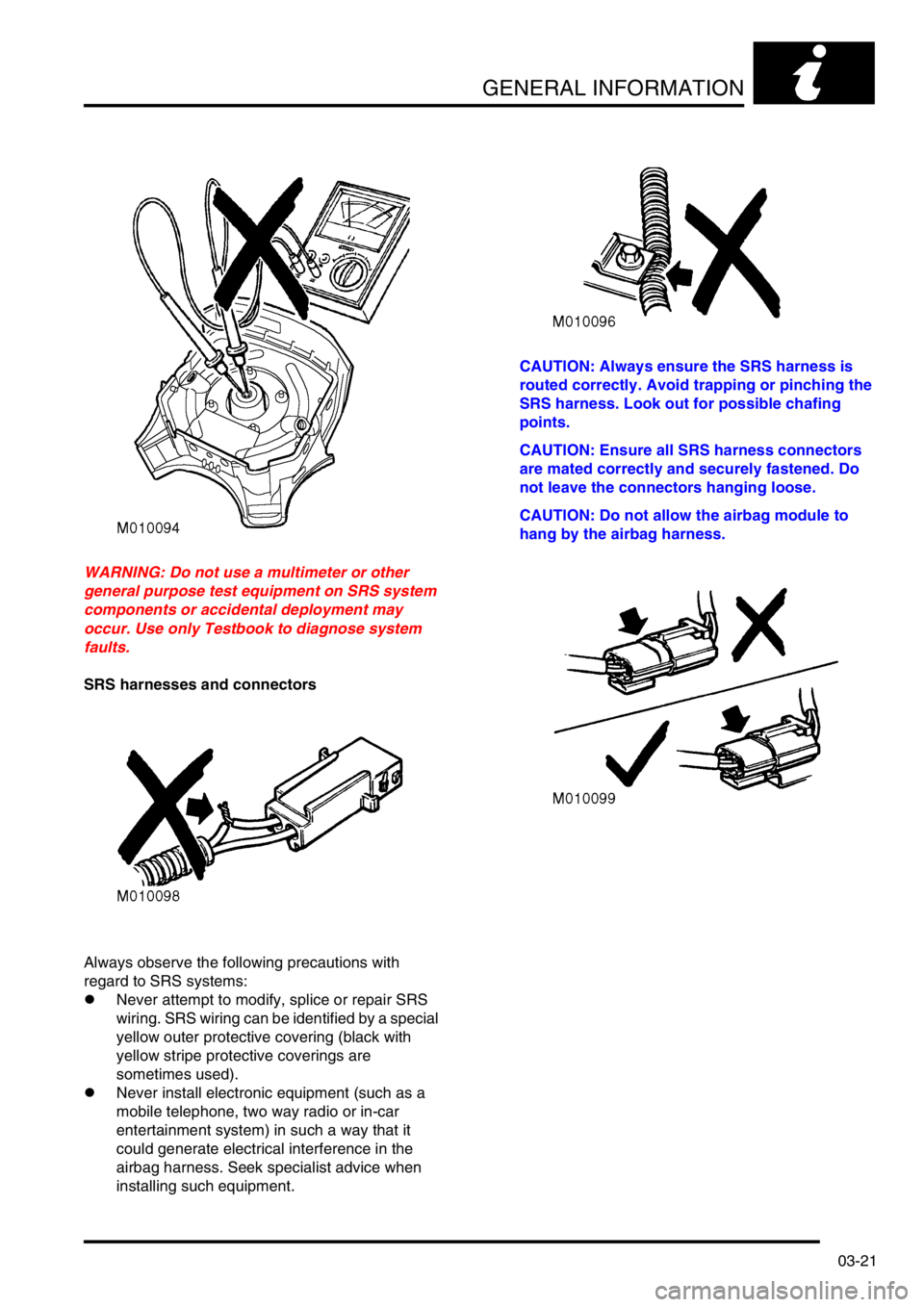
WARNING: Do not use a multimeter or other
general purpose test equipment on SRS system
components or accidental deployment may
occur. Use only Testbook to diagnose system
faults.
SRS harnesses and connectors
Always observe the following precautions with
regard to SRS systems:
lNever attempt to modify, splice or repair SRS
wiring. SRS wiring can be identified by a special
yellow outer protective covering (black with
yellow stripe protective coverings are
sometimes used).
lNever install electronic equipment (such as a
mobile telephone, two way radio or in-car
entertainment system) in such a way that it
could generate electrical interference in the
airbag harness. Seek specialist advice when
installing such equipment.CAUTION: Always ensure the SRS harness is
routed correctly. Avoid trapping or pinching the
SRS harness. Look out for possible chafing
points.
CAUTION: Ensure all SRS harness connectors
are mated correctly and securely fastened. Do
not leave the connectors hanging loose.
CAUTION: Do not allow the airbag module to
hang by the airbag harness.
Page 890 of 1672

STEERING
DESCRIPTION AND OPERATION 57-3
1Air bag module
2Steering wheel and nut
3Horn switch 2 off
4Radio remote control switch (if fitted)
5Column switches
6Lower nacelle
7Column tilt adjustment lever
8Steering column lock
9Ignition switch and harness
10Upper column assembly
11Lower column
12Universal joint 13Bolt
14Bolt
15Intermediate shaft assembly
16Decouple joint
17Rubber coupling and heat shield
18Bolt
19Universal joint
20Shear bolt 2 off
21Rotary coupler
22Upper nacelle
23Cruise control switch (if fitted)
Page 893 of 1672

STEERING
57-6 DESCRIPTION AND OPERATION
Tilt adjustment
The column tilt adjuster lever mechanism is located on the LH side of the steering column and allows the upper column
tube, nacelle and steering wheel assemblies to be tilted up or down a maximum of 7.5
° or 47 mm (NAS vehicles have
a smaller range of movement than the ROW vehicles).
The pawl of the mechanism is attached to the lower column and is allowed to pivot, a toothed quadrant is fixed to the
upper column tube.
When the lever on the LH side of the steering column is raised the mechanism releases the pawl from the toothed
quadrant, this allows the column to be moved. When the lever is released two return springs pull the pawl into
engagement with the toothed quadrant.
Steering column lock (All except NAS)
The steering column lock houses the ignition switch, ignition illumination light ring, key lock barrel and the alarm
passive coil. The steering lock is attached to the upper column with two shear bolts. The bolts are tightened to a
torque which shears off the heads of the bolts preventing easy removal of the steering lock.
The steering lock operates by a bolt, which emerges when the ignition key is turned to position 'O' and the ignition key
removed. The bolt engages in a lock collar located on the upper shaft in the upper column tube. The lock collar is
attached to the upper shaft by a 'wave form' interference ring. If a high torque is applied via the steering wheel with
the lock engaged, the lock collar will slip on the upper shaft. This prevents damage to the steering lock, yet still
prevents the vehicle from being driven.
Steering column lock (NAS only)
The steering column lock houses the ignition switch, ignition illumination light ring, key lock barrel and the alarm
passive coil. The steering lock is attached to the upper column with two shear bolts. The bolts are tightened to a
torque which shears off the heads of the bolts preventing easy removal of the steering lock.
The steering column lock operates by a bolt, which emerges when the ignition key is turned to position 'O' and the
ignition key removed. The bolt engages in a groove machined into the upper shaft in the column tube.
Steering wheel
The steering wheel comprises a cast centre and wire frame onto which the soft polyurethane foam is moulded. The
steering wheel is located on the upper column shaft by a spline and is secured with a nut. A remote radio control switch
(if fitted) is located on the LH side of the steering wheel, a cruise control switch may be located on the RH side. Horn
switches are located on each side of the centre of the steering wheel and protrude through the airbag module cover.
Both switches are connected by wires to the rotary coupler connector.
Intermediate shaft
One end of the intermediate shaft is attached to the steering column lower shaft by a splined universal joint and a bolt,
the universal joint is part of a rubber coupling assembly. The rubber coupling assembly is covered by a heat shield
and connects to the lower section of the intermediate shaft via a decouple joint. The rubber coupling reduces the
shocks felt by the driver through the steering wheel. A second universal joint on the other end of the intermediate shaft
is held in by a bolt. The universal joint is splined and engages with the splined rotor (input) shaft of the steering box.
The decouple joint consists of a metal plate that has open ended slots, the plate is bolted through the slots into the
other half of the decouple joint. The top half of the decouple joint has a slot that accepts the lower section of the
intermediate shaft. The slotted metal plate clamps the lower section of the intermediate shaft to the top section. An
indicator clip is installed between the slotted metal plate and the top half of the decouple joint.
If the intermediate shaft is compressed in an accident, the slotted metal plate in the decouple joint will disengage if
sufficient force is applied to the front end of the shaft. If the forces involved do not disengage the shaft, the red
indicator clip located in the decouple joint will break off if the shaft moves. The intermediate shaft cannot be repaired
and must be replaced as an assembly if accident damage occurs.
Page 939 of 1672
STEERING
57-52 REPAIRS
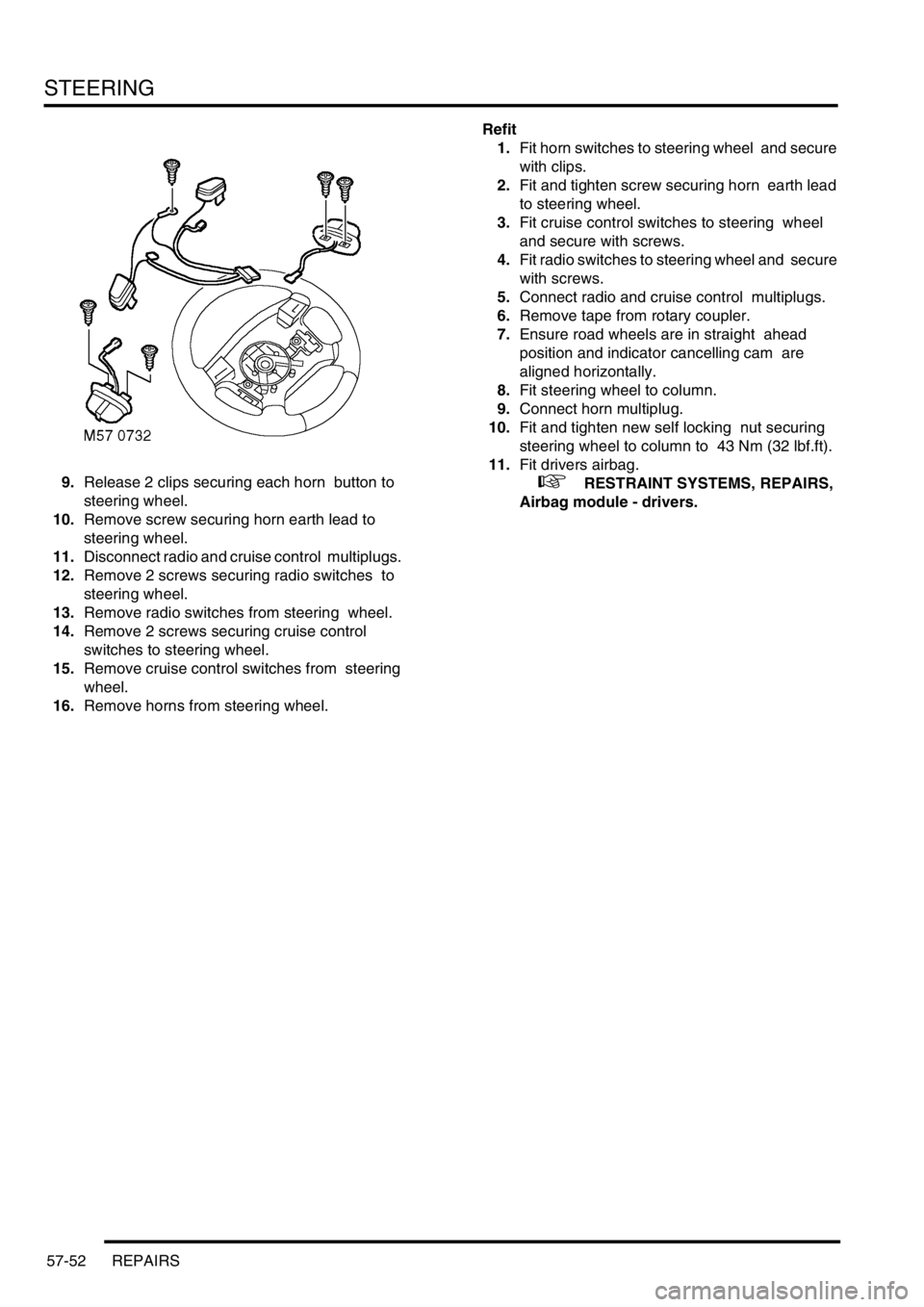
9.Release 2 clips securing each horn button to
steering wheel.
10.Remove screw securing horn earth lead to
steering wheel.
11.Disconnect radio and cruise control multiplugs.
12.Remove 2 screws securing radio switches to
steering wheel.
13.Remove radio switches from steering wheel.
14.Remove 2 screws securing cruise control
switches to steering wheel.
15.Remove cruise control switches from steering
wheel.
16.Remove horns from steering wheel. Refit
1.Fit horn switches to steering wheel and secure
with clips.
2.Fit and tighten screw securing horn earth lead
to steering wheel.
3.Fit cruise control switches to steering wheel
and secure with screws.
4.Fit radio switches to steering wheel and secure
with screws.
5.Connect radio and cruise control multiplugs.
6.Remove tape from rotary coupler.
7.Ensure road wheels are in straight ahead
position and indicator cancelling cam are
aligned horizontally.
8.Fit steering wheel to column.
9.Connect horn multiplug.
10.Fit and tighten new self locking nut securing
steering wheel to column to 43 Nm (32 lbf.ft).
11.Fit drivers airbag.
+ RESTRAINT SYSTEMS, REPAIRS,
Airbag module - drivers.
Page 1162 of 1672
INTERIOR TRIM COMPONENTS
REPAIRS 76-3-9
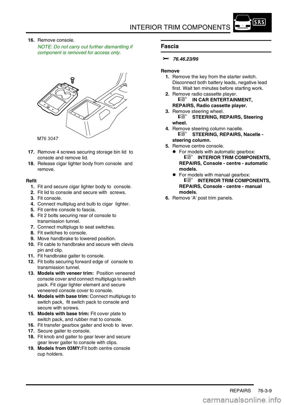
16.Remove console.
NOTE: Do not carry out further dismantling if
component is removed for access only.
17.Remove 4 screws securing storage bin lid to
console and remove lid.
18.Release cigar lighter body from console and
remove.
Refit
1.Fit and secure cigar lighter body to console.
2.Fit lid to console and secure with screws.
3.Fit console.
4.Connect multiplug and bulb to cigar lighter.
5.Fit centre console to fascia.
6.Fit 2 bolts securing rear of console to
transmission tunnel.
7.Connect multiplugs to seat switches.
8.Fit switches to console.
9.Move handbrake to lowered position.
10.Fit cable to handbrake and secure with clevis
pin and clip.
11.Fit handbrake gaiter to console.
12.Fit bolts securing forward edge of console to
transmission tunnel.
13. Models with veneer trim: Position veneered
console cover and connect multiplugs to switch
pack. Fit cigar lighter element and secure
veneered console cover to console.
14. Models with base trim: Connect multiplugs to
switch pack, fit switch pack to console and
secure with screws.
15. Models with base trim: Fit cover plate to
switch pack, and rubber mat to console.
16.Fit transfer gearbox gaiter and knob to lever.
17.Secure gaiter to console.
18.Fit knob and gaiter to gear lever and secure
gear lever gaiter to console with clips.
19. Models from 03MY:Fit both centre console
cup holders.
Fascia
$% 76.46.23/99
Remove
1.Remove the key from the starter switch.
Disconnect both battery leads, negative lead
first. Wait ten minutes before starting work.
2.Remove radio cassette player.
+ IN CAR ENTERTAINMENT,
REPAIRS, Radio cassette player.
3.Remove steering wheel.
+ STEERING, REPAIRS, Steering
wheel.
4.Remove steering column nacelle.
+ STEERING, REPAIRS, Nacelle -
steering column.
5.Remove centre console.
lFor models with automatic gearbox:
+ INTERIOR TRIM COMPONENTS,
REPAIRS, Console - centre - automatic
models.
lFor models with manual gearbox:
+ INTERIOR TRIM COMPONENTS,
REPAIRS, Console - centre - manual
models.
6.Remove 'A' post trim panels.
Page 1165 of 1672
INTERIOR TRIM COMPONENTS
76-3-12 REPAIRS
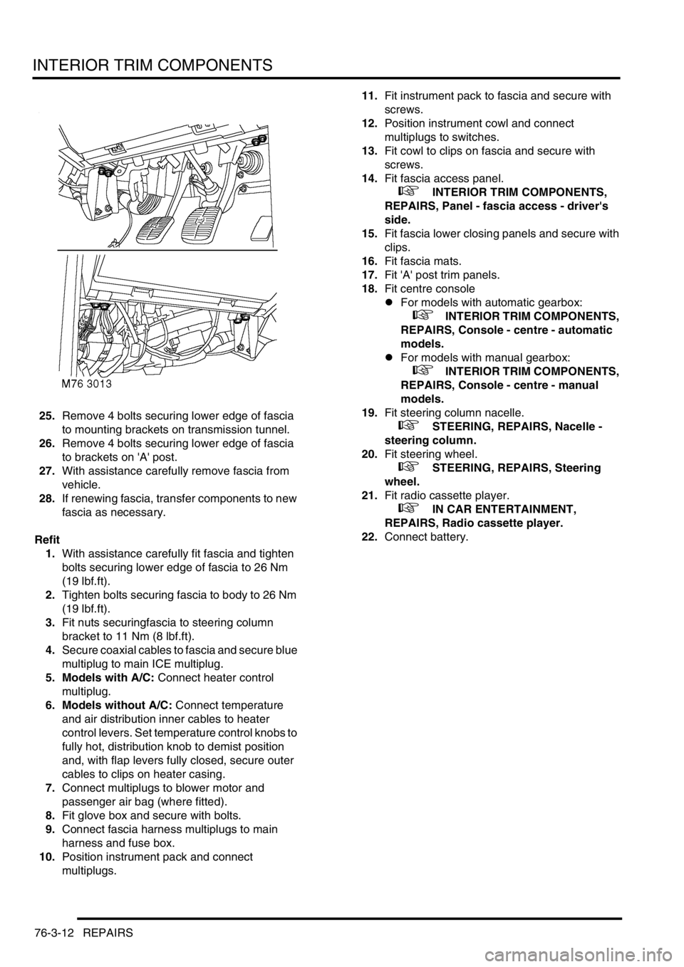
25.Remove 4 bolts securing lower edge of fascia
to mounting brackets on transmission tunnel.
26.Remove 4 bolts securing lower edge of fascia
to brackets on 'A' post.
27.With assistance carefully remove fascia from
vehicle.
28.If renewing fascia, transfer components to new
fascia as necessary.
Refit
1.With assistance carefully fit fascia and tighten
bolts securing lower edge of fascia to 26 Nm
(19 lbf.ft).
2.Tighten bolts securing fascia to body to 26 Nm
(19 lbf.ft).
3.Fit nuts securingfascia to steering column
bracket to 11 Nm (8 lbf.ft).
4.Secure coaxial cables to fascia and secure blue
multiplug to main ICE multiplug.
5. Models with A/C: Connect heater control
multiplug.
6. Models without A/C: Connect temperature
and air distribution inner cables to heater
control levers. Set temperature control knobs to
fully hot, distribution knob to demist position
and, with flap levers fully closed, secure outer
cables to clips on heater casing.
7.Connect multiplugs to blower motor and
passenger air bag (where fitted).
8.Fit glove box and secure with bolts.
9.Connect fascia harness multiplugs to main
harness and fuse box.
10.Position instrument pack and connect
multiplugs.11.Fit instrument pack to fascia and secure with
screws.
12.Position instrument cowl and connect
multiplugs to switches.
13.Fit cowl to clips on fascia and secure with
screws.
14.Fit fascia access panel.
+ INTERIOR TRIM COMPONENTS,
REPAIRS, Panel - fascia access - driver's
side.
15.Fit fascia lower closing panels and secure with
clips.
16.Fit fascia mats.
17.Fit 'A' post trim panels.
18.Fit centre console
lFor models with automatic gearbox:
+ INTERIOR TRIM COMPONENTS,
REPAIRS, Console - centre - automatic
models.
lFor models with manual gearbox:
+ INTERIOR TRIM COMPONENTS,
REPAIRS, Console - centre - manual
models.
19.Fit steering column nacelle.
+ STEERING, REPAIRS, Nacelle -
steering column.
20.Fit steering wheel.
+ STEERING, REPAIRS, Steering
wheel.
21.Fit radio cassette player.
+ IN CAR ENTERTAINMENT,
REPAIRS, Radio cassette player.
22.Connect battery.
Page 1168 of 1672
INTERIOR TRIM COMPONENTS
REPAIRS 76-3-15
Louvre panel assembly - centre fascia
$% 76.46.42
Remove
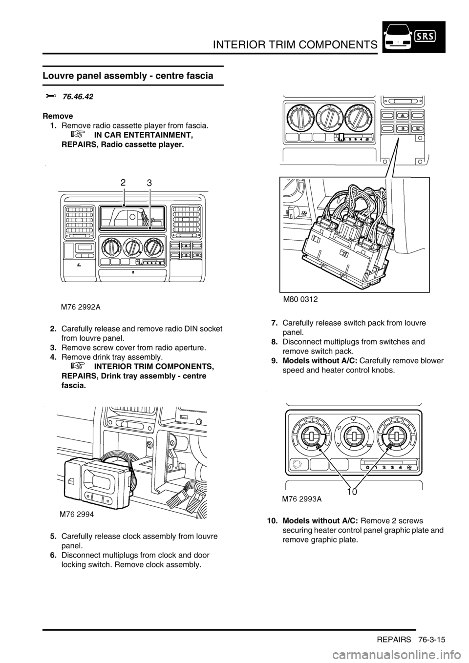
1.Remove radio cassette player from fascia.
+ IN CAR ENTERTAINMENT,
REPAIRS, Radio cassette player.
2.Carefully release and remove radio DIN socket
from louvre panel.
3.Remove screw cover from radio aperture.
4.Remove drink tray assembly.
+ INTERIOR TRIM COMPONENTS,
REPAIRS, Drink tray assembly - centre
fascia.
5.Carefully release clock assembly from louvre
panel.
6.Disconnect multiplugs from clock and door
locking switch. Remove clock assembly.7.Carefully release switch pack from louvre
panel.
8.Disconnect multiplugs from switches and
remove switch pack.
9. Models without A/C: Carefully remove blower
speed and heater control knobs.
10. Models without A/C: Remove 2 screws
securing heater control panel graphic plate and
remove graphic plate.