steering wheel adjustment LAND ROVER DISCOVERY 2002 User Guide
[x] Cancel search | Manufacturer: LAND ROVER, Model Year: 2002, Model line: DISCOVERY, Model: LAND ROVER DISCOVERY 2002Pages: 1672, PDF Size: 46.1 MB
Page 910 of 1672
STEERING
ADJUSTMENTS 57-23
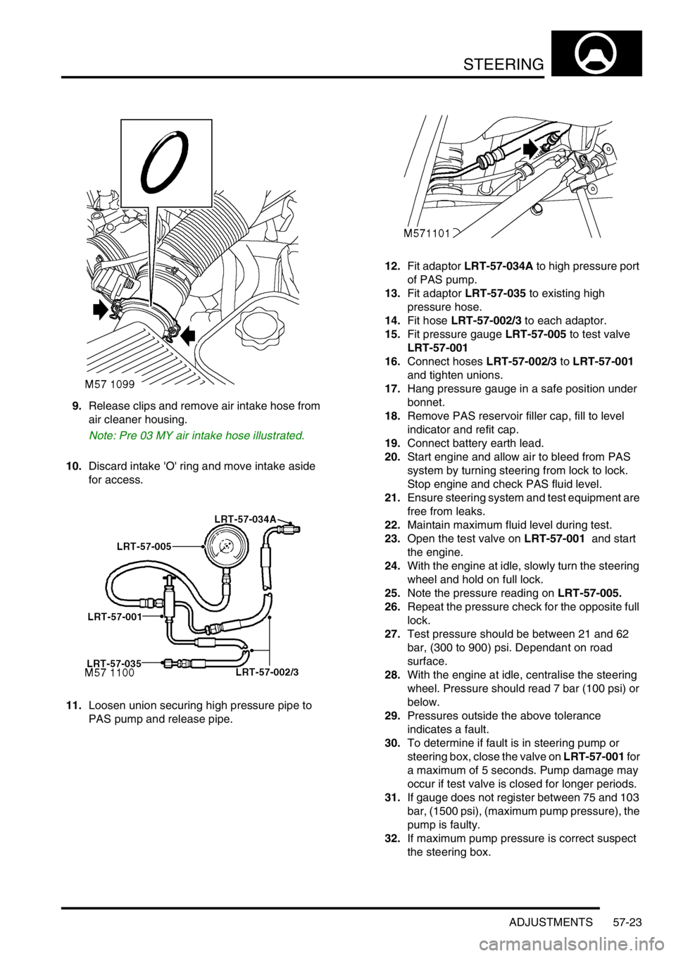
9.Release clips and remove air intake hose from
air cleaner housing.
Note: Pre 03 MY air intake hose illustrated.
10.Discard intake 'O' ring and move intake aside
for access.
11.Loosen union securing high pressure pipe to
PAS pump and release pipe.12.Fit adaptor LRT-57-034A to high pressure port
of PAS pump.
13.Fit adaptor LRT-57-035 to existing high
pressure hose.
14.Fit hose LRT-57-002/3 to each adaptor.
15.Fit pressure gauge LRT-57-005 to test valve
LRT-57-001
16.Connect hoses LRT-57-002/3 to LRT-57-001
and tighten unions.
17.Hang pressure gauge in a safe position under
bonnet.
18.Remove PAS reservoir filler cap, fill to level
indicator and refit cap.
19.Connect battery earth lead.
20.Start engine and allow air to bleed from PAS
system by turning steering from lock to lock.
Stop engine and check PAS fluid level.
21.Ensure steering system and test equipment are
free from leaks.
22.Maintain maximum fluid level during test.
23.Open the test valve on LRT-57-001 and start
the engine.
24.With the engine at idle, slowly turn the steering
wheel and hold on full lock.
25.Note the pressure reading on LRT-57-005.
26.Repeat the pressure check for the opposite full
lock.
27.Test pressure should be between 21 and 62
bar, (300 to 900) psi. Dependant on road
surface.
28.With the engine at idle, centralise the steering
wheel. Pressure should read 7 bar (100 psi) or
below.
29.Pressures outside the above tolerance
indicates a fault.
30.To determine if fault is in steering pump or
steering box, close the valve on LRT-57-001 for
a maximum of 5 seconds. Pump damage may
occur if test valve is closed for longer periods.
31.If gauge does not register between 75 and 103
bar, (1500 psi), (maximum pump pressure), the
pump is faulty.
32.If maximum pump pressure is correct suspect
the steering box.
Page 912 of 1672
STEERING
ADJUSTMENTS 57-25
7.Syphon PAS fluid from reservoir.
8.Position container to collect PAS fluid spillage.
9.Clean steering box pipe pipe housing.
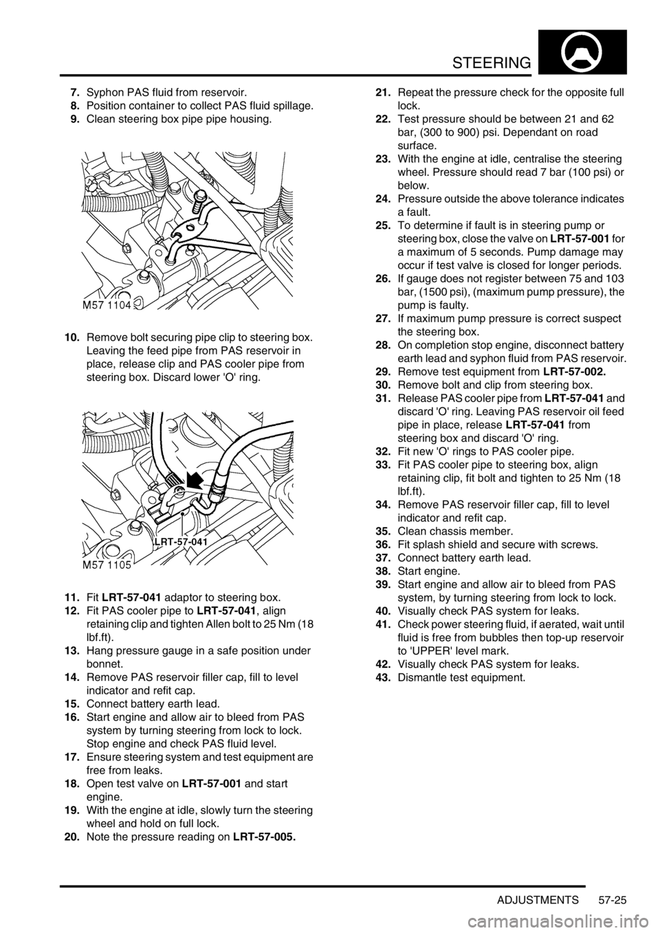
10.Remove bolt securing pipe clip to steering box.
Leaving the feed pipe from PAS reservoir in
place, release clip and PAS cooler pipe from
steering box. Discard lower 'O' ring.
11.Fit LRT-57-041 adaptor to steering box.
12.Fit PAS cooler pipe to LRT-57-041, align
retaining clip and tighten Allen bolt to 25 Nm (18
lbf.ft).
13.Hang pressure gauge in a safe position under
bonnet.
14.Remove PAS reservoir filler cap, fill to level
indicator and refit cap.
15.Connect battery earth lead.
16.Start engine and allow air to bleed from PAS
system by turning steering from lock to lock.
Stop engine and check PAS fluid level.
17.Ensure steering system and test equipment are
free from leaks.
18.Open test valve on LRT-57-001 and start
engine.
19.With the engine at idle, slowly turn the steering
wheel and hold on full lock.
20.Note the pressure reading on LRT-57-005.21.Repeat the pressure check for the opposite full
lock.
22.Test pressure should be between 21 and 62
bar, (300 to 900) psi. Dependant on road
surface.
23.With the engine at idle, centralise the steering
wheel. Pressure should read 7 bar (100 psi) or
below.
24.Pressure outside the above tolerance indicates
a fault.
25.To determine if fault is in steering pump or
steering box, close the valve on LRT-57-001 for
a maximum of 5 seconds. Pump damage may
occur if test valve is closed for longer periods.
26.If gauge does not register between 75 and 103
bar, (1500 psi), (maximum pump pressure), the
pump is faulty.
27.If maximum pump pressure is correct suspect
the steering box.
28.On completion stop engine, disconnect battery
earth lead and syphon fluid from PAS reservoir.
29.Remove test equipment from LRT-57-002.
30.Remove bolt and clip from steering box.
31.Release PAS cooler pipe from LRT-57-041 and
discard 'O' ring. Leaving PAS reservoir oil feed
pipe in place, release LRT-57-041 from
steering box and discard 'O' ring.
32.Fit new 'O' rings to PAS cooler pipe.
33.Fit PAS cooler pipe to steering box, align
retaining clip, fit bolt and tighten to 25 Nm (18
lbf.ft).
34.Remove PAS reservoir filler cap, fill to level
indicator and refit cap.
35.Clean chassis member.
36.Fit splash shield and secure with screws.
37.Connect battery earth lead.
38.Start engine.
39.Start engine and allow air to bleed from PAS
system, by turning steering from lock to lock.
40.Visually check PAS system for leaks.
41.Check power steering fluid, if aerated, wait until
fluid is free from bubbles then top-up reservoir
to 'UPPER' level mark.
42.Visually check PAS system for leaks.
43.Dismantle test equipment.
Page 916 of 1672

STEERING
REPAIRS 57-29
12. RH drive models with ACE: Position ACE
control arms to access steering box bolts.
13.With assistance remove 4 securing bolts and
remove steering box.
14.Remove centralising bolt from steering box. Refit
1.Fit centralising bolt to steering box.
2. With assistance, position steering box, fit bolts
and tighten to 90 Nm (66 lbf.ft).
3. RH drive models with ACE: Ensure washer is
in place on lower ball joint of anti-roll bar link,
then connect lower ball joint to axle. Tighten nut
to 100 Nm (74 lbf.ft).
4.Position drag link, fit nut and tighten to 80 Nm
(59 lbf.ft).
5.Position Panhard rod, fit bolt and nut and
tighten to 230 Nm (170 lbf.ft).
6.Clean PAS pipe ends and 'O' ring recess.
7.Lubricate new 'O' rings for PAS pipes with clean
PAS fluid.
8.Fit 'O' rings to PAS pipes and position pipes in
steering box. Fit PAS pipe bracket and tighten
bolt to 22 Nm (16 lbf.ft).
9. RHD models: Fit oil filter and housing:
lClean oil filter housing and engine mating
faces.
lLubricate new 'O' ring with clean engine oil
and fit to housing.
lPosition oil filter housing and tighten bolts to
9 Nm (7 lbf.ft).
10.Ensure steering wheel is centralised. Fit
universal joint between steering box and
intermediate shaft and tighten bolts to 25 Nm
(18 lbf.ft).
11.Remove centralising bolt from steering box.
12.Fit road wheel(s) and tighten nuts to 140 Nm
(103 lbf.ft)..
13.Remove stand(s) and lower vehicle.
14.Check and top up engine oil.
15.Bleed PAS system.
+ STEERING, ADJUSTMENTS,
Hydraulic system - bleed.
16.Centralise steering linkage
+ STEERING, ADJUSTMENTS,
Steering linkage - centralise.
Page 917 of 1672
STEERING
57-30 REPAIRS
Power steering box - LHD - diesel
$% 57.10.01
Remove
1.Remove battery cover.
2.Disconnect battery earth lead.
3.Drain cooling system.
+ COOLING SYSTEM - Td5,
ADJUSTMENTS, Drain and refill.
4.Raise front of vehicle.
WARNING: Do not work on or under a
vehicle supported only by a jack. Always
support the vehicle on safety stands.
5.Remove LH front road wheel.
6.Ensure steering wheel is centralised, remove
key from steering lock and engage column lock.
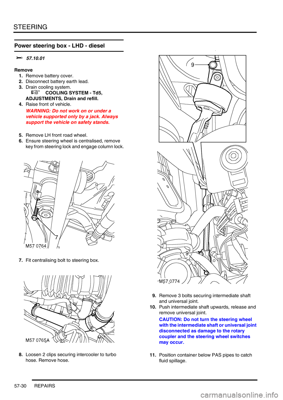
7.Fit centralising bolt to steering box.
8.Loosen 2 clips securing intercooler to turbo
hose. Remove hose.9.Remove 3 bolts securing intermediate shaft
and universal joint.
10.Push intermediate shaft upwards, release and
remove universal joint.
CAUTION: Do not turn the steering wheel
with the intermediate shaft or universal joint
disconnected as damage to the rotary
coupler and the steering wheel switches
may occur.
11.Position container below PAS pipes to catch
fluid spillage.
Page 920 of 1672

STEERING
REPAIRS 57-33
21.With assistance remove 2 nuts and bolts
securing RH engine mounting to chassis.
22.Support the engine weight on a jack.
CAUTION: To prevent damage to
components, cushion the jack pad with a
block of wood or hard rubber.
23.Raise the engine sufficiently to allow the
steering box to clear the sump.
24. Models with ACE: Position ACE control arms
to access steering box bolts. 25.With assistance remove 4 bolts securing
steering box and remove steering box.
26.Remove centralising bolt from steering box.
Refit
1.Fit centralising bolt to steering box.
2.With assistance, position steering box, fit bolts
and tighten to 90 Nm (66 lbf.ft).
3.Lower the engine onto its mountings. Fit engine
mounting bolts and tighten to 85 Nm (63 lbf.ft).
4. Models with ACE: Ensure washer is in place
on lower ball joint of anti-roll bar link, then
connect lower ball joint to axle. Tighten nut to
100 Nm (74 lbf.ft).
5.Position drag link, fit nut and tighten to 80 Nm
(59 lbf.ft).
6.Position Panhard rod, fit bolt and nut and
tighten to 230 Nm (170 lbf.ft).
7.Position coolant rail and secure with clips and
bolt.
8.Fit coolant hoses and secure with clips.
9. Models with ACE: Fit and tighten bolt
securing ACE pipes to chassis.
10.Clean PAS pipe ends and 'O' ring recess.
11.Lubricate new 'O' rings for PAS pipes with clean
PAS fluid.
12.Fit 'O' rings to PAS pipes and position pipes in
steering box. Fit PAS pipe bracket and tighten
bolt to 22 Nm (16 lbf.ft).
13.Ensure steering wheel is centralised. Fit
universal joint between steering box and
intermediate shaft and tighten bolts to 25 Nm
(18 lbf.ft).
14.Remove centralising bolt from steering box.
15.Fit intercooler to turbo hose and secure with
clips.
16.Fit road wheel(s) and tighten nuts to 140 Nm
(103 lbf.ft).
17.Remove stand(s) and lower vehicle.
18.Connect battery earth lead.
19.Fit battery cover.
20.Refill cooling system.
+ COOLING SYSTEM - Td5,
ADJUSTMENTS, Drain and refill.
21.Bleed PAS system.
+ STEERING, ADJUSTMENTS,
Hydraulic system - bleed.
22.Centralise steering linkage
+ STEERING, ADJUSTMENTS,
Steering linkage - centralise.
Page 921 of 1672
STEERING
57-34 REPAIRS
Steering box - RHD - diesel
$% 57.10.01
Remove
1.Remove battery cover.
2.Disconnect battery earth lead.
3.Drain cooling system.
+ COOLING SYSTEM - Td5,
ADJUSTMENTS, Drain and refill.
4.Raise front of vehicle.
WARNING: Do not work on or under a
vehicle supported only by a jack. Always
support the vehicle on safety stands.
5.Remove RH front road wheel.
6.Ensure steering wheel is centralised, remove
key from steering lock and engage column lock.
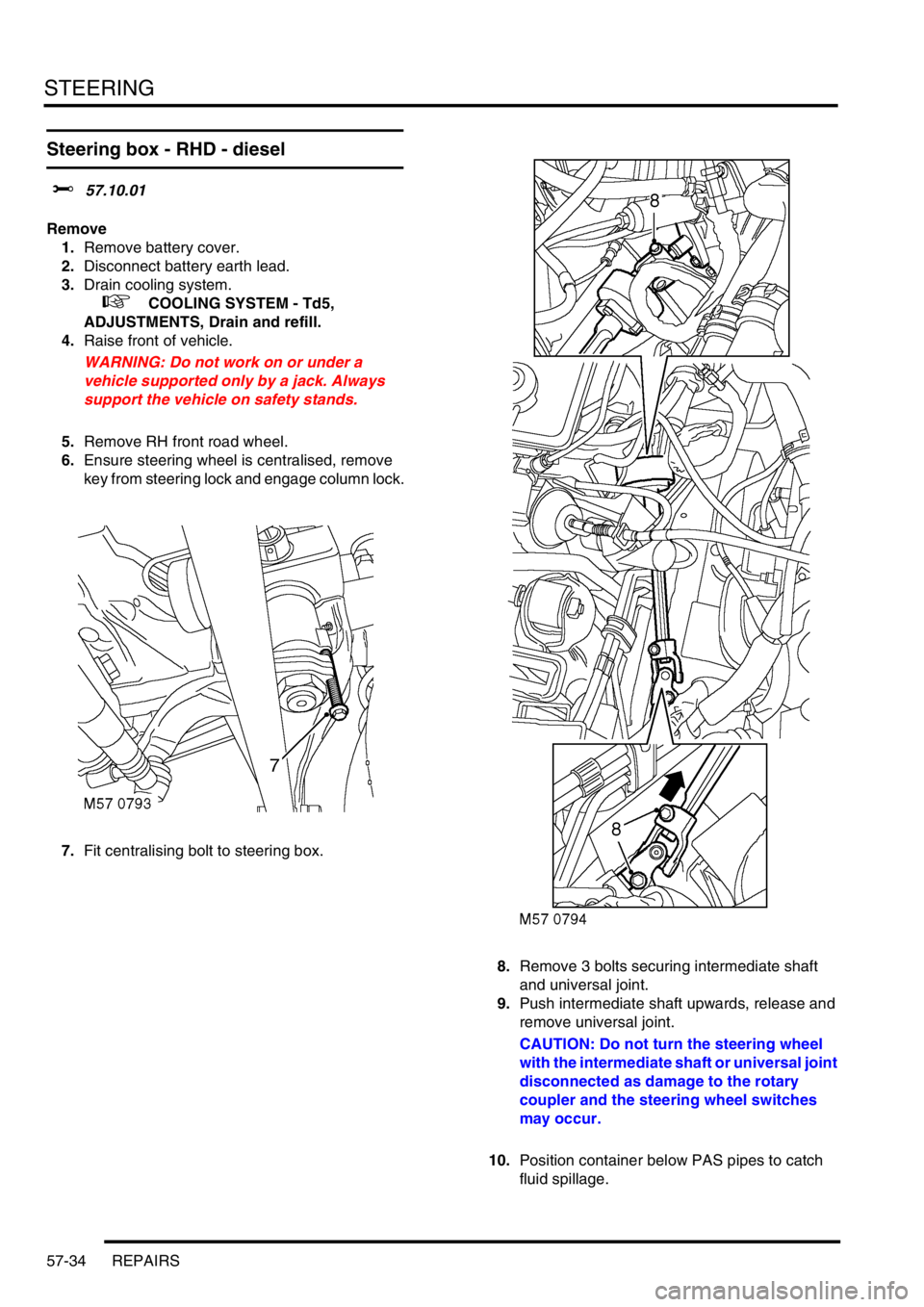
7.Fit centralising bolt to steering box.
8.Remove 3 bolts securing intermediate shaft
and universal joint.
9.Push intermediate shaft upwards, release and
remove universal joint.
CAUTION: Do not turn the steering wheel
with the intermediate shaft or universal joint
disconnected as damage to the rotary
coupler and the steering wheel switches
may occur.
10.Position container below PAS pipes to catch
fluid spillage.
Page 924 of 1672

STEERING
REPAIRS 57-37
10.Lubricate new 'O' rings for PAS pipes with
clean PAS fluid.
11.Fit 'O' rings to PAS pipes and position pipes in
steering box. Fit PAS pipe bracket and tighten
bolt to 22 Nm 16 lbf.ft).
12.Ensure steering wheel is centralised. Fit
universal joint between steering box and
intermediate shaft and tighten bolts to 25 Nm
(18 lbf.ft).
13.Remove centralising bolt from steering box.
14.Fit road wheel(s) and tighten nuts to 140 Nm
(103 lbf.ft).
15.Remove stand(s) and lower vehicle.
16.Connect battery earth lead.
17.Fit battery cover.
18.Refill cooling system.
+ COOLING SYSTEM - Td5,
ADJUSTMENTS, Drain and refill.
19.Bleed PAS system.
+ STEERING, ADJUSTMENTS,
Hydraulic system - bleed.
20.Centralise steering linkage
+ STEERING, ADJUSTMENTS,
Steering linkage - centralise.
Seal - input shaft - steering box
$% 57.10.16
Remove
1.Remove steering box:
lFor V8 models:
+ STEERING, REPAIRS, Power
steering box - V8.
lFor LHD diesel models:
+ STEERING, REPAIRS, Power
steering box - LHD - diesel.
lFor RHD diesel models:
+ STEERING, REPAIRS, Steering
box - RHD - diesel.
2.Secure steering box in vice.
3.Remove circlip and extract oil seal from
steering box. Take care not to damage
surface of the shaft.
Refit
1.Clean oil seal recess and input shaft.
2.Lubricate new seal with clean PAS fluid.
3.Fit seal using LRT-57-503.
4.Fit circlip.
5.Fit steering box.
lFor V8 models:
+ STEERING, REPAIRS, Power
steering box - V8.
lFor LHD diesel models:
+ STEERING, REPAIRS, Power
steering box - LHD - diesel.
lFor RHD diesel models:
+ STEERING, REPAIRS, Steering
box - RHD - diesel.
Page 935 of 1672
STEERING
57-48 REPAIRS
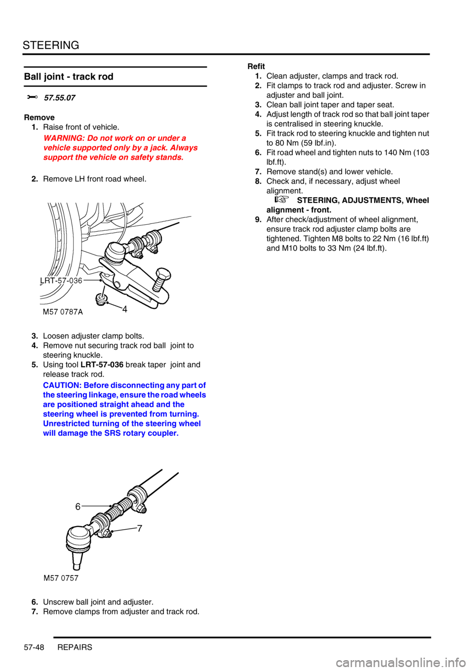
Ball joint - track rod
$% 57.55.07
Remove
1.Raise front of vehicle.
WARNING: Do not work on or under a
vehicle supported only by a jack. Always
support the vehicle on safety stands.
2.Remove LH front road wheel.
3.Loosen adjuster clamp bolts.
4.Remove nut securing track rod ball joint to
steering knuckle.
5.Using tool LRT-57-036 break taper joint and
release track rod.
CAUTION: Before disconnecting any part of
the steering linkage, ensure the road wheels
are positioned straight ahead and the
steering wheel is prevented from turning.
Unrestricted turning of the steering wheel
will damage the SRS rotary coupler.
6.Unscrew ball joint and adjuster.
7.Remove clamps from adjuster and track rod. Refit
1.Clean adjuster, clamps and track rod.
2.Fit clamps to track rod and adjuster. Screw in
adjuster and ball joint.
3.Clean ball joint taper and taper seat.
4.Adjust length of track rod so that ball joint taper
is centralised in steering knuckle.
5.Fit track rod to steering knuckle and tighten nut
to 80 Nm (59 lbf.in).
6.Fit road wheel and tighten nuts to 140 Nm (103
lbf.ft).
7.Remove stand(s) and lower vehicle.
8.Check and, if necessary, adjust wheel
alignment.
+ STEERING, ADJUSTMENTS, Wheel
alignment - front.
9.After check/adjustment of wheel alignment,
ensure track rod adjuster clamp bolts are
tightened. Tighten M8 bolts to 22 Nm (16 lbf.ft)
and M10 bolts to 33 Nm (24 lbf.ft).
Page 936 of 1672
STEERING
REPAIRS 57-49
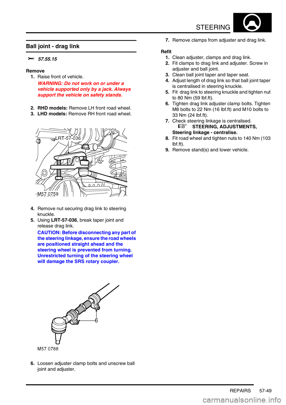
Ball joint - drag link
$% 57.55.15
Remove
1.Raise front of vehicle.
WARNING: Do not work on or under a
vehicle supported only by a jack. Always
support the vehicle on safety stands.
2. RHD models: Remove LH front road wheel.
3. LHD models: Remove RH front road wheel.
4.Remove nut securing drag link to steering
knuckle.
5.Using LRT-57-036, break taper joint and
release drag link.
CAUTION: Before disconnecting any part of
the steering linkage, ensure the road wheels
are positioned straight ahead and the
steering wheel is prevented from turning.
Unrestricted turning of the steering wheel
will damage the SRS rotary coupler.
6.Loosen adjuster clamp bolts and unscrew ball
joint and adjuster. 7.Remove clamps from adjuster and drag link.
Refit
1.Clean adjuster, clamps and drag link.
2.Fit clamps to drag link and adjuster. Screw in
adjuster and ball joint.
3.Clean ball joint taper and taper seat.
4.Adjust length of drag link so that ball joint taper
is centralised in steering knuckle.
5.Fit drag link to steering knuckle and tighten nut
to 80 Nm (59 lbf.ft).
6.Tighten drag link adjuster clamp bolts. Tighten
M8 bolts to 22 Nm (16 lbf.ft) and M10 bolts to
33 Nm (24 lbf.ft).
7.Check steering linkage is centralised.
+ STEERING, ADJUSTMENTS,
Steering linkage - centralise.
8.Fit road wheel and tighten nuts to 140 Nm (103
lbf.ft).
9.Remove stand(s) and lower vehicle.
Page 937 of 1672
STEERING
57-50 REPAIRS
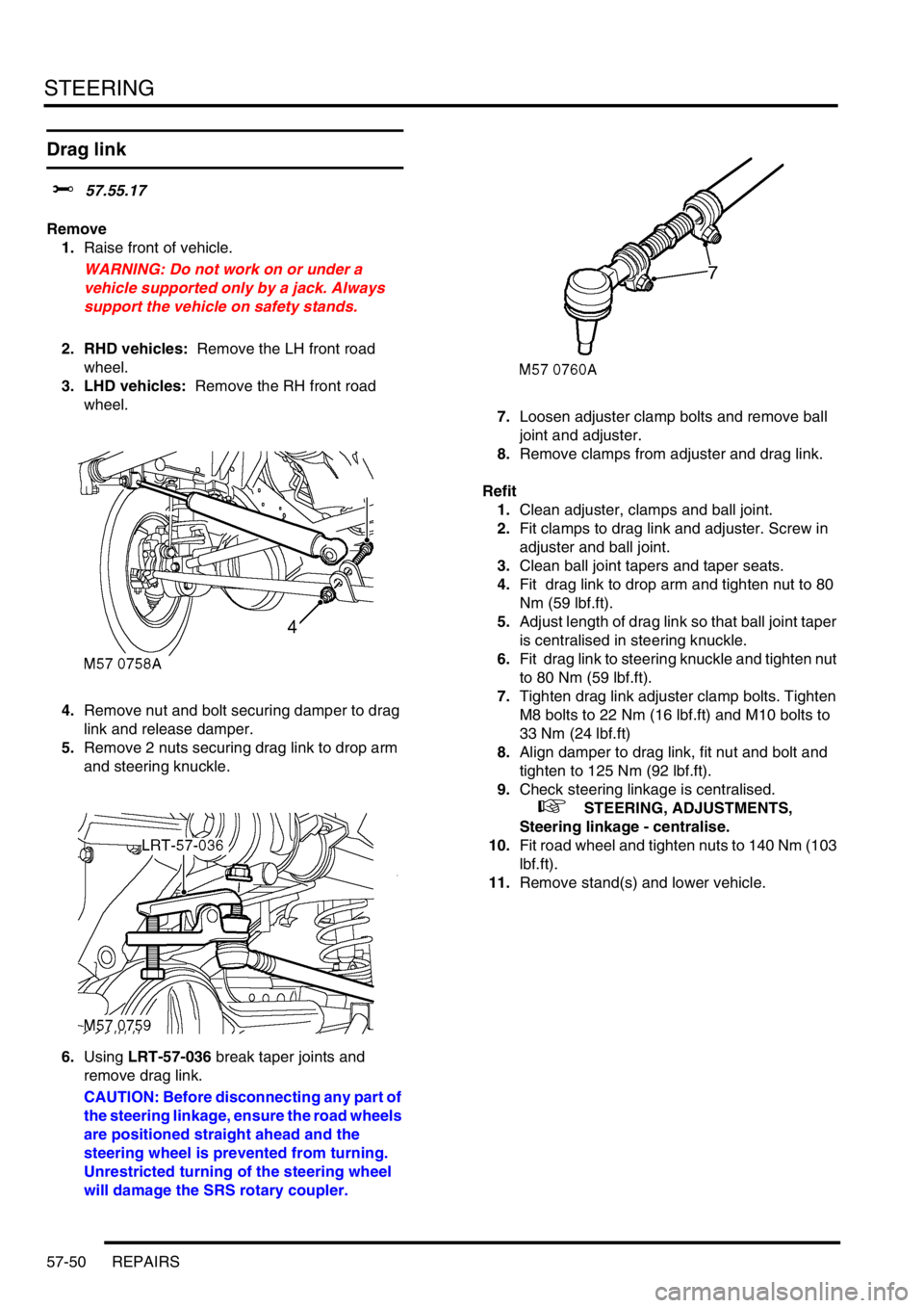
Drag link
$% 57.55.17
Remove
1.Raise front of vehicle.
WARNING: Do not work on or under a
vehicle supported only by a jack. Always
support the vehicle on safety stands.
2. RHD vehicles: Remove the LH front road
wheel.
3. LHD vehicles: Remove the RH front road
wheel.
4.Remove nut and bolt securing damper to drag
link and release damper.
5.Remove 2 nuts securing drag link to drop arm
and steering knuckle.
6.Using LRT-57-036 break taper joints and
remove drag link.
CAUTION: Before disconnecting any part of
the steering linkage, ensure the road wheels
are positioned straight ahead and the
steering wheel is prevented from turning.
Unrestricted turning of the steering wheel
will damage the SRS rotary coupler.7.Loosen adjuster clamp bolts and remove ball
joint and adjuster.
8.Remove clamps from adjuster and drag link.
Refit
1.Clean adjuster, clamps and ball joint.
2.Fit clamps to drag link and adjuster. Screw in
adjuster and ball joint.
3.Clean ball joint tapers and taper seats.
4.Fit drag link to drop arm and tighten nut to 80
Nm (59 lbf.ft).
5.Adjust length of drag link so that ball joint taper
is centralised in steering knuckle.
6.Fit drag link to steering knuckle and tighten nut
to 80 Nm (59 lbf.ft).
7.Tighten drag link adjuster clamp bolts. Tighten
M8 bolts to 22 Nm (16 lbf.ft) and M10 bolts to
33 Nm (24 lbf.ft)
8.Align damper to drag link, fit nut and bolt and
tighten to 125 Nm (92 lbf.ft).
9.Check steering linkage is centralised.
+ STEERING, ADJUSTMENTS,
Steering linkage - centralise.
10.Fit road wheel and tighten nuts to 140 Nm (103
lbf.ft).
11.Remove stand(s) and lower vehicle.