washer fluid LAND ROVER DISCOVERY 2002 Workshop Manual
[x] Cancel search | Manufacturer: LAND ROVER, Model Year: 2002, Model line: DISCOVERY, Model: LAND ROVER DISCOVERY 2002Pages: 1672, PDF Size: 46.1 MB
Page 5 of 1672

CONTENTS
2CONTENTS
IDENTIFICATION NUMBERS .................................................................. 05-1
Vehicle Identification Number ......................................................................................................... 05-1
Identification Number Locations ..................................................................................................... 05-3
TORQUE WRENCH SETTINGS .............................................................. 06-1
Maintenance ................................................................................................................................... 06-1
Engine Td5 ..................................................................................................................................... 06-2
Engine V8 ....................................................................................................................................... 06-4
Emission control - Td5 .................................................................................................................... 06-5
Emission control - V8 ...................................................................................................................... 06-5
Engine management system - Td5 ................................................................................................. 06-5
Engine management system - V8................................................................................................... 06-6
Cooling system ............................................................................................................................... 06-6
Manifolds and exhaust systems - Td5 ............................................................................................ 06-6
Manifolds and exhaust systems - V8 .............................................................................................. 06-7
Clutch.............................................................................................................................................. 06-7
Manual gearbox - R380 .................................................................................................................. 06-8
Transfer box - LT230SE ................................................................................................................. 06-8
Automatic gearbox - ZF4HP22/24 .................................................................................................. 06-9
Propeller shafts ............................................................................................................................... 06-9
Axles ............................................................................................................................................... 06-9
Steering .......................................................................................................................................... 06-10
Front suspension ............................................................................................................................ 06-11
Rear suspension ............................................................................................................................. 06-12
Brakes............................................................................................................................................. 06-12
Restraint systems ........................................................................................................................... 06-13
Body................................................................................................................................................ 06-14
Heating and air conditioning ........................................................................................................... 06-15
Wipers and washers ....................................................................................................................... 06-15
Electrical ......................................................................................................................................... 06-15
LIFTING AND TOWING ........................................................................... 08-1
LIFTING .......................................................................................................................................... 08-1
TOWING ......................................................................................................................................... 08-2
TRANSPORTING ........................................................................................................................... 08-3
CAPACITIES, FLUIDS AND LUBRICANTS ............................................ 09-1
Capacities ....................................................................................................................................... 09-1
Fluids .............................................................................................................................................. 09-2
Anti-Freeze Concentration .............................................................................................................. 09-3
Lubrication ...................................................................................................................................... 09-3
MAINTENANCE ........................................................................................ 10-1
PROCEDURES
V8 engine underbonnet view .......................................................................................................... 10-1
Diesel underbonnet view ................................................................................................................ 10-2
Seats and seat belts ...................................................................................................................... 10-3
Lamps, horns and warning indicators ........................................................................................... 10-5
Wipers and washers ...................................................................................................................... 10-5
Handbrake .................................................................................................................................. 10-6
Page 36 of 1672
GENERAL INFORMATION
03-1
GENERAL INFORMATION
General Precautions
Dangerous substances
Modern vehicles contain many materials and liquids
which if not handled with care can be hazardous to
both personal health and the environment.
WARNING: Many liquids and other substances
used in motor vehicles are poisonous and should
under no circumstances be consumed and
should, as far as possible, be kept from contact
with the skin. These liquids and substances
include acid, anti-freeze, asbestos, brake fluid,
fuel, windscreen washer additives, lubricants,
refrigerants and various adhesives.
Always read carefully the instructions printed on
labels or stamped on components and obey them
implicitly. Such instructions are included for
reasons of your health and personal safety.
Never disregard them.
Synthetic rubber
Many 'O' rings, seals, hoses, flexible pipes and other
similar items which appear to be natural rubber, are
in fact, made of synthetic materials called
Fluoroelastomers. Under normal operating
conditions this material is safe and does not present
a health hazard. However, if the material is damaged
by fire or excessive heating, it can break down and
produce highly corrosive Hydrofluoric acid.
Contact with Hydrofluoric acid can cause serious
burns on contact with skin. If skin contact does occur:
lRemove any contaminated clothing
immediately.
lIrrigate effected area of skin with a copious
amount of cold water or limewater for 15 to 60
minutes.
lObtain medical assistance immediately.
Should any material be in a burnt or overheated
condition, handle with extreme caution and wear
protective clothing (seamless industrial gloves,
protective apron etc.).
Decontaminate and dispose of gloves immediately
after use.Lubricating oils
Avoid excessive skin contact with used lubricating
oils and always adhere to the health protection
precautions.
WARNING: Avoid excessive skin contact with
used engine oil. Used engine oil contains
potentially harmful contaminants which may
cause skin cancer or other serious skin
disorders.
WARNING: Avoid excessive skin contact with
mineral oil. Mineral oils remove the natural fats
from the skin, leading to dryness, irritation and
dermatitis.
Health protection precautions
The following precautions should be observed at all
times.
lWear protective clothing, including impervious
gloves where practicable.
lAvoid prolonged and repeated contact with oils,
particularly used engine oils.
lDo not put oily rags in pockets.
lAvoid contaminating clothes (particularly those
next to the skin) with oil.
lOveralls must be cleaned regularly. Discard
heavily soiled clothing and oil impregnated
footwear.
lFirst aid treatment should be obtained
immediately for open cuts and wounds.
lApply barrier creams before each work period to
help prevent lubricating oil from contaminating
the skin.
lWash with soap and water to ensure all oil is
removed (proprietary skin cleansers and nail
brushes will help).
lUse moisturisers after cleaning; preparations
containing lanolin help replace the skin's natural
oils which have been removed.
lDo not use petrol/gasoline, kerosene, diesel
fuel, oil, thinners or solvents for cleaning skin.
lWhere practicable, degrease components prior
to handling.
lIf skin disorders develop, obtain medical advice
without delay.
lWear eye protection (e.g. goggles or face
shield) if there is a risk of eye contamination.
Eye wash facilities should be provided in close
vicinity of the work area.
Page 61 of 1672
GENERAL INFORMATION
03-26
Air Conditioning Compressor
Replacement
A new compressor is supplied filled with a full charge
(X cm3) of refrigerant oil.
+ CAPACITIES, FLUIDS AND
LUBRICANTS, Capacities.A calculated quantity of
oil must be drained from the new compressor before
fitting. To calculate the quantity of oil to be drained:
1Remove the drain plug from the old
compressor.
2Invert the compressor and gravity drain the oil
into a calibrated measuring cylinder. Rotate the
compressor clutch to ensure the compressor is
completely drained.
3Note the quantity of oil drained (Y cm
3).
4Calculate the quantity of oil to be drained from
the new compressor using the following
formula:
X cm
3 — (Y cm3 + 20 cm3) = Q cm3
5Remove the drain plug from the new
compressor and drain Q cm3 of oil. Fit and
tighten the compressor drain plug.
Body Repairs
General
Body shells are of welded construction and bolted to
a chassis frame. Front and rear sections of the shell
are designed as 'energy absorbing' zones. This
means they are designed to deform progressively
when subjected to impact in order to minimise the
likelihood of injury to vehicle occupants.
It is essential that design dimensions and strength
are restored in accident rectification. It is important
that neither structural weakness nor excessive local
stiffness are introduced into the vehicle during body
repair.
Repairs usually involve a combination of operations
ranging from straightening procedures to renewal of
individual panels or panel assemblies. The repairer
will determine the repair method and this decision will
take into account a balance of economics between
labour and material costs and the availability of repair
facilities in both equipment and skills. It may also
involve considerations of the vehicles' downtime,
replacement vehicle availability and repair turn-
around time.
It is expected that a repairer will select the best and
most economic repair method possible, making use
of the facilities available. The instructions given are
intended to assist a skilled body repairer by
expanding approved procedures for panel
replacement. The objective is to restore the vehicle
to a safe running condition by carrying out a repair
which is as close as is feasible to original standard.
The results should not advertise to the experienced
eye that the vehicle has been damaged, although the
repair might not be identical in all respects to the
original factory build. Commercial bodyshop repair
facilities cannot always duplicate methods of
construction used during production.
Operations covered in this Manual do not include
reference to testing the vehicle after repair. It is
essential that work is inspected and suspension
geometry checked after completion. Where
necessary a road test of the vehicle should be carried
out, particularly where safety-related items are
concerned.
Where major units have been disconnected or
removed it is necessary to ensure that fluid levels are
checked and topped up where necessary. It is also
necessary to ensure that the repaired vehicle is in a
roadworthy condition in respect of tyre pressures,
lights, washer fluid etc.
Page 110 of 1672
MAINTENANCE
PROCEDURES 10-1
MAINTENANCE PROCEDURES
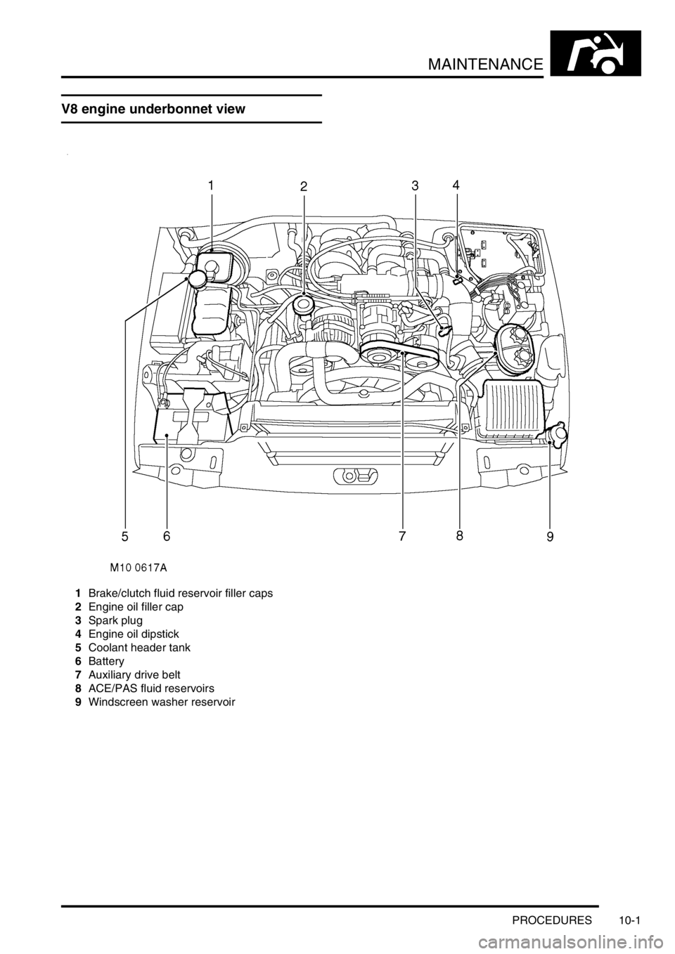
V8 engine underbonnet view
1Brake/clutch fluid reservoir filler caps
2Engine oil filler cap
3Spark plug
4Engine oil dipstick
5Coolant header tank
6Battery
7Auxiliary drive belt
8ACE/PAS fluid reservoirs
9Windscreen washer reservoir
Page 111 of 1672
MAINTENANCE
10-2 PROCEDURES
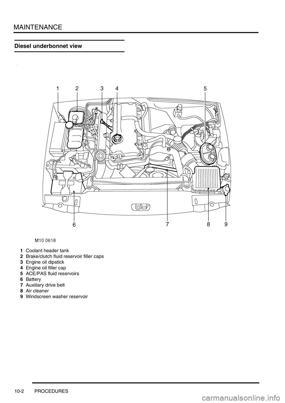
Diesel underbonnet view
1Coolant header tank
2Brake/clutch fluid reservoir filler caps
3Engine oil dipstick
4Engine oil filler cap
5ACE/PAS fluid reservoirs
6Battery
7Auxiliary drive belt
8Air cleaner
9Windscreen washer reservoir
Page 122 of 1672

MAINTENANCE
PROCEDURES 10-13
Check/top-up — Washer reservoir
1.Check fluid level in windscreen washer
reservoir.
2.Clean area around filler cap, remove cap.
3.Top-up if necessary to correct level on reservoir
using recommended fluid.
+ CAPACITIES, FLUIDS AND
LUBRICANTS, Fluids.
4.Fit filler cap.
Steering box
Check
1.Check steering box for fluid leaks.
Adjust
1.Check that there is no backlash in steering box
with road wheels in straight ahead position.
Adjust if required.
+ STEERING, ADJUSTMENTS,
Steering box - check and adjust.
Battery
Check
1.Check battery condition by checking colour of
condition indicator.
lGreen = O.K.
lBlack = Battery requires charging.
lClear/white = New battery required.
Clean
1.Clean and grease battery terminals with
petroleum jelly.
Page 123 of 1672

MAINTENANCE
10-14 PROCEDURES
Intercooler - diesel engine
Remove
1.Remove intercooler.
+ ENGINE MANAGEMENT SYSTEM -
Td5, REPAIRS, Intercooler.
Flush
1.Flush intercooler element using Flushing
Solvent Part No. STC 9713, following the
manufacturer's instructions.
2.Thoroughly dry intercooler ensuring that no
trace of solvent remains in the element.
3.Refit intercooler on completion.
+ ENGINE MANAGEMENT SYSTEM -
Td5, REPAIRS, Intercooler.
Engine oil - V8 engine
WARNING: Avoid excessive skin contact with
used engine oil. Used engine oil contains
potentially harmful contaminants which may
cause skin cancer or other serious skin
disorders.
Replace
1.Position suitable container beneath sump.
2.Clean area around oil drain plug.
3.Remove oil drain plug, discard sealing washer.
4.Allow oil to drain.
5.Fit new sealing washer to oil drain plug.
6.Fit engine drain plug and tighten to 33 Nm (24
lbf.ft).
7.Fill engine with recommended grade of oil to
correct mark on dipstick.
+ CAPACITIES, FLUIDS AND
LUBRICANTS, Lubrication.
Engine oil - diesel engine
WARNING: Avoid excessive skin contact with
used engine oil. Used engine oil contains
potentially harmful contaminants which may
cause skin cancer or other serious skin
disorders.
Replace
1.Release fixings, remove underbelly panel.
2.Position suitable container beneath sump.
3.Clean area around drain plug.
4.Remove oil drain plug, discard sealing washer.
5.Allow oil to drain.
6.Fit new sealing washer to oil drain plug.
7.Fit engine drain plug and tighten to 23 Nm (17
lbf.ft).
8.Fill engine with recommended grade of oil to
correct mark on dipstick.
+ CAPACITIES, FLUIDS AND
LUBRICANTS, Lubrication.
9.Fit front underbelly panel, secure fixings.
Page 125 of 1672

MAINTENANCE
10-16 PROCEDURES
Manual gearbox
WARNING: Avoid excessive skin contact with
mineral oil. Mineral oils remove the natural fats
from the skin, leading to dryness, irritation and
dermatitis.
Check/top-up oil level
1.Release fixings, remove rear underbelly panel.
2.Clean area around oil filler/level plug.
3.Remove oil filler/level plug.
4.Check that oil level is to bottom of oil filler/level
plug hole.
5.Top-up level (if required) with recommended oil
to bottom of filler/level plug hole.
+ CAPACITIES, FLUIDS AND
LUBRICANTS, Lubrication.
6.Remove all traces of sealant from threads of oil
filler/level plug.
7.Apply Loctite 290 to threads of oil filler/level
plug.
8. Fit manual gearbox filler/level plug and tighten
to 30 Nm (22 lbf.ft).
9.Remove all traces of oil from gearcase.
10.Fit rear underbelly panel, secure fixings.
Replace oil
1.Release fixings, remove rear underbelly panel.
2.Place a suitable container beneath gearbox
drain plug.
3.Clean area around oil filler/level and drain
plugs.4.Remove oil filler/level plug.
5.Remove oil drain plug, remove and discard
sealing washer.
6.Allow oil to drain.
7.Clean magnet in oil drain plug.
8.Fit new sealing washer to oil drain plug.
9.Fit manual gearbox drain plug and tighten to 50
Nm (37 lbf.ft).
10.Fill gearbox with recommended oil to bottom of
filler/level plug hole.
+ CAPACITIES, FLUIDS AND
LUBRICANTS, Lubrication.
11.Remove all traces of sealant from threads of oil
filler/level plug.
12.Apply Loctite 290 to threads of oil filler/level
plug.
13. Fit manual gearbox filler/level plug and tighten
to 30 Nm (22 lbf.ft).
14.Remove all traces of oil from gearcase.
15.Fit rear underbelly panel, secure fixings.
Page 126 of 1672
MAINTENANCE
PROCEDURES 10-17
Automatic gearbox
WARNING: Avoid excessive skin contact with
mineral oil. Mineral oils remove the natural fats
from the skin, leading to dryness, irritation and
dermatitis.
Replace oil filter
1.Replace oil filter.
+ AUTOMATIC GEARBOX - ZF4HP22
- 24, REPAIRS, Filter - oil.
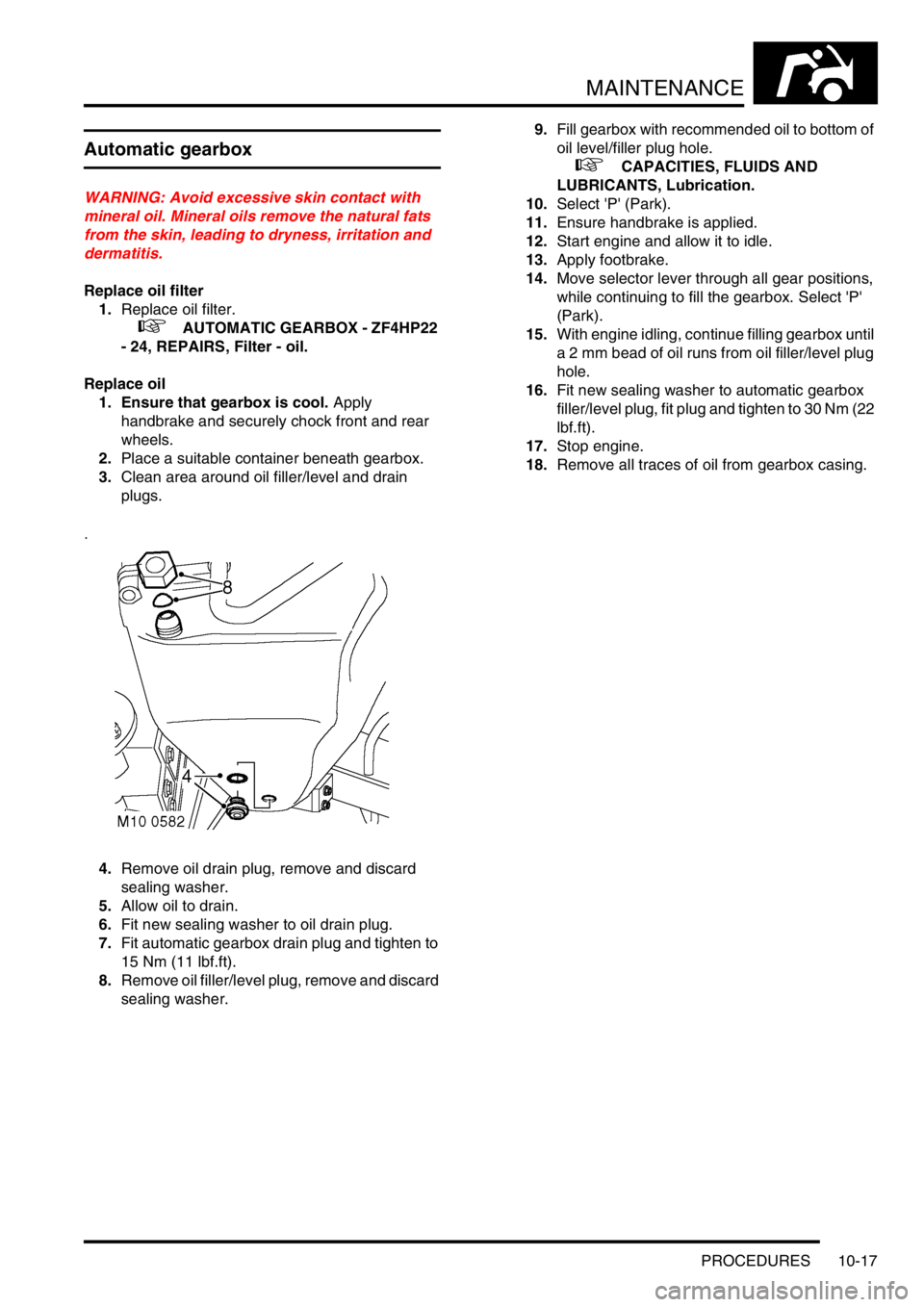
Replace oil
1. Ensure that gearbox is cool. Apply
handbrake and securely chock front and rear
wheels.
2.Place a suitable container beneath gearbox.
3.Clean area around oil filler/level and drain
plugs.
4.Remove oil drain plug, remove and discard
sealing washer.
5.Allow oil to drain.
6.Fit new sealing washer to oil drain plug.
7.Fit automatic gearbox drain plug and tighten to
15 Nm (11 lbf.ft).
8.Remove oil filler/level plug, remove and discard
sealing washer.9.Fill gearbox with recommended oil to bottom of
oil level/filler plug hole.
+ CAPACITIES, FLUIDS AND
LUBRICANTS, Lubrication.
10.Select 'P' (Park).
11.Ensure handbrake is applied.
12.Start engine and allow it to idle.
13.Apply footbrake.
14.Move selector lever through all gear positions,
while continuing to fill the gearbox. Select 'P'
(Park).
15.With engine idling, continue filling gearbox until
a 2 mm bead of oil runs from oil filler/level plug
hole.
16.Fit new sealing washer to automatic gearbox
filler/level plug, fit plug and tighten to 30 Nm (22
l b f . f t ) .
17.Stop engine.
18.Remove all traces of oil from gearbox casing.
Page 596 of 1672

COOLING SYSTEM - TD5
ADJUSTMENTS 26-1-13
ADJUST ME NTS
Drain and refill
$% 26.10.01
WARNING: Since injury such as scalding could
be caused by escaping steam or coolant, do not
remove the filler cap from the coolant expansion
tank while the system is hot.
Drain
1.Visually check engine and cooling system for
signs of coolant leaks.
2.Examine hoses for signs of cracking, distortion
and security of connections.
3.Position drain tray to collect coolant.
4.Remove expansion tank filler cap.
5.Remove drain plug access cover from
underbelly panel.
6.Remove drain plug from coolant pump feed
pipe and allow cooling system to drain. Discard
drain plug sealing washer.
Refill
1.Flush system with water under low pressure.
Do not use water under high pressure as it
could damage the radiator.
2.Fit new sealing washer to drain plug. Fit and
tighten drain plug in coolant pump feed pipe.
3.Fit access cover to underbelly panel.
4.Prepare coolant to required concentration.
+ CAPACITIES, FLUIDS AND
LUBRICANTS, Anti-Freeze Concentration.5.Remove bleed screw from top hose.
6.Unclip the bleed hose from the battery box.
7.Unclip the expansion tank from its mounting
bracket, remove the expansion tank cap and
raise the expansion tank vertically 10 cm (4 in).
Retain the tank in this position.
8.Slowly fill the system through the coolant
expansion tank until a steady flow of coolant is
emitted from the bleed hole.
9.Fit the bleed screw, then, with the expansion
tank still raised, continue filling the system until
coolant level reaches the cold level mark on
expansion tank.
10.Fit expansion tank filler cap, fit the expansion
tank to its mounting bracket and clip the bleed
hose to the battery box.
11.Start and run engine until normal operating
temperature is reached, and check for leaks.
12.Switch off engine and allow to cool.
13.Check for leaks and top-up coolant to the cold
level mark on expansion tank