charging LAND ROVER DISCOVERY 2002 Owner's Manual
[x] Cancel search | Manufacturer: LAND ROVER, Model Year: 2002, Model line: DISCOVERY, Model: LAND ROVER DISCOVERY 2002Pages: 1672, PDF Size: 46.1 MB
Page 641 of 1672

MANIFOLDS AND EXHAUST SYSTEMS - V8
30-2-12 REPAIRS
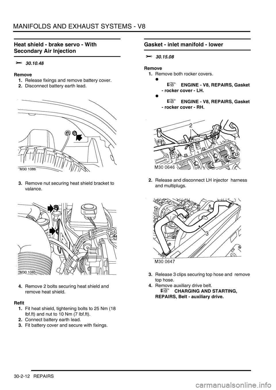
Heat shield - brake servo - With
Secondary Air Injection
$% 30.10.48
Remove
1.Release fixings and remove battery cover.
2.Disconnect battery earth lead.
3.Remove nut securing heat shield bracket to
valance.
4.Remove 2 bolts securing heat shield and
remove heat shield.
Refit
1.Fit heat shield, tightening bolts to 25 Nm (18
lbf.ft) and nut to 10 Nm (7 lbf.ft).
2.Connect battery earth lead.
3.Fit battery cover and secure with fixings.
Gasket - inlet manifold - lower
$% 30.15.08
Remove
1.Remove both rocker covers.
l
+ ENGINE - V8, REPAIRS, Gasket
- rocker cover - LH.
l
+ ENGINE - V8, REPAIRS, Gasket
- rocker cover - RH.
2.Release and disconnect LH injector harness
and multiplugs.
3.Release 3 clips securing top hose and remove
top hose.
4.Remove auxiliary drive belt.
+ CHARGING AND STARTING,
REPAIRS, Belt - auxiliary drive.
Page 644 of 1672

MANIFOLDS AND EXHAUST SYSTEMS - V8
REPAIRS 30-2-15
Refit
1.Clean old RTV sealant from cylinder head and
cylinder block notches.
2.Clean mating faces of cylinder block, cylinder
head and inlet manifold.
3.Apply RTV sealant to cylinder head and
cylinder block notches.
4.Fit new gasket seals, ensuring ends engage
correctly in notches.
5.Fit new inlet manifold gasket.
6.Position gasket clamps and fit bolts, but do not
tighten at this stage.
7.Position inlet manifold to engine. Fit manifold
bolts and, working in the sequence shown,
tighten bolts initially to 10 Nm (7 lbf.ft) then to
51 Nm (38 lbf.ft).
8.Tighten gasket clamp bolts to 18 Nm (13 lbf.ft).
9.Connect fuel pipe.
10.Clean top hose outlet pipe mating faces.
11.Fit new 'O' ring to outlet pipe.
12.Position outlet pipe, fit bolts and tighten to 22
Nm (16 lbf.ft).
13.Position alternator, fit bolts and tighten to 45
Nm (33 lbf.ft).
14.Position PAS pump to auxiliary housing and
locate housing on engine. Fit bolts and tighten
to 40 Nm (30 lbf.ft).
15.Fit and tighten auxiliary housing nut to 10 Nm (7
lbf.ft).
16.Fit bolts securing PAS pump and tighten to 22
Nm (16 lbf.ft). 17.Position oil cooling pipe bracket fit bolt and
tighten to 22 Nm (16 lbf.ft).
18.Fit and tighten PAS pump high pressure pipe.
19.Position jockey pulley and tighten bolt to 50 Nm
(37 lbf.ft).
20.Clean PAS pump pulley mating faces.
21.Position PAS pump pulley, fit bolts and tighten
to 22 Nm (16 lbf.ft).
22.Clean ACE pump dowels and dowel holes.
23.Position ACE pump, fit bolts and tighten to 22
Nm (16 lbf.ft).
24.Fit auxiliary drive belt.
+ CHARGING AND STARTING,
REPAIRS, Belt - auxiliary drive.
25.Secure injector harness and connect injector
multiplugs.
26.Position top hose and secure clips.
27.Fit rocker covers.
l
+ ENGINE - V8, REPAIRS, Gasket
- rocker cover - LH.
l
+ ENGINE - V8, REPAIRS, Gasket
- rocker cover - RH.
28.Check and top up PAS fluid
Page 699 of 1672

MANUAL GEARBOX - R380
37-16 REPAIRS
Gearbox - Diesel
$% 37.20.02.99
Remove
1.Release turn buckles and remove battery cover
and cooling fan cowl.
2.Disconnect battery earth lead.
3.Remove gear lever knob and gear lever trim.
4.Remove clamp bolt and remove gear lever
extension.
5.Apply a little lubricant to gear lever to aid
removal through grommet.
6.Remove exhaust front pipe.
+ MANIFOLDS AND EXHAUST
SYSTEMS - Td5, REPAIRS, Pipe - front.7.Remove starter motor.
+ CHARGING AND STARTING,
REPAIRS, Starter motor - diesel.
8.Drain gearbox oil.
+ MAINTENANCE, PROCEDURES,
Manual gearbox.
9.Drain transfer gearbox oil.
+ MAINTENANCE, PROCEDURES,
Transfer box.
10.Remove 3 nuts securing intermediate silencer
to tail pipe.
11.Release silencer from mounting rubbers,
remove silencer and discard gasket.
12.Remove front propeller shaft.
+ PROPELLER SHAFTS, REPAIRS,
Propeller shaft - front.
13.Remove rear propeller shaft.
+ PROPELLER SHAFTS, REPAIRS,
Propeller shaft - rear.
Page 702 of 1672

MANUAL GEARBOX - R380
REPAIRS 37-19
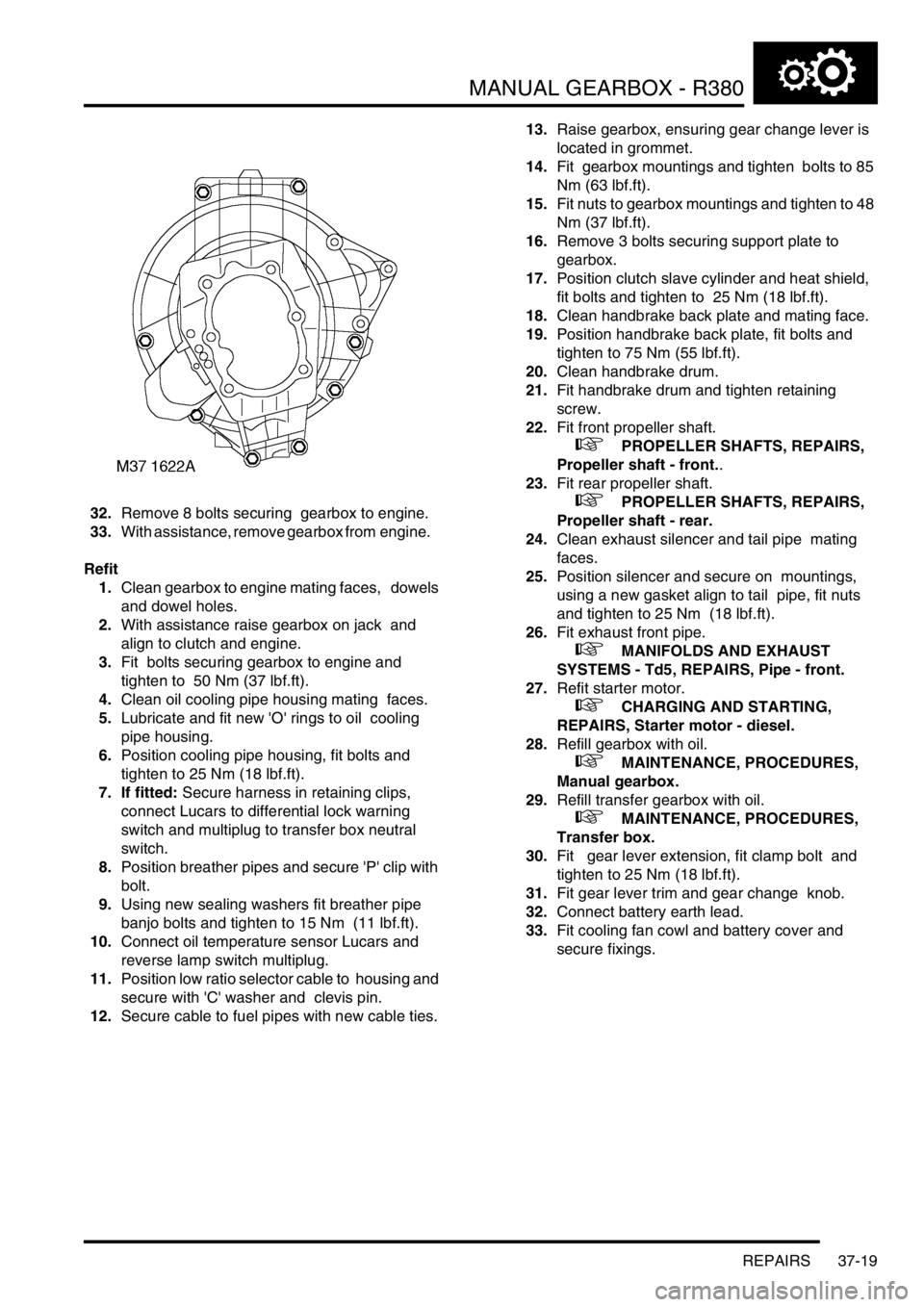
32.Remove 8 bolts securing gearbox to engine.
33.With assistance, remove gearbox from engine.
Refit
1.Clean gearbox to engine mating faces, dowels
and dowel holes.
2.With assistance raise gearbox on jack and
align to clutch and engine.
3.Fit bolts securing gearbox to engine and
tighten to 50 Nm (37 lbf.ft).
4.Clean oil cooling pipe housing mating faces.
5.Lubricate and fit new 'O' rings to oil cooling
pipe housing.
6.Position cooling pipe housing, fit bolts and
tighten to 25 Nm (18 lbf.ft).
7. If fitted: Secure harness in retaining clips,
connect Lucars to differential lock warning
switch and multiplug to transfer box neutral
switch.
8.Position breather pipes and secure 'P' clip with
bolt.
9.Using new sealing washers fit breather pipe
banjo bolts and tighten to 15 Nm (11 lbf.ft).
10.Connect oil temperature sensor Lucars and
reverse lamp switch multiplug.
11.Position low ratio selector cable to housing and
secure with 'C' washer and clevis pin.
12.Secure cable to fuel pipes with new cable ties. 13.Raise gearbox, ensuring gear change lever is
located in grommet.
14.Fit gearbox mountings and tighten bolts to 85
Nm (63 lbf.ft).
15.Fit nuts to gearbox mountings and tighten to 48
Nm (37 lbf.ft).
16.Remove 3 bolts securing support plate to
gearbox.
17.Position clutch slave cylinder and heat shield,
fit bolts and tighten to 25 Nm (18 lbf.ft).
18.Clean handbrake back plate and mating face.
19.Position handbrake back plate, fit bolts and
tighten to 75 Nm (55 lbf.ft).
20.Clean handbrake drum.
21.Fit handbrake drum and tighten retaining
screw.
22.Fit front propeller shaft.
+ PROPELLER SHAFTS, REPAIRS,
Propeller shaft - front..
23.Fit rear propeller shaft.
+ PROPELLER SHAFTS, REPAIRS,
Propeller shaft - rear.
24.Clean exhaust silencer and tail pipe mating
faces.
25.Position silencer and secure on mountings,
using a new gasket align to tail pipe, fit nuts
and tighten to 25 Nm (18 lbf.ft).
26.Fit exhaust front pipe.
+ MANIFOLDS AND EXHAUST
SYSTEMS - Td5, REPAIRS, Pipe - front.
27.Refit starter motor.
+ CHARGING AND STARTING,
REPAIRS, Starter motor - diesel.
28.Refill gearbox with oil.
+ MAINTENANCE, PROCEDURES,
Manual gearbox.
29.Refill transfer gearbox with oil.
+ MAINTENANCE, PROCEDURES,
Transfer box.
30.Fit gear lever extension, fit clamp bolt and
tighten to 25 Nm (18 lbf.ft).
31.Fit gear lever trim and gear change knob.
32.Connect battery earth lead.
33.Fit cooling fan cowl and battery cover and
secure fixings.
Page 823 of 1672

AUTOMATIC GEARBOX - ZF4HP22 - 24
44-26 REPAIRS
Refit
1.Clean shaft and seal housing.
2.Using a suitable adapter, fit new seal.
3.Position selector quadrant and connecting rod.
4.Position selector shaft and secure to quadrant
using new roll pin.
5.Fit valve body assembly.
+ AUTOMATIC GEARBOX - ZF4HP22
- 24, REPAIRS, Valve body assembly.
Gearbox - convertor and transfer
gearbox - Diesel
$% 44.20.04.99
Remove
1.Release fixings and remove battery cover.
2.Disconnect battery earth lead.
3.Raise vehicle on a ramp.
4.Remove starter motor
+ CHARGING AND STARTING,
REPAIRS, Starter motor - diesel.
5.Remove 2 upper bolts securing gearbox
housing to engine.
6.Remove bolt securing closing plate to gearbox
housing.
7.Remove exhaust front pipe.
+ MANIFOLDS AND EXHAUST
SYSTEMS - Td5, REPAIRS, Pipe - front.
8.Remove 3 nuts securing intermediate silencer
to tail pipe.
9.Release and remove silencer from rubber
mountings.
10.Drain automatic gearbox oil.
+ MAINTENANCE, PROCEDURES,
Automatic gearbox.
Page 827 of 1672

AUTOMATIC GEARBOX - ZF4HP22 - 24
44-30 REPAIRS
14.Secure gearbox breather pipes to bulkhead
clip.
15.Connect multiplugs to high/low ratio switch and
neutral sensor. Connect Lucars to differential
lock switch.
16.Position cable tie and multi plug to transfer box
bracket.
17.Connect high/low ratio cable to transfer box
and secure with retaining clips.
18.Position hand brake back plate and tighten
bolts to 75 Nm (55 lbf.ft).
19.Fit hand brake drum and tighten screw.
20.Remove bolts securing tool LRT-99-008A to
gearbox.
21.Rotate engine to align torque converter, fit new
bolts and tighten to 50 Nm (37 lbf.ft).
22.Fit rear propeller shaft.
+ PROPELLER SHAFTS, REPAIRS,
Propeller shaft - rear.
23.Fit front propeller shaft.
+ PROPELLER SHAFTS, REPAIRS,
Propeller shaft - front.
24.Fill transfer gearbox with oil.
+ MAINTENANCE, PROCEDURES,
Transfer box.
25.Fill automatic gearbox with oil.
+ MAINTENANCE, PROCEDURES,
Automatic gearbox.
26.Position intermediate silencer and secure to
mounting rubbers.
27.Clean silencer and tail pipe mating faces.
28.Position new gasket to tail pipe and tighten
nuts to 25 Nm (18 lbf.ft).
29.Fit exhaust front pipe.
+ MANIFOLDS AND EXHAUST
SYSTEMS - Td5, REPAIRS, Pipe - front.
30.Fit bolt securing closing plate to gearbox
housing and tighten to 7 Nm (5.2 lbf.ft).
31.Fit upper bolts securing gearbox housing to
engine and tighten to 50 Nm (37 lbf.ft).
32.Fit starter motor.
+ CHARGING AND STARTING,
REPAIRS, Starter motor - diesel.
33.Tighten remaining gearbox housing to engine
bolts to 50 Nm (37 lbf.ft).
34.Connect battery earth lead.
35.Fit battery cover and secure with fixings.
36.Check and adjust selector cable.
+ AUTOMATIC GEARBOX - ZF4HP22
- 24, ADJUSTMENTS, Cable - selector.
Gearbox - convertor and transfer
gearbox - V8
$% 44.20.04.99
Remove
1.Release fixings and remove battery cover.
2.Disconnect battery earth lead.
3.Raise vehicle on a ramp.
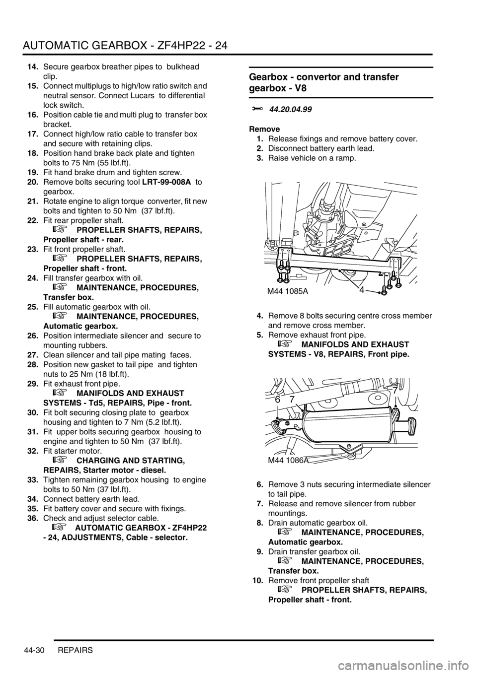
4.Remove 8 bolts securing centre cross member
and remove cross member.
5.Remove exhaust front pipe.
+ MANIFOLDS AND EXHAUST
SYSTEMS - V8, REPAIRS, Front pipe.
6.Remove 3 nuts securing intermediate silencer
to tail pipe.
7.Release and remove silencer from rubber
mountings.
8.Drain automatic gearbox oil.
+ MAINTENANCE, PROCEDURES,
Automatic gearbox.
9.Drain transfer gearbox oil.
+ MAINTENANCE, PROCEDURES,
Transfer box.
10.Remove front propeller shaft
+ PROPELLER SHAFTS, REPAIRS,
Propeller shaft - front.
Page 926 of 1672

STEERING
REPAIRS 57-39
Refit
1.Clean seal recess, output shaft, end cover and
mating face.
2.Lubricate new end cover 'O' ring with clean
PAS fluid. Fit 'O' ring to end cover.
3.Position output shaft, fit bolts and tighten to 88
Nm (65 lbf.ft).
4.Tighten rack adjuster one turn, align marks and
secure with Allen screw.
5.Lubricate new output shaft seal with clean PAS
fluid.
6.Fit seal using LRT-57-504.
7.Fit spacer, circlip and seal shield.
8.Clean drop arm and steering box splines.
9.Ensure steering box is in the central position.
Align and fit drop arm to output shaft and
secure with new lock washer and nut. Tighten
nut to 240 Nm (177 lbf.ft).
10.Secure lock washer to drop arm nut.
11.Fit steering box.
lFor V8 models:
+ STEERING, REPAIRS, Power
steering box - V8.
lFor LHD diesel models:
+ STEERING, REPAIRS, Power
steering box - LHD - diesel.
lFor RHD diesel models:
+ STEERING, REPAIRS, Steering
box - RHD - diesel.
Pump - power steering - V8
$% 57.20.14
Remove
1.Remove auxiliary drive belt.
+ CHARGING AND STARTING,
REPAIRS, Belt - auxiliary drive.
2.Remove cable tie securing harness to air intake
hose.
3.Loosen 3 clips securing air intake hose, release
and remove hose.
Note: Pre 03 MY air intake hose illustrated.
4. Models with ACE: Remove 3 bolts securing
ACE pump, release pump and position aside.
Page 928 of 1672

STEERING
REPAIRS 57-41
Refit
1.Position PAS pump to auxiliary housing and
locate housing to engine. Fit and tighten
auxiliary housing bolts to 40 Nm (30 lbf.ft).
2.Tighten auxiliary housing nut to 10 Nm (7 lbf.ft).
3.Fit bolts securing PAS pump and tighten to 22
Nm (16 lbf.ft).
4.Position PAS pump pipe bracket, fit and tighten
bolt to 22 Nm (16 lbf.ft).
5.Fit and tighten PAS pump pressure pipe.
6.Fit PAS pump inlet hose and secure with clip.
7.Position jockey pulley and tighten bolt to 50 Nm
(37 lbf.ft).
8.Clean PAS pump pulley mating faces.
9.Position PAS pump pulley, fit bolts and tighten
to 22 Nm (16 lbf.ft).
10. Models with ACE: Clean ACE pump dowels
and dowel holes. Position ACE pump, fit bolts
and tighten to 25 Nm (18 lbf.ft).
11. Models with A/C: Clean A/C compressor
dowels and dowel holes. Position A/C
compressor, fit bolts and tighten to 22 Nm (16
lbf.ft).
12.Position air intake hose and secure with clips.
13.Secure harness to air intake hose with new
cable tie.
14.Fit auxiliary drive belt.
+ CHARGING AND STARTING,
REPAIRS, Belt - auxiliary drive..
15.Bleed PAS system.
+ STEERING, ADJUSTMENTS,
Hydraulic system - bleed.
Pump - power steering - diesel
$% 57.20.14
Remove
1.Remove auxiliary drive belt.
+ CHARGING AND STARTING,
REPAIRS, Belt - auxiliary drive.
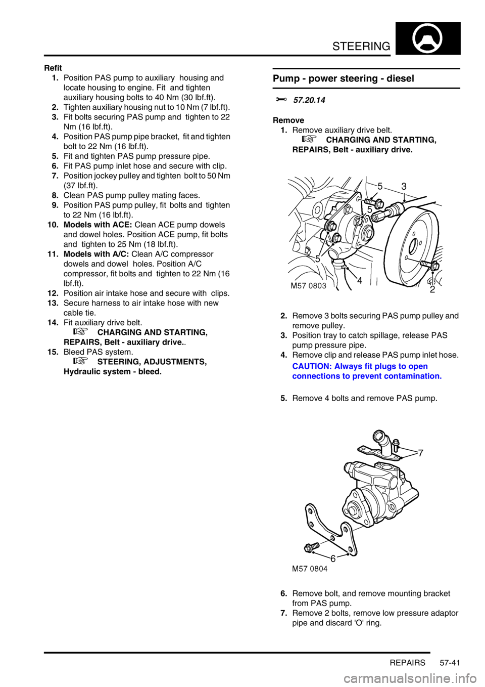
2.Remove 3 bolts securing PAS pump pulley and
remove pulley.
3.Position tray to catch spillage, release PAS
pump pressure pipe.
4.Remove clip and release PAS pump inlet hose.
CAUTION: Always fit plugs to open
connections to prevent contamination.
5.Remove 4 bolts and remove PAS pump.
6.Remove bolt, and remove mounting bracket
from PAS pump.
7.Remove 2 bolts, remove low pressure adaptor
pipe and discard 'O' ring.
Page 929 of 1672

STEERING
57-42 REPAIRS
Refit
1.Clean PAS pump and adaptor pipe.
2.Fit new 'O' ring to adaptor pipe, fit pipe and
tighten bolts to 10 Nm (7 lbf.ft).
3.Position mounting bracket to PAS pump, fit but
do not tighten bolt.
4.Position PAS pump and align pump drive to
coolant pump. Fit and tighten bolts to 25 Nm
(18 lbf.ft).
5.Tighten mounting plate bolt to 25 Nm (18 lbf.ft).
6.Clean PAS pump and pipe union.
7.Fit and tighten PAS pump pressure pipe to 20
Nm (15 lbf.ft).
8.Fit PAS pump inlet hose and secure with clip.
9.Clean PAS pump and pulley mating faces.
10.Position PAS pump pulley, fit and tighten bolts
to 10 Nm (7 lbf.ft).
11.Fit auxiliary drive belt.
+ CHARGING AND STARTING,
REPAIRS, Belt - auxiliary drive.
12.Bleed power steering system.
+ STEERING, ADJUSTMENTS,
Hydraulic system - bleed.
Steering column assembly and lock
$% 57.40.01
Remove
1.Remove steering column intermediate shaft.
+ STEERING, REPAIRS, Shaft -
intermediate and universal joint - steering
column.
2.Remove rotary coupler.
+ RESTRAINT SYSTEMS, REPAIRS,
Rotary coupler.
3.Open fascia lower access panel.
4.Remove steering column nacelle.
+ STEERING, REPAIRS, Nacelle -
steering column.
5.Disconnect multiplug and illumination bulb
from passive coil and remove passive coil.
Page 981 of 1672

FRONT SUSPENSION
60-42 REPAIRS
Accelerometer - ACE - lower
$% 60.60.03
CAUTION: The accelerometer is an extremely
delicate component and can easily be rendered
unserviceable. Never use an accelerometer
which has been dropped or subjected to
mistreatment of any type.
Remove
1.Raise vehicle on a ramp.
2.Disconnect multiplug from accelerometer.
3.Use LRT-60-014A to release clip and remove
accelerometer.
Refit
1.Use LRT-60-014A, fit accelerometer fully into
clip.
2.Connect accelerometer multiplug.
3.Lower vehicle.
4.If a replacement accelerometer has been fitted,
use TestBook to calibrate ACE system.
Pump - ACE - V8
$% 60.60.10
CAUTION: The ACE hydraulic system is
extremely sensitive to the ingress of dirt or
debris. The smallest amount could render the
system unserviceable. It is imperative that the
following precautions are taken.
lACE components are thoroughly cleaned
externally before work commences;
lall opened pipe and module ports are
capped immediately;
lall fluid is stored in and administered
through clean containers.
Remove
1.Remove auxiliary drive belt.
+ CHARGING AND STARTING,
REPAIRS, Belt - auxiliary drive.
2.Loosen 3 clips securing air intake hose.
Release air intake hose and position aside.
Note: Pre 03 MY air intake hose illustrated.