length LAND ROVER DISCOVERY 2002 Owner's Manual
[x] Cancel search | Manufacturer: LAND ROVER, Model Year: 2002, Model line: DISCOVERY, Model: LAND ROVER DISCOVERY 2002Pages: 1672, PDF Size: 46.1 MB
Page 774 of 1672
TRANSFER BOX - LT230SE
OVERHAUL 41-41
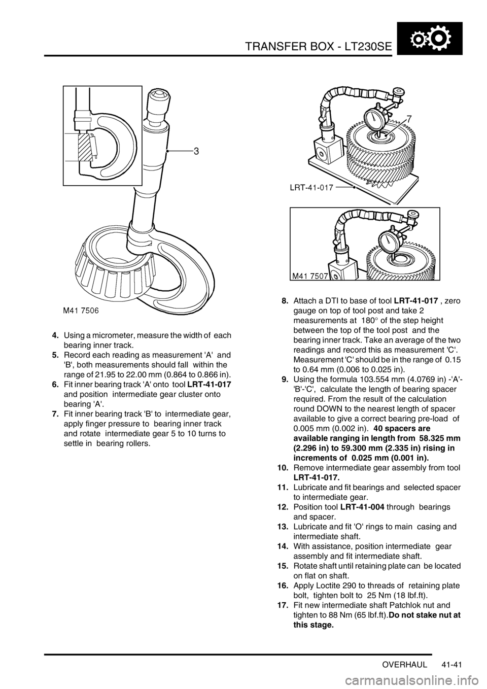
4.Using a micrometer, measure the width of each
bearing inner track.
5.Record each reading as measurement 'A' and
'B', both measurements should fall within the
range of 21.95 to 22.00 mm (0.864 to 0.866 in).
6.Fit inner bearing track 'A' onto tool LRT-41-017
and position intermediate gear cluster onto
bearing 'A'.
7.Fit inner bearing track 'B' to intermediate gear,
apply finger pressure to bearing inner track
and rotate intermediate gear 5 to 10 turns to
settle in bearing rollers. 8.Attach a DTI to base of tool LRT-41-017 , zero
gauge on top of tool post and take 2
measurements at 180
° of the step height
between the top of the tool post and the
bearing inner track. Take an average of the two
readings and record this as measurement 'C'.
Measurement 'C' should be in the range of 0.15
to 0.64 mm (0.006 to 0.025 in).
9.Using the formula 103.554 mm (4.0769 in) -'A'-
'B'-'C', calculate the length of bearing spacer
required. From the result of the calculation
round DOWN to the nearest length of spacer
available to give a correct bearing pre-load of
0.005 mm (0.002 in). 40 spacers are
available ranging in length from 58.325 mm
(2.296 in) to 59.300 mm (2.335 in) rising in
increments of 0.025 mm (0.001 in).
10.Remove intermediate gear assembly from tool
LRT-41-017.
11.Lubricate and fit bearings and selected spacer
to intermediate gear.
12.Position tool LRT-41-004 through bearings
and spacer.
13.Lubricate and fit 'O' rings to main casing and
intermediate shaft.
14.With assistance, position intermediate gear
assembly and fit intermediate shaft.
15.Rotate shaft until retaining plate can be located
on flat on shaft.
16.Apply Loctite 290 to threads of retaining plate
bolt, tighten bolt to 25 Nm (18 lbf.ft).
17.Fit new intermediate shaft Patchlok nut and
tighten to 88 Nm (65 lbf.ft).Do not stake nut at
this stage.
Page 781 of 1672

TRANSFER BOX - LT230SE
41-48 OVERHAUL
11.Check differential lock selector fork for cracks
and wear.
12.Check selector fork finger width.
lFinger width = 7.92 to 7.97 mm (0.311 to
0.313 in).
13.Check differential lock selector fork clips for
wear and damage. Check spring for distortion
and free length.
lSpring free length = 84.58 mm (3.33 in).
14.Check dog clutch internal teeth and grooves
and teeth on output shaft for wear and
damage. Check selector fork groove width.
lGroove width = 8.05 to 8.20 mm (0.32 to
0.33 in).
15.Carry out the following inspection procedures
for all transfer boxes.
16.Check threads and splines of output shaft for
damage and wear. Check dog clutch teeth on
shaft for wear and damage.17.03 MY onwards: Compress high/low selector
fork spring and remove retaining clips from
each end of spring, remove high/low selector
shaft.
18.Check detent grooves in high/low selector shaft
for wear. Do not remove fork from shaft
unless either component is being renewed.
If fork is removed from shaft, coat the
threads of the set screw with Loctite 290
prior to assembling.
Note: High/low selector shaft fitted to pre 03 MY
illustrated.
Page 782 of 1672

TRANSFER BOX - LT230SE
OVERHAUL 41-49
19.Check width of high/low selector groove.
lGroove width = 16.0 to 16.1 mm (0.63 to
0.64 in).
20.Check high/low selector fork for cracks and
wear. Check selector fork finger width.
lFinger width = 7.37 to 7.47 mm (0.290 to
0.294 in).
21.03 MY onwards: Check high/low selector fork
clips for wear and damage. Check spring for
distortion, check free length of spring:
lSpring free length = 75 mm (2.95 in)
Note: High/low selector shaft, fork and spring
fitted to 03 MY transfer boxes may be fitted to
pre 03 MY boxes as an assembly.
22.Check differential sun and planet gears for
wear, cracks and chipping of teeth.
23.Check cross shafts and recesses in both halves
of differential carrier for damage and
wear.Ensure planet gears are retained with
their respective shafts.
24.Check retaining ring for distortion.
25.Check differential splines for wear and
damage.26.Check high/low hub for cracks, chipping and
uneven wear. Check width of selector fork
groove.
lGroove width = 7.5 to 7.6 mm (0.295 to 0.30
in).
27.Check splines and teeth on high/low selector
sleeve for uneven wear, cracks, damage and
chipping.
28.Check teeth of high and low range gears for
cracks, chipping and uneven wear.
29.Check high range gear bush for wear and
damage.
Reassembly
1.Lubricate all components with recommended
oil and lightly oil the differential bolt threads.
Page 783 of 1672

TRANSFER BOX - LT230SE
41-50 OVERHAUL
2.Secure rear half of differential carrier in a soft
jawed vice.
3.Fit each planet gear to its respective cross
shaft, fit new dished thrust washer to each
gear.
4.Fit cross shafts, planet gears and dished thrust
washers in rear half of carrier.Ensure that
cross shafts are fitted correctly. Do not fit
the sun gear into the rear half carrier at this
stage.
5.Fit retaining ring.
6.Fit a 1.05 mm (0.04 in) thrust washer to sun
gear from front half of carrier. Position gear in
front half of carrier.
7.Ensuring that assembly marks are aligned, fit
both halves of carrier together.
8.Fit the differential carrier bolts and, working in a
diagonal sequence, tighten the bolts to 60 Nm,
(44 lbf.ft).9.Insert the front output shaft into the front half of
the carrier and check that the gears rotate
freely.
10.Fit output flange on to the splines of the output
shaft, but do not fit flange nut at this stage.
11.Fit transmission brake drum to output flange
and secure the drum using 2 nuts.
12.Secure a length of cord around the drum and
attach one end of the cord to a spring balance.
13.Pull on the spring balance and note the load at
which the brake drum starts to turn. Used
gears should rotate smoothly, while new
gears will have a 'notchy' feel as they rotate.
14.Compare the figure obtained with the following.
lUsed gears = 0.45 kg (1.0 lb)
lNew gears = 1.72 kg (3.8 lb)
15.If the load to turn figure is below the specified
limits, proceed as follows.
16.Remove the front output shaft and brake drum.
17.Remove the 8 bolts securing the two halves of
the differential carrier
18.Separate the differential carrier and remove the
sun gear and thrust washer from the front half.
19.Select a thicker thrust washer from the range
available. 5 different thrust washers are
available, rising in increments of 0.10 mm
(0.004 in) from 1.05 mm to 1.45 mm (0.04 to
0.06 in).
20.Repeat steps 7 to 19 as necessary until the
load to turn figure is as specified
21.When specified load to turn is obtained,
proceed as follows.
22.Remove the front output shaft and brake drum.
23.Remove the 8 bolts securing the two halves of
the differential carrier
24.Separate the differential carrier and remove the
sun gear and thrust washer from the front
half.Retain the selected thrust washer with
its sun gear.
Page 853 of 1672
PROPELLER SHAFTS
47-2 DESCRIPTION AND OPERATION
Description
General
Front and rear propeller shafts transmit the drive from the transfer box to the axles.
On vehicles from 03 model year fitted with the 4.6l V8 engine and 4HP24 transmission, the front propeller shaft is 15
mm (0.6 in) longer and the rear propeller shaft is 15mm (0.6 in) shorter than those used on vehicles with the 4.0l V8
and Td5 engines. This is to accomodate an increase in length of the 4HP24 transmission.
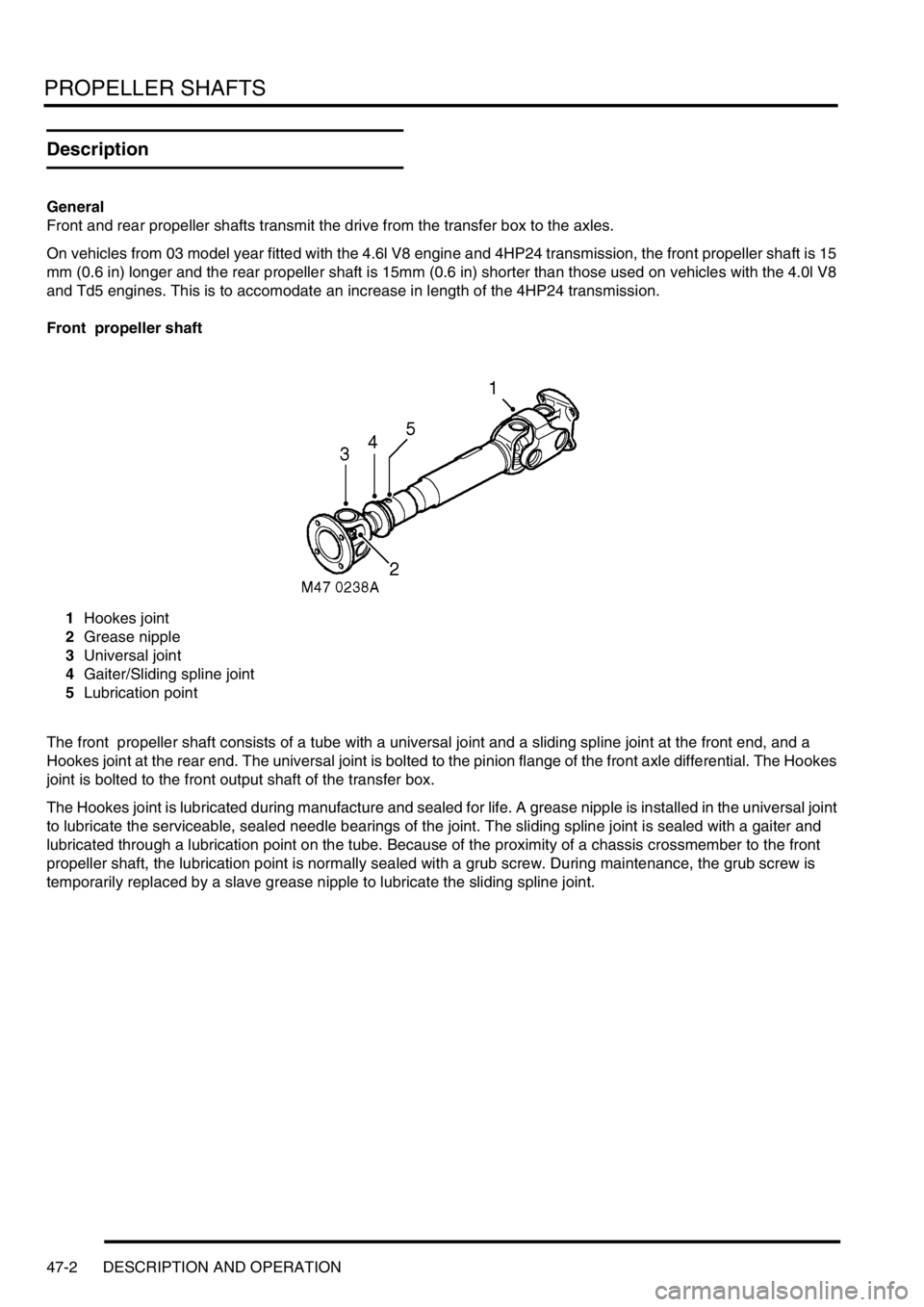
Front propeller shaft
1Hookes joint
2Grease nipple
3Universal joint
4Gaiter/Sliding spline joint
5Lubrication point
The front propeller shaft consists of a tube with a universal joint and a sliding spline joint at the front end, and a
Hookes joint at the rear end. The universal joint is bolted to the pinion flange of the front axle differential. The Hookes
joint is bolted to the front output shaft of the transfer box.
The Hookes joint is lubricated during manufacture and sealed for life. A grease nipple is installed in the universal joint
to lubricate the serviceable, sealed needle bearings of the joint. The sliding spline joint is sealed with a gaiter and
lubricated through a lubrication point on the tube. Because of the proximity of a chassis crossmember to the front
propeller shaft, the lubrication point is normally sealed with a grub screw. During maintenance, the grub screw is
temporarily replaced by a slave grease nipple to lubricate the sliding spline joint.
Page 892 of 1672
STEERING
DESCRIPTION AND OPERATION 57-5
Description
General
The major steering components comprise an impact absorbing telescopic steering column, a Power Assisted Steering
(PAS) box, a PAS pump, and fluid reservoir. Hydraulic fluid from the fluid reservoir is filtered and then supplied
through the suction line to the inlet on the PAS pump. The PAS pump supplies fluid to the steering box through a
pressure line routed above the front cross member. Fluid returns to the reservoir along the same route through a
return line. On LH drive vehicles the pipe route above the front cross member is still used, the length of pipe acting
as an oil cooler.
To minimise driver's injury in the event of an accident the steering system has a number of safety features including
a collapsible steering column. An additional safety feature is an air bag located in the steering wheel.
+ RESTRAINT SYSTEMS, DESCRIPTION AND OPERATION, Description - SRS.
Steering column assembly and intermediate shaft
The steering column central shaft comprises of two shafts, the upper shaft is splined to accept the steering wheel and
located in bearings in the column tube. A universal joint is located on the bottom of the upper shaft, the joint allows
for angular movement between the upper and lower shafts. The lower shaft is made in two parts, the top section of
the lower shaft is located outside of the lower section. The two sections of the lower shaft are connected by two nylon
injection moulded shear pins. The lower shaft goes through a lower bearing attached to the bulkhead, the lower shaft
is connected by a universal joint to the intermediate shaft in the engine compartment.
Steering column
An upper column tube provides for the location of the steering lock and ignition switch and also the steering switch
gear and a rotary coupler. The rotary coupler provides the electrical connection for the steering wheel mounted airbag,
switches and horn. The upper mounting bracket has two slots, a slotted metal bracket is held in each slot by four resin
shear pins.
The column is mounted on four captive studs which are located on a column mounting bracket. The captive studs
pass through the metal brackets, locknuts secure the steering column to the bulkhead. The two lower mountings are
fixed and cannot move when loads are applied to them. The upper mounting is designed to disengage or deform when
a load is applied, allowing the column to collapse in the event of an accident. The steering column must be replaced
as a complete assembly if necessary.
When an axial load is applied to the upper column tube, energy absorption is achieved by the following mechanism:
lthe mounting bracket deforms,
lthe resin shear pins holding the slotted metal brackets shear,
lthe top mounting bracket slides out of the slotted metal brackets.
The slotted metal brackets remain on the captive studs on the bulkhead. If the column mounting moves, injection
moulded shear pins retaining the two sections of the lower column shaft will shear. This allows the two sections of the
lower shaft to 'telescope' together.
In the event of a collision where the steering box itself moves, two universal joints in the column allow the intermediate
shaft to articulate, minimising movement of the column towards the driver. If movement continues energy absorption
is achieved by the following mechanism:
lthe decouple joint in the intermediate shaft will disengage,
lthe lower section of the steering column shaft will move through the lower bearing,
lthe injection moulded shear pins retaining the two sections of the lower column shaft will shear.
This allows the two sections of the lower shaft to 'telescope' together reducing further column intrusion. Protection to
the drivers face and upper torso is provided by an SRS airbag module located in the centre of the steering wheel.
+ RESTRAINT SYSTEMS, DESCRIPTION AND OPERATION, Description - SRS.
Page 906 of 1672

STEERING
ADJUSTMENTS 57-19
5.Adjust drag link so that taper joint is centralised
in drop arm, then tighten drag link clamp bolts:
Tighten M8 bolts to 22 Nm (16 lbf.ft) and M10
bolts to 33 Nm (24 lbf.ft).
6.Connect drag link to drop arm and tighten nut to
80 Nm (59 lbf.ft).
7.Remove steering box centralising bolt.
8.Remove stand(s) and lower vehicle.
9.Road test the vehicle and check that the
steering wheel is centralised. If steering wheel
is not centralised, proceed as follows.
10.Slacken drag link adjuster clamp bolts.
11.Without disconnecting drag link from drop arm,
adjust the length of the drag link to bring the
steering wheel to the central position.
CAUTION: Repositioning the steering wheel
on its splines cannot correct small (less
than 5
°) errors in steering wheel alignment.
Always rectify small errors in alignment by
adjusting the drag link as detailed above,
ensuring that steering box centralisation is
maintained.
12.Tighten drag link clamp bolts: Tighten M8 bolts
to 22 Nm (16 lbf.ft) and M10 bolts to 33 Nm (24
lbf.ft)
Wheel alignment - front
$% 57.65.01
The following is the only wheel alignment equipment
which has been approved.
lBeissbarth ML 4600 wheel alignment computer
(6 sensor).
lBeissbarth ML 4600-8 wheel alignment
computer (8 sensor).
lBeissbarth ML 4000 wheel alignment computer
(8 sensor wireless).
lHunter S411-14.
Check
1.Ensure tyre pressures are correct and vehicle
is at kerbside weight.
2.Roll vehicle backwards and forwards to relieve
stresses in steering and suspension.
3.Ensure road wheels are positioned straight
ahead.
4.Ensure that wheel alignment equipment is
properly calibrated.
5.Following the equipment manufacturer's
instructions, measure the front wheel
alignment. Compare with the figures given in
General Data.
+ GENERAL DATA, Steering.
Adjust
1.Loosen track rod and adjuster clamp bolts.
2.Rotate adjuster to obtain correct alignment.
+ GENERAL DATA, Steering.
3.Tighten track rod and adjuster clamp bolts:
Tighten M8 bolts to 22 Nm (16 lbf.ft) and M10
bolts to 33 Nm (24 lbf.ft).
4.Recheck front wheel alignment.
Page 935 of 1672
STEERING
57-48 REPAIRS
Ball joint - track rod
$% 57.55.07
Remove
1.Raise front of vehicle.
WARNING: Do not work on or under a
vehicle supported only by a jack. Always
support the vehicle on safety stands.
2.Remove LH front road wheel.
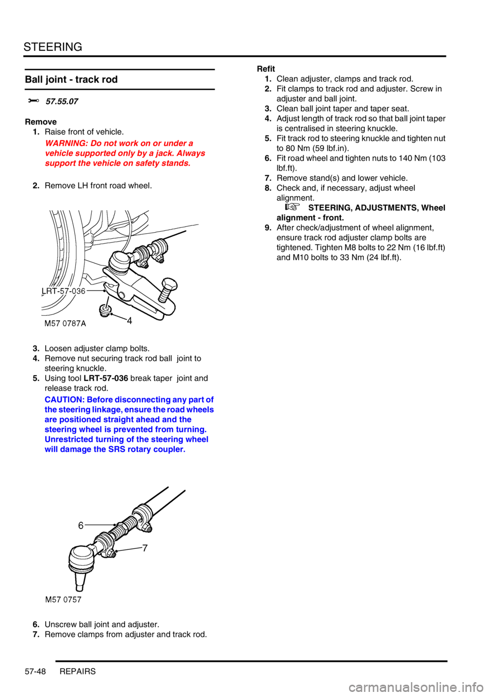
3.Loosen adjuster clamp bolts.
4.Remove nut securing track rod ball joint to
steering knuckle.
5.Using tool LRT-57-036 break taper joint and
release track rod.
CAUTION: Before disconnecting any part of
the steering linkage, ensure the road wheels
are positioned straight ahead and the
steering wheel is prevented from turning.
Unrestricted turning of the steering wheel
will damage the SRS rotary coupler.
6.Unscrew ball joint and adjuster.
7.Remove clamps from adjuster and track rod. Refit
1.Clean adjuster, clamps and track rod.
2.Fit clamps to track rod and adjuster. Screw in
adjuster and ball joint.
3.Clean ball joint taper and taper seat.
4.Adjust length of track rod so that ball joint taper
is centralised in steering knuckle.
5.Fit track rod to steering knuckle and tighten nut
to 80 Nm (59 lbf.in).
6.Fit road wheel and tighten nuts to 140 Nm (103
lbf.ft).
7.Remove stand(s) and lower vehicle.
8.Check and, if necessary, adjust wheel
alignment.
+ STEERING, ADJUSTMENTS, Wheel
alignment - front.
9.After check/adjustment of wheel alignment,
ensure track rod adjuster clamp bolts are
tightened. Tighten M8 bolts to 22 Nm (16 lbf.ft)
and M10 bolts to 33 Nm (24 lbf.ft).
Page 936 of 1672
STEERING
REPAIRS 57-49
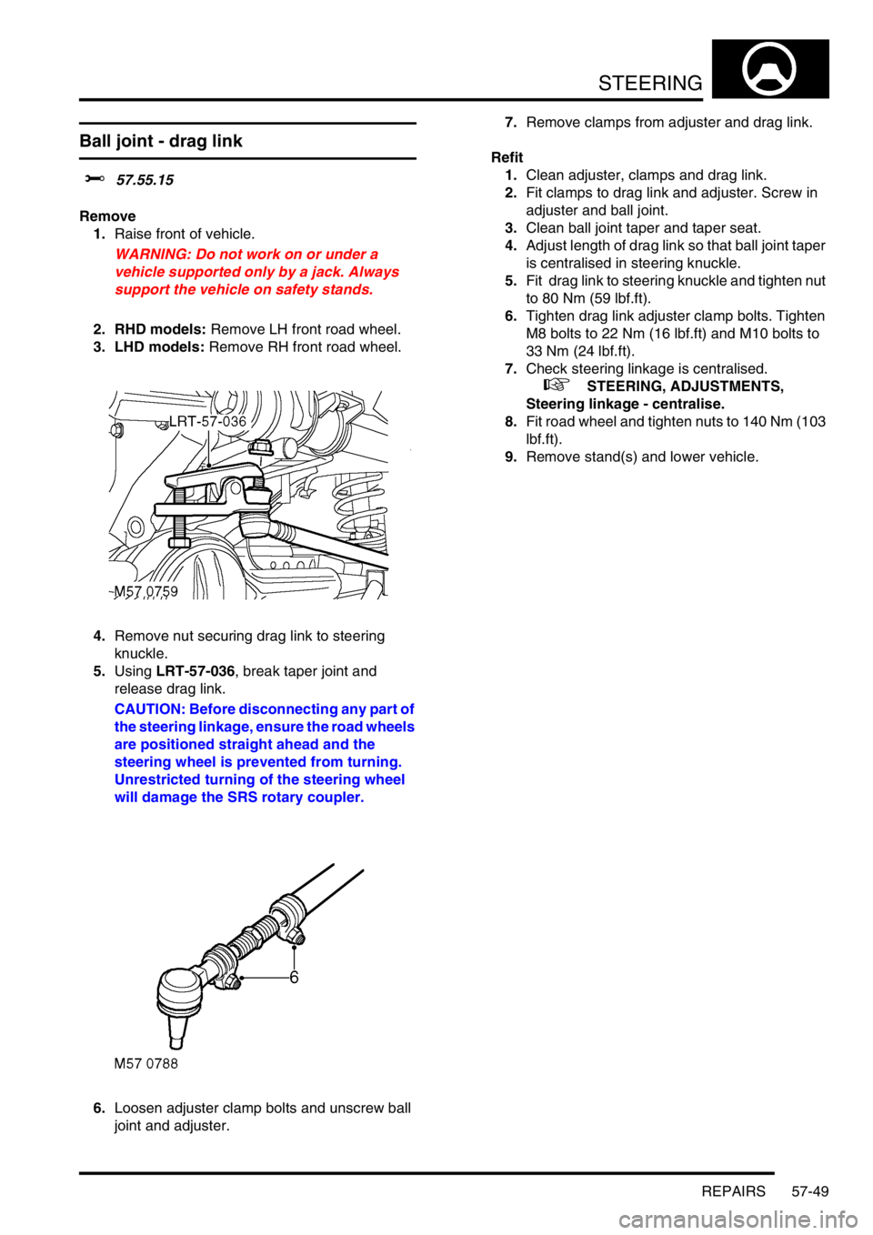
Ball joint - drag link
$% 57.55.15
Remove
1.Raise front of vehicle.
WARNING: Do not work on or under a
vehicle supported only by a jack. Always
support the vehicle on safety stands.
2. RHD models: Remove LH front road wheel.
3. LHD models: Remove RH front road wheel.
4.Remove nut securing drag link to steering
knuckle.
5.Using LRT-57-036, break taper joint and
release drag link.
CAUTION: Before disconnecting any part of
the steering linkage, ensure the road wheels
are positioned straight ahead and the
steering wheel is prevented from turning.
Unrestricted turning of the steering wheel
will damage the SRS rotary coupler.
6.Loosen adjuster clamp bolts and unscrew ball
joint and adjuster. 7.Remove clamps from adjuster and drag link.
Refit
1.Clean adjuster, clamps and drag link.
2.Fit clamps to drag link and adjuster. Screw in
adjuster and ball joint.
3.Clean ball joint taper and taper seat.
4.Adjust length of drag link so that ball joint taper
is centralised in steering knuckle.
5.Fit drag link to steering knuckle and tighten nut
to 80 Nm (59 lbf.ft).
6.Tighten drag link adjuster clamp bolts. Tighten
M8 bolts to 22 Nm (16 lbf.ft) and M10 bolts to
33 Nm (24 lbf.ft).
7.Check steering linkage is centralised.
+ STEERING, ADJUSTMENTS,
Steering linkage - centralise.
8.Fit road wheel and tighten nuts to 140 Nm (103
lbf.ft).
9.Remove stand(s) and lower vehicle.
Page 937 of 1672
STEERING
57-50 REPAIRS
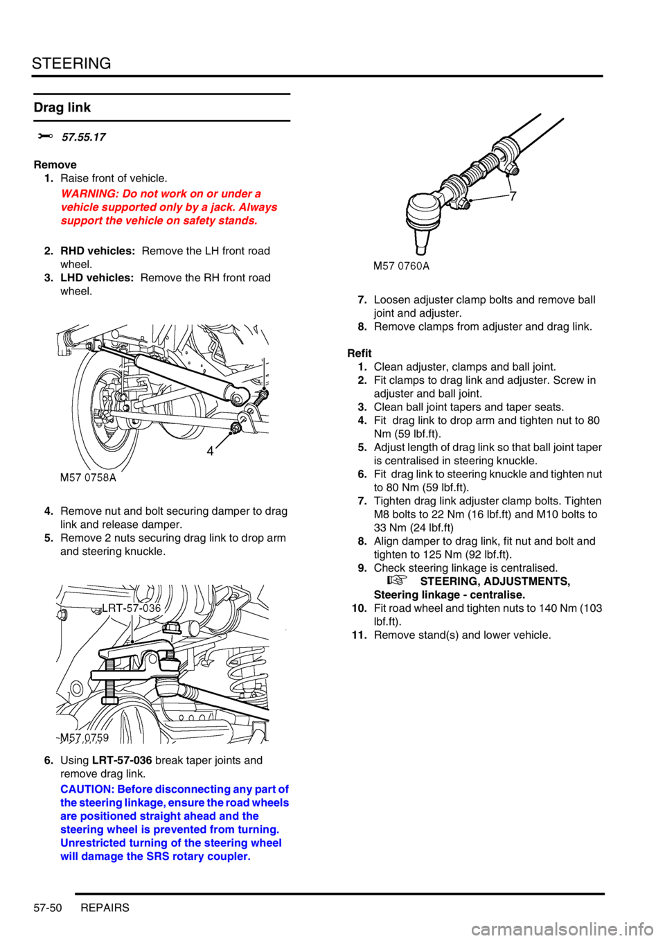
Drag link
$% 57.55.17
Remove
1.Raise front of vehicle.
WARNING: Do not work on or under a
vehicle supported only by a jack. Always
support the vehicle on safety stands.
2. RHD vehicles: Remove the LH front road
wheel.
3. LHD vehicles: Remove the RH front road
wheel.
4.Remove nut and bolt securing damper to drag
link and release damper.
5.Remove 2 nuts securing drag link to drop arm
and steering knuckle.
6.Using LRT-57-036 break taper joints and
remove drag link.
CAUTION: Before disconnecting any part of
the steering linkage, ensure the road wheels
are positioned straight ahead and the
steering wheel is prevented from turning.
Unrestricted turning of the steering wheel
will damage the SRS rotary coupler.7.Loosen adjuster clamp bolts and remove ball
joint and adjuster.
8.Remove clamps from adjuster and drag link.
Refit
1.Clean adjuster, clamps and ball joint.
2.Fit clamps to drag link and adjuster. Screw in
adjuster and ball joint.
3.Clean ball joint tapers and taper seats.
4.Fit drag link to drop arm and tighten nut to 80
Nm (59 lbf.ft).
5.Adjust length of drag link so that ball joint taper
is centralised in steering knuckle.
6.Fit drag link to steering knuckle and tighten nut
to 80 Nm (59 lbf.ft).
7.Tighten drag link adjuster clamp bolts. Tighten
M8 bolts to 22 Nm (16 lbf.ft) and M10 bolts to
33 Nm (24 lbf.ft)
8.Align damper to drag link, fit nut and bolt and
tighten to 125 Nm (92 lbf.ft).
9.Check steering linkage is centralised.
+ STEERING, ADJUSTMENTS,
Steering linkage - centralise.
10.Fit road wheel and tighten nuts to 140 Nm (103
lbf.ft).
11.Remove stand(s) and lower vehicle.