length LAND ROVER DISCOVERY 2002 Service Manual
[x] Cancel search | Manufacturer: LAND ROVER, Model Year: 2002, Model line: DISCOVERY, Model: LAND ROVER DISCOVERY 2002Pages: 1672, PDF Size: 46.1 MB
Page 1238 of 1672
CHASSIS AND BODY DIMENSIONS
BODY DIMENSIONS 77-1-5
BODY DIMENSIONS
Body Dimensions
The following dimensional information is shown to assist the technician in the diagnosis and repair of body panels.
The information is shown in two different forms. In the first part of the information X,Y and Z dimensions are shown
and in the second part actual point to point dimensions are shown.
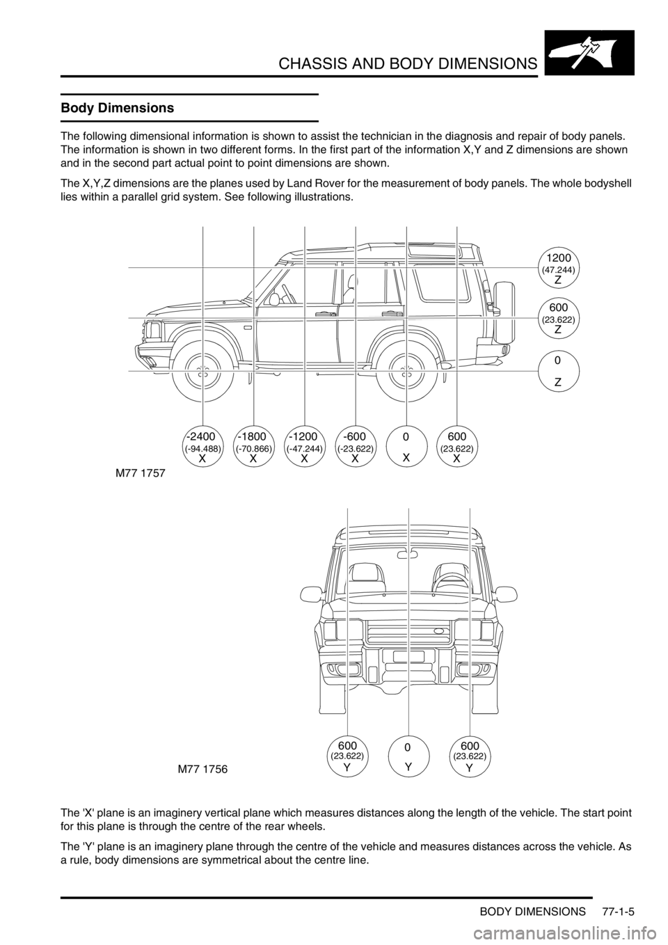
The X,Y,Z dimensions are the planes used by Land Rover for the measurement of body panels. The whole bodyshell
lies within a parallel grid system. See following illustrations.
The 'X' plane is an imaginery vertical plane which measures distances along the length of the vehicle. The start point
for this plane is through the centre of the rear wheels.
The 'Y' plane is an imaginery plane through the centre of the vehicle and measures distances across the vehicle. As
a rule, body dimensions are symmetrical about the centre line.
M77 1757
-2400
(-94.488)X
-1800
(-70.866)
-1200-6000600
(-47.244)(-23.622)(23.622)XXXXX
1200
(47.244)Z
600
(23.622)Z
0
Z
M77 1756
0
Y
600(23.622)
Y
600(23.622)
Y
Page 1242 of 1672
CHASSIS AND BODY DIMENSIONS
BODY DIMENSIONS 77-1-9
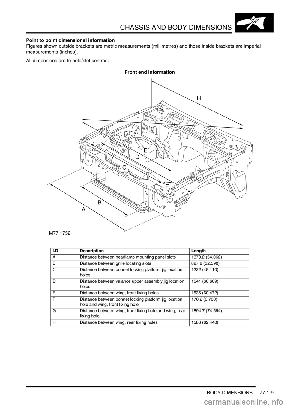
Point to point dimensional information
Figures shown outside brackets are metric measurements (millimetres) and those inside brackets are imperial
measurements (inches).
All dimensions are to hole/slot centres.
Front end information
I.D Description Length
A Distance between headlamp mounting panel slots 1373.2 (54.062)
B Distance between grille locating slots 827.8 (32.590)
C Distance between bonnet locking platform jig location
holes1222 (48.110)
D Distance between valance upper assembly jig location
holes1541 (60.669)
E Distance between wing, front fixing holes 1536 (60.472)
F Distance between bonnet locking platform jig location
hole and wing, front fixing hole170.2 (6.700)
G Distance between wing, front fixing hole and wing, rear
fixing hole1894.7 (74.594)
H Distance between wing, rear fixing holes 1586 (62.440)
M77 1752
A
B
C
D
E
F
G
H
Page 1243 of 1672
CHASSIS AND BODY DIMENSIONS
77-1-10 BODY DIMENSIONS
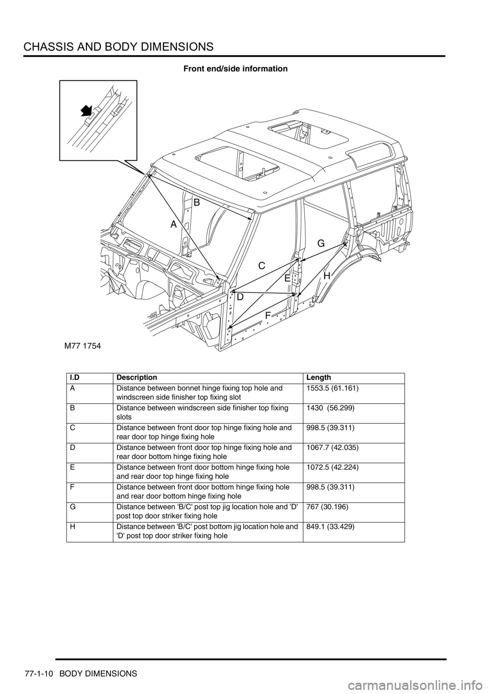
Front end/side information
I.D Description Length
A Distance between bonnet hinge fixing top hole and
windscreen side finisher top fixing slot1553.5 (61.161)
B Distance between windscreen side finisher top fixing
slots1430 (56.299)
C Distance between front door top hinge fixing hole and
rear door top hinge fixing hole998.5 (39.311)
D Distance between front door top hinge fixing hole and
rear door bottom hinge fixing hole1067.7 (42.035)
E Distance between front door bottom hinge fixing hole
and rear door top hinge fixing hole1072.5 (42.224)
F Distance between front door bottom hinge fixing hole
and rear door bottom hinge fixing hole998.5 (39.311)
G Distance between 'B/C' post top jig location hole and 'D'
post top door striker fixing hole767 (30.196)
H Distance between 'B/C' post bottom jig location hole and
'D' post top door striker fixing hole849.1 (33.429)
M77 1754
A
B
C
D
G
E
F
H
Page 1244 of 1672

CHASSIS AND BODY DIMENSIONS
BODY DIMENSIONS 77-1-11
Internal information
I.D Description Length
A Distance between seat belt anchorage top fixing and
seat belt reel lower fixing1814.5 (71.437)
B Distance between seat belt anchorage lower fixings on
wheel arch inner1430.2 (56.307)
M77 1760
A
B
Page 1245 of 1672

CHASSIS AND BODY DIMENSIONS
77-1-12 BODY DIMENSIONS
Rear end information
I.D Description Length
A Distance between taildoor setting block, jig location hole
and taildoor bottom hinge, middle fixing hole1364.4 (53.716)
B Distance between taildoor setting block, jig location hole
and taildoor top hinge, middle fixing hole1319.8 (51.960)
C Distance between crossmember outer rear panel, jig
location hole and rear headrest fixing hole 1413 (55.629)
M77 1758A
A
B
C
Page 1262 of 1672
PANEL REPAIRS
PROCEDURES 77-2-13
PROCEDURES
General welding precautions
General
For ease of reference, the diagrams on the following pages show only the type of weld used in repair where it varies
from that used in production.
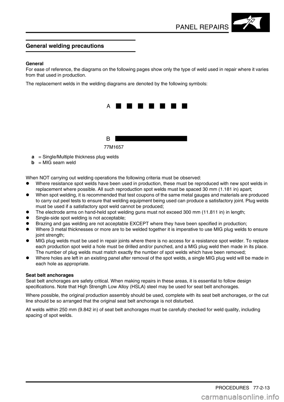
The replacement welds in the welding diagrams are denoted by the following symbols:
a = Single/Multiple thickness plug welds
b = MIG seam weld
When NOT carrying out welding operations the following criteria must be observed:
lWhere resistance spot welds have been used in production, these must be reproduced with new spot welds in
replacement where possible. All such reproduction spot welds must be spaced 30 mm (1.181 in) apart;
lWhen spot welding, it is recommended that test coupons of the same metal gauges and materials are produced
to carry out peel tests to ensure that welding equipment being used can produce a satisfactory joint. Plug welds
must be used if a satisfactory spot weld cannot be produced;
lThe electrode arms on hand-held spot welding guns must not exceed 300 mm (11.811 in) in length;
lSingle-side spot welding is not acceptable;
lBrazing and gas welding are not acceptable EXCEPT where they have been specified in production;
lWhere 3 metal thicknesses or more are to be welded together it is imperative to use MIG plug welds to ensure
joint strength;
lMIG plug welds must be used in repair joints where there is no access for a resistance spot welder. To replace
each production spot weld a hole must be drilled and/or punched, and a MIG plug weld then made in its place.
The number of plug welds must match exactly the number of spot welds which have been removed;
lWhere holes are left in an existing panel after removal of the spot welds, a single MIG plug weld will be made in
each hole as appropriate.
Seat belt anchorages
Seat belt anchorages are safety critical. When making repairs in these areas, it is essential to follow design
specifications. Note that High Strength Low Alloy (HSLA) steel may be used for seat belt anchorages.
Where possible, the original production assembly should be used, complete with its seat belt anchorages, or the cut
line should be so arranged that the original seat belt anchorage is not disturbed.
All welds within 250 mm (9.842 in) of seat belt anchorages must be carefully checked for weld quality, including
spacing of spot welds.
Page 1267 of 1672
PANEL REPAIRS
77-2-18 PROCEDURES
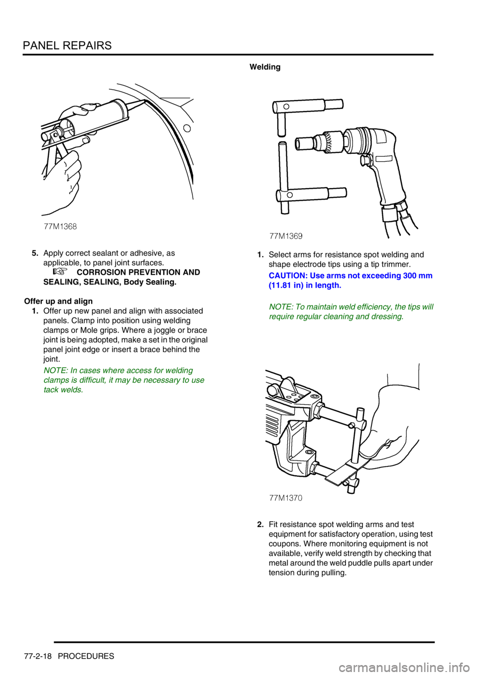
5.Apply correct sealant or adhesive, as
applicable, to panel joint surfaces.
+ CORROSION PREVENTION AND
SEALING, SEALING, Body Sealing.
Offer up and align
1.Offer up new panel and align with associated
panels. Clamp into position using welding
clamps or Mole grips. Where a joggle or brace
joint is being adopted, make a set in the original
panel joint edge or insert a brace behind the
joint.
NOTE: In cases where access for welding
clamps is difficult, it may be necessary to use
tack welds.Welding
1.Select arms for resistance spot welding and
shape electrode tips using a tip trimmer.
CAUTION: Use arms not exceeding 300 mm
(11.81 in) in length.
NOTE: To maintain weld efficiency, the tips will
require regular cleaning and dressing.
2.Fit resistance spot welding arms and test
equipment for satisfactory operation, using test
coupons. Where monitoring equipment is not
available, verify weld strength by checking that
metal around the weld puddle pulls apart under
tension during pulling.
Page 1312 of 1672
BODY SEALING MATERIALS
MATERIALS AND APPLICATIONS 77-3-5
Cooper Pegler Falcon Junior Pneumatic Gun (Airless)
Intended primarily for applying transit wax, this pneumatic sprayer has a 5-litre container with integral hand pump and
provides an effective means of wax spraying without the need for compressed air or additional services.
A selection of nozzles, lances, hose lengths and a trigger valve assembly with integral filter allows flexibility in use.
Additional applications include general maintenance, wax injection and paint application. Heavy-bodied materials
may also be applied. All parts are fully replaceable and a wide range of nozzle configurations is available.
SATA Schutz Gun Model UBE
The SATA Schutz Gun is approved for the retreatment of vehicle underbody areas with protective coatings as
supplied in 1 litre, purpose-designed 'one-way' containers. The screw thread fitting (female on the gun) is standard
to most Schutz-type packs.
SATA HKD1 Wax Injection Injection Equipment
This equipment is approved for carrying out cavity wax re-treatment. The SATA HKD1 set comprises a high quality
forged gun with 1-litre pressure feed container, a flexible nylon lance, a straight 1100 mm (43.307 in) steel lance and
hooked- wand lance. A quick-change coupling is provided as a standard fitting to allow lances to be easily
interchanged. Each lance has an integral, machined nozzle with specialised spray characteristics to suit the type of
box section to be treated.
NOTE: Always clean gun after use with appropriate solvent to maintain efficiency.
Specifications of Model UBE:
Air consumption 7 ft
3/min (200 litres/min) @ 45 lbf.in2
Weight: 23.3oz (220 grams)
Page 1429 of 1672

WIPERS AND WASHERS
84-8 DESCRIPTION AND OPERATION
Description
General
All markets have a common wiper system with headlamp powerwash as an option.
The wipers system comprises two front wipers and one rear wiper which are powered by electric motors. A washer
reservoir is located in the front left hand wheel arch and is fitted with two electric pumps. Each pump supplies washer
fluid to either the front or rear screens. On certain models, a third pump can be fitted to operate a headlamp power
wash function. Operation of the front and rear wipers and washers is controlled by the driver using switches located
on a steering column stalk and push button switches on the fascia.
Control of the wipers and washers is achieved by the following components:
lBCU.
lIDM.
lFront wiper relay.
lFront wash/ wipe switch.
lVariable delay switch.
lFront wiper motor assembly.
lFront washer pump motor.
lRear wiper relay.
lRear wiper switch.
lRear washer switch.
lRear wiper motor.
lRear washer pump motor.
Both the Body Control Unit (BCU) and the Intelligent Driver Module (IDM) control the wiper system. The BCU controls
the time delay function of the wiper system and is located below and behind the passenger glovebox. During engine
cranking the BCU prevents wiper functions. Two relays are located in the passenger compartment fusebox. The
relays control the delay operation of the front and rear wipers. The relays are an integral part of the fusebox and
cannot be renewed separately.
Power for the wiper system is supplied by the IDM, which is integral with the passenger fusebox and cannot be
renewed as a component. A serial communication link allows communication between the IDM and the BCU.
The system has diagnostic capabilities through TestBook.
Front wipers
The two front windscreen wipers are operated by a linkage assembly and an electric motor located under the plenum
grill below the windscreen. The linkage and motor assembly is handed for left and right hand drive vehicles. The motor
is an integral part of the linkage and cannot be replaced separately.
The linkage comprises a pressed steel mounting plate which provides for the attachment of a wheel box at each end.
The mounting plate is secured to the bulkhead with flanged nuts which attach to a stud plate located behind the
bulkhead. A link arm is attached to each wheel box by a short link and secured with circlips. The link arm has an
attachment hole centrally located along its length for the electric motor drive link.
The electric motor is mounted in a recess in the bulkhead below a sealed cover plate. The drive spindle of the motor
protrudes through the cover plate and is fitted with a link. The link is attached to a tapered spline on the motor spindle
and is secured with a lock washer and nut. The opposite end of the link is attached to the central attachment point on
the link arm and secured with a circlip.
Each wheel box has a taper splined shaft which allows for the attachment of the wiper arm which is secured with a
washer and nut. The shaft of each wheel box is passed through a rubber sealed aperture in the plenum. The wiper
arm attachment to the splined shaft has a pivot to which the remainder of the arm is attached. The two parts of the
arm are connected by a spring which controls the pressure of the blade on the screen to a predetermined amount.
Page 1430 of 1672
WIPERS AND WASHERS
DESCRIPTION AND OPERATION 84-9
The wiper blades are attached to the wiper arms with a clips that allow the blade to pivot. Each wiper blade comprises
a number of levers and yokes to which the rubber wiper is attached. The levers and yokes ensure that the pressure
applied by the arm spring is distributed evenly along the full length of the blade. The rubber wiper is held in the yokes
by a pair of stainless steel strips which also contribute to the even distribution of spring pressure along the blade. The
driver's side wiper blade is fitted with an aerofoil which presses the blade onto the screen at high speed. This prevents
the blade from lifting off the screen and maintains the wiping performance.
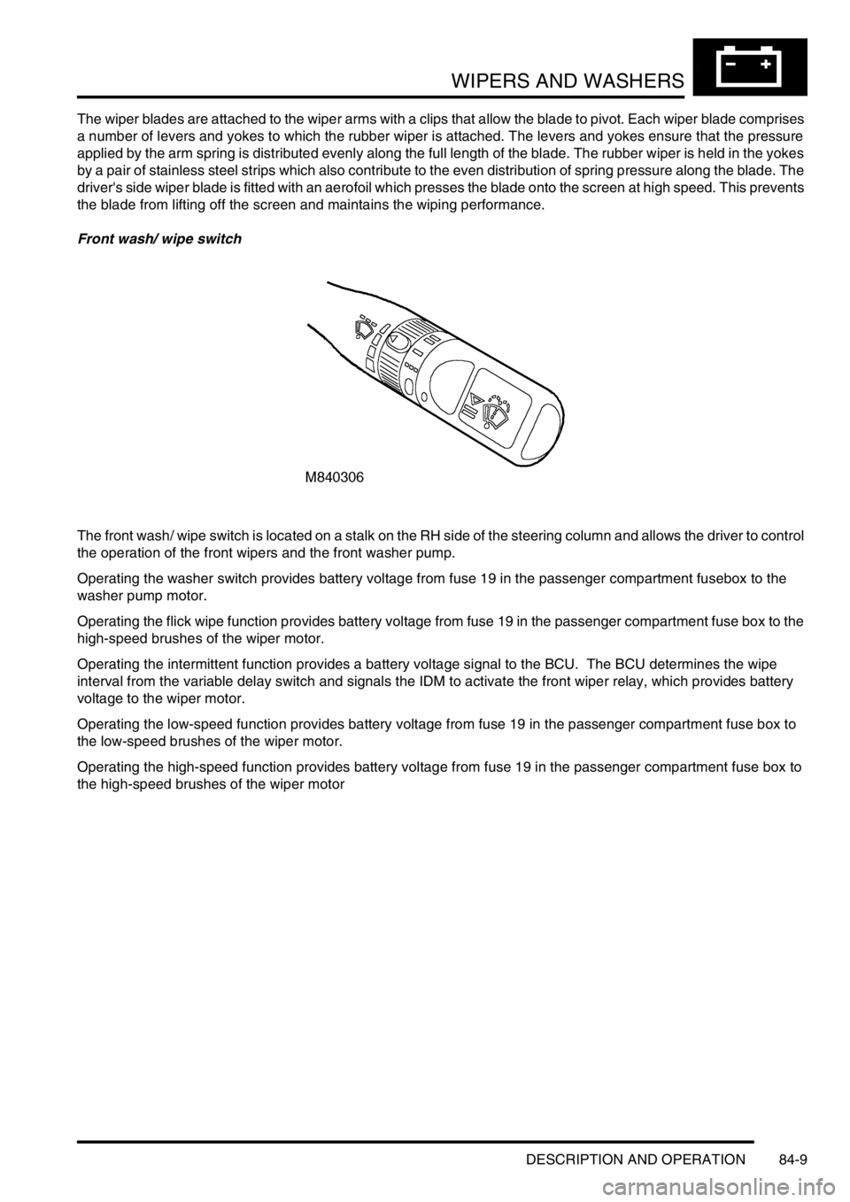
Front wash/ wipe switch
The front wash/ wipe switch is located on a stalk on the RH side of the steering column and allows the driver to control
the operation of the front wipers and the front washer pump.
Operating the washer switch provides battery voltage from fuse 19 in the passenger compartment fusebox to the
washer pump motor.
Operating the flick wipe function provides battery voltage from fuse 19 in the passenger compartment fuse box to the
high-speed brushes of the wiper motor.
Operating the intermittent function provides a battery voltage signal to the BCU. The BCU determines the wipe
interval from the variable delay switch and signals the IDM to activate the front wiper relay, which provides battery
voltage to the wiper motor.
Operating the low-speed function provides battery voltage from fuse 19 in the passenger compartment fuse box to
the low-speed brushes of the wiper motor.
Operating the high-speed function provides battery voltage from fuse 19 in the passenger compartment fuse box to
the high-speed brushes of the wiper motor