warning LAND ROVER DISCOVERY 2002 Owner's Guide
[x] Cancel search | Manufacturer: LAND ROVER, Model Year: 2002, Model line: DISCOVERY, Model: LAND ROVER DISCOVERY 2002Pages: 1672, PDF Size: 46.1 MB
Page 179 of 1672
ENGINE - TD5
12-1-40 REPAIRS
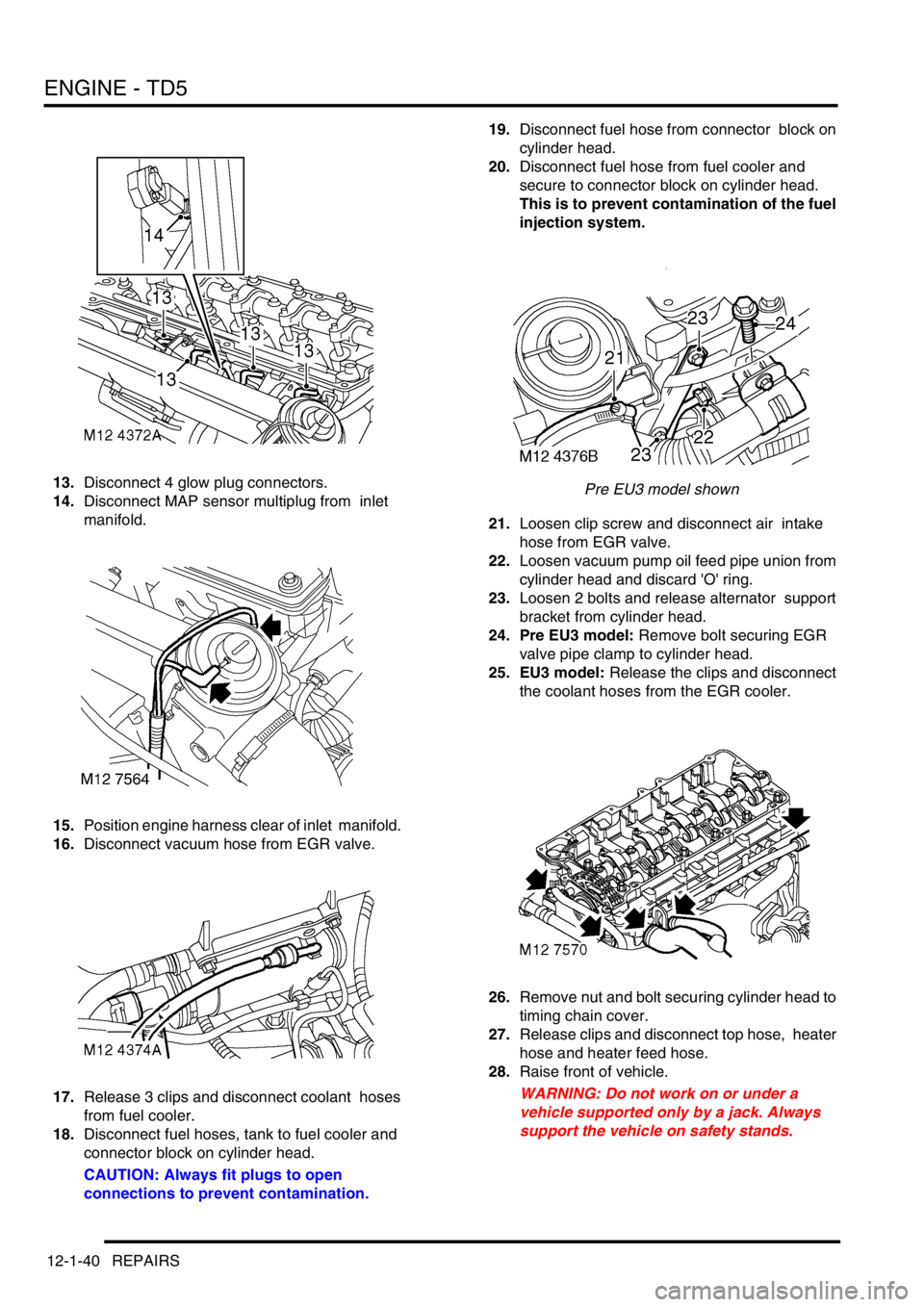
13.Disconnect 4 glow plug connectors.
14.Disconnect MAP sensor multiplug from inlet
manifold.
15.Position engine harness clear of inlet manifold.
16.Disconnect vacuum hose from EGR valve.
17.Release 3 clips and disconnect coolant hoses
from fuel cooler.
18.Disconnect fuel hoses, tank to fuel cooler and
connector block on cylinder head.
CAUTION: Always fit plugs to open
connections to prevent contamination.19.Disconnect fuel hose from connector block on
cylinder head.
20.Disconnect fuel hose from fuel cooler and
secure to connector block on cylinder head.
This is to prevent contamination of the fuel
injection system.
Pre EU3 model shown
21.Loosen clip screw and disconnect air intake
hose from EGR valve.
22.Loosen vacuum pump oil feed pipe union from
cylinder head and discard 'O' ring.
23.Loosen 2 bolts and release alternator support
bracket from cylinder head.
24. Pre EU3 model: Remove bolt securing EGR
valve pipe clamp to cylinder head.
25. EU3 model: Release the clips and disconnect
the coolant hoses from the EGR cooler.
26.Remove nut and bolt securing cylinder head to
timing chain cover.
27.Release clips and disconnect top hose, heater
hose and heater feed hose.
28.Raise front of vehicle.
WARNING: Do not work on or under a
vehicle supported only by a jack. Always
support the vehicle on safety stands.
Page 193 of 1672
ENGINE - TD5
12-1-54 REPAIRS
Mounting - front - RH
$% 12.45.03
Remove
1.Remove fixings and remove engine acoustic
cover.
2.Release fixings and remove battery cover.
3.Disconnect battery earth lead.
4.Raise front of vehicle.
WARNING: Do not work on or under a
vehicle supported only by a jack. Always
support the vehicle on safety stands.
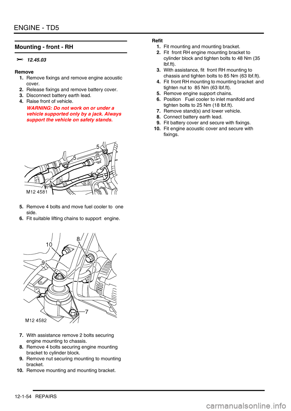
5.Remove 4 bolts and move fuel cooler to one
side.
6.Fit suitable lifting chains to support engine.
7.With assistance remove 2 bolts securing
engine mounting to chassis.
8.Remove 4 bolts securing engine mounting
bracket to cylinder block.
9.Remove nut securing mounting to mounting
bracket.
10.Remove mounting and mounting bracket. Refit
1.Fit mounting and mounting bracket.
2.Fit front RH engine mounting bracket to
cylinder block and tighten bolts to 48 Nm (35
lbf.ft).
3.With assistance, fit front RH mounting to
chassis and tighten bolts to 85 Nm (63 lbf.ft).
4.Fit front RH mounting to mounting bracket and
tighten nut to 85 Nm (63 lbf.ft).
5.Remove engine support chains.
6.Position Fuel cooler to inlet manifold and
tighten bolts to 25 Nm (18 lbf.ft).
7.Remove stand(s) and lower vehicle.
8.Connect battery earth lead.
9.Fit battery cover and secure with fixings.
10.Fit engine acoustic cover and secure with
fixings.
Page 203 of 1672
ENGINE - TD5
12-1-64 REPAIRS
Refit
1.Clean oil cooler and mating faces.
2.Fit oil pressure switch and tighten to 9 Nm (7
lbf.ft).
3.Position new gasket and fit oil cooler housing,
tighten bolts to 25 Nm (18 lbf.ft).
4.Position and fit oil filter adaptor housing,
tighten bolts to 25 Nm (18 lbf. ft).
5.Fit oil filter, tighten hand tight then a further half
turn.
6.Position coolant hose to oil cooler and secure
clip.
7.Position coolant pipe bolt and tighten to 50 Nm
(37 lbf.ft) .
8.Connect multiplug to oil pressure switch.
9.Fit centrifuge assembly.
+ ENGINE - Td5, REPAIRS, Gasket -
centrifuge oil drain pipe.
10.Refill cooling system.
+ COOLING SYSTEM - Td5,
ADJUSTMENTS, Drain and refill.
11.Top up engine oil.
+ MAINTENANCE, PROCEDURES,
Engine oil - diesel engine.
Gasket - centrifuge oil drain pipe
$% 12.60.90
Remove
1.Raise front of vehicle.
WARNING: Do not work on or under a
vehicle supported only by a jack. Always
support the vehicle on safety stands.
2.Remove fixings and remove underbelly panel.
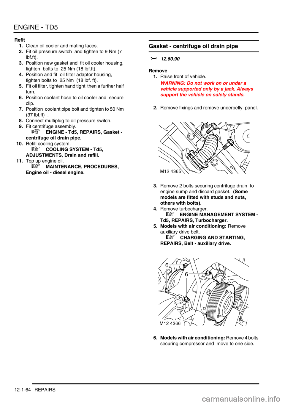
3.Remove 2 bolts securing centrifuge drain to
engine sump and discard gasket. (Some
models are fitted with studs and nuts,
others with bolts).
4.Remove turbocharger.
+ ENGINE MANAGEMENT SYSTEM -
Td5, REPAIRS, Turbocharger.
5. Models with air conditioning: Remove
auxiliary drive belt.
+ CHARGING AND STARTING,
REPAIRS, Belt - auxiliary drive.
6. Models with air conditioning: Remove 4 bolts
securing compressor and move to one side.
Page 228 of 1672

ENGINE - TD5
OVERHAUL 12-1-89
Reassembly
1.Clean drive plate, spacer, starter ring gear and
crankshaft mating faces.
2.Position starter ring gear on crankshaft, fit
spacer and drive plate.
3.Fit new bolts to retain assembly and tighten by
diagonal selection to:
lStage 1 - 40 Nm (30 lbf.ft)
lStage 2 - Further 90
°
CAUTION: Do not carry out stages 1 and 2 in
one operation.
4.Remove tool LRT-51-003, fit damper and
tighten bolts to 80 Nm (59 lbf.ft).
Starter ring gear
$% 12.53.19
Disassembly
1. Manual models: Remove flywheel.
+ ENGINE - Td5, OVERHAUL,
Flywheel.
2. Automatic models: Remove drive plate.
+ ENGINE - Td5, OVERHAUL, Drive
plate.
3.Drill a 3 mm (0.12 in) diameter hole at root of 2
teeth.
4.Apply a cold chisel to root of teeth, break ring
gear and remove from flywheel.
WARNING: SUITABLE EYE PROTECTION
MUST BE WORN.
Reassembly
1.Heat ring gear evenly to 350
° C, indicated by
light blue colour.
2.Locate ring gear on to flywheel and press on to
flange.
3.Allow ring gear to air cool.
4. Manual models: Fit flywheel.
+ ENGINE - Td5, OVERHAUL,
Flywheel.
5. Automatic models: Fit drive plate.
+ ENGINE - Td5, OVERHAUL, Drive
plate.
Page 232 of 1672
ENGINE - TD5
OVERHAUL 12-1-93
Timing chain and sprockets
$% 12.65.13.01
Disassembly
1.Remove cylinder head gasket.
+ ENGINE - Td5, OVERHAUL, Gasket
- cylinder head.
CAUTION: If timing chain tensioner is to be
replaced, ensure tensioner is correct for
engine. Tensioner bodies are colour coded
as follows: Engine Serial No. Prefixes 10P to
14P – BLACK with, additionally on later
engines, YELLOW on tensioner hex. head.
Serial No. Prefixes 15P to 19P – body is
colour coded YELLOW. Later tensioners
may be fitted to early engines provided that
the modified adjustable guide is also fitted.
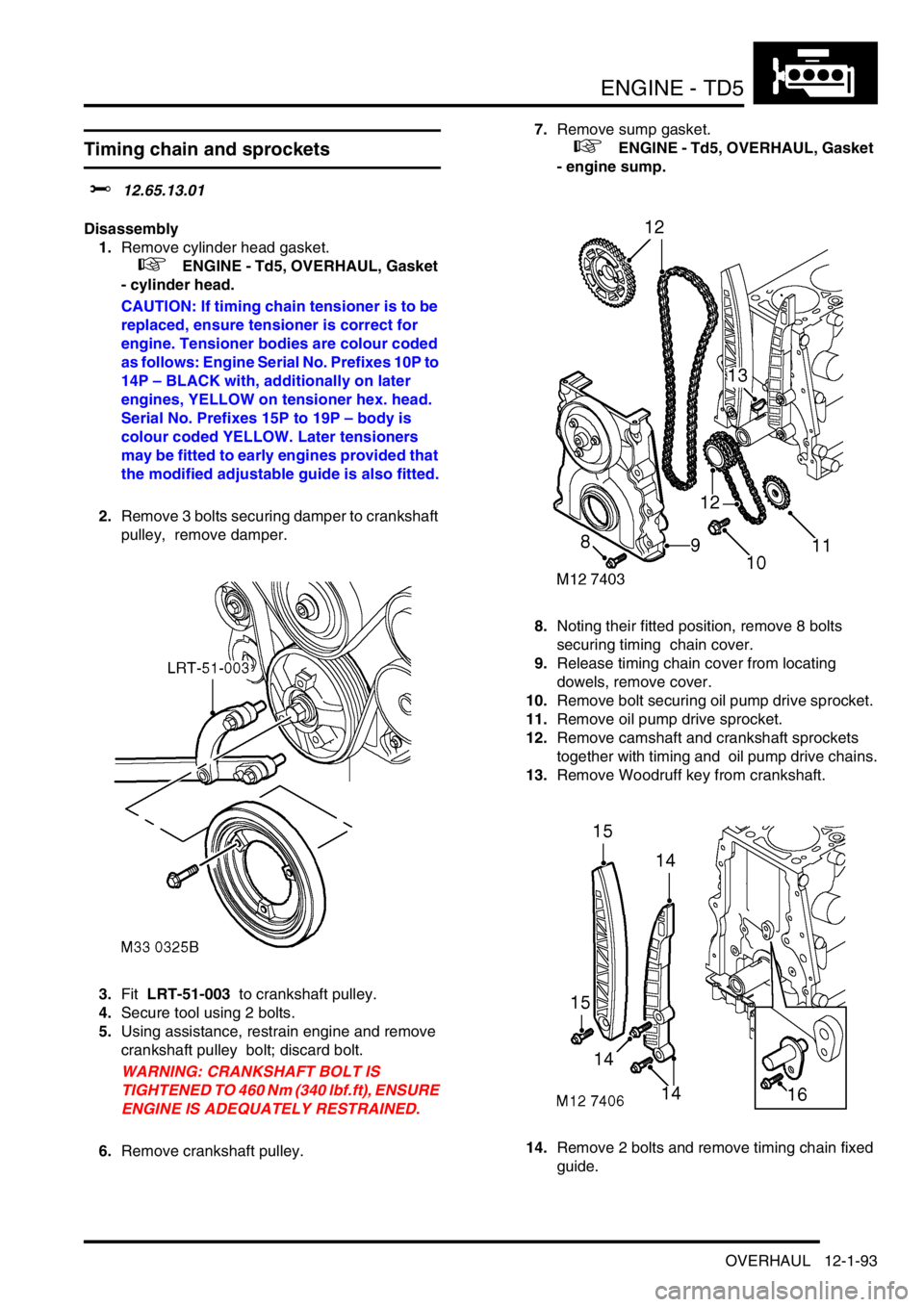
2.Remove 3 bolts securing damper to crankshaft
pulley, remove damper.
3.Fit LRT-51-003 to crankshaft pulley.
4.Secure tool using 2 bolts.
5.Using assistance, restrain engine and remove
crankshaft pulley bolt; discard bolt.
WARNING: CRANKSHAFT BOLT IS
TIGHTENED TO 460 Nm (340 lbf.ft), ENSURE
ENGINE IS ADEQUATELY RESTRAINED.
6.Remove crankshaft pulley.7.Remove sump gasket.
+ ENGINE - Td5, OVERHAUL, Gasket
- engine sump.
8.Noting their fitted position, remove 8 bolts
securing timing chain cover.
9.Release timing chain cover from locating
dowels, remove cover.
10.Remove bolt securing oil pump drive sprocket.
11.Remove oil pump drive sprocket.
12.Remove camshaft and crankshaft sprockets
together with timing and oil pump drive chains.
13.Remove Woodruff key from crankshaft.
14.Remove 2 bolts and remove timing chain fixed
guide.
Page 235 of 1672
ENGINE - TD5
12-1-96 OVERHAUL
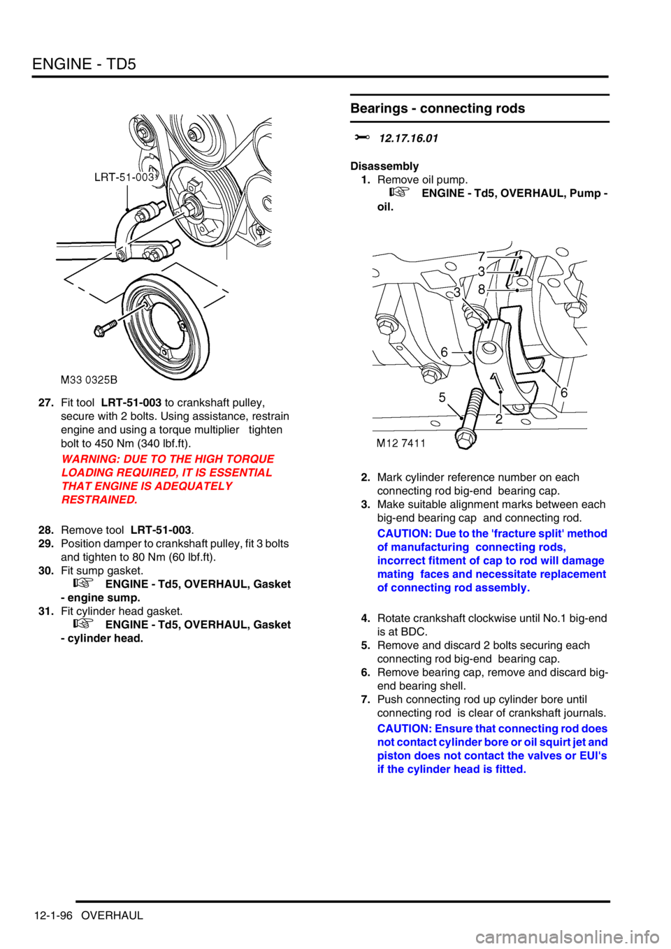
27.Fit tool LRT-51-003 to crankshaft pulley,
secure with 2 bolts. Using assistance, restrain
engine and using a torque multiplier tighten
bolt to 450 Nm (340 lbf.ft).
WARNING: DUE TO THE HIGH TORQUE
LOADING REQUIRED, IT IS ESSENTIAL
THAT ENGINE IS ADEQUATELY
RESTRAINED.
28.Remove tool LRT-51-003.
29.Position damper to crankshaft pulley, fit 3 bolts
and tighten to 80 Nm (60 lbf.ft).
30.Fit sump gasket.
+ ENGINE - Td5, OVERHAUL, Gasket
- engine sump.
31.Fit cylinder head gasket.
+ ENGINE - Td5, OVERHAUL, Gasket
- cylinder head.
Bearings - connecting rods
$% 12.17.16.01
Disassembly
1.Remove oil pump.
+ ENGINE - Td5, OVERHAUL, Pump -
oil.
2.Mark cylinder reference number on each
connecting rod big-end bearing cap.
3.Make suitable alignment marks between each
big-end bearing cap and connecting rod.
CAUTION: Due to the 'fracture split' method
of manufacturing connecting rods,
incorrect fitment of cap to rod will damage
mating faces and necessitate replacement
of connecting rod assembly.
4.Rotate crankshaft clockwise until No.1 big-end
is at BDC.
5.Remove and discard 2 bolts securing each
connecting rod big-end bearing cap.
6.Remove bearing cap, remove and discard big-
end bearing shell.
7.Push connecting rod up cylinder bore until
connecting rod is clear of crankshaft journals.
CAUTION: Ensure that connecting rod does
not contact cylinder bore or oil squirt jet and
piston does not contact the valves or EUI's
if the cylinder head is fitted.
Page 252 of 1672

ENGINE - V8
DESCRIPTION AND OPERATION 12-2-9
element. Oil from the filter passes into the main oil gallery and through internal drillings to the crankshaft where it is
directed to each main bearing and to the big-end bearings via numbers 1, 3 and 5 main bearings. An internal drilling
in the cylinder block directs oil to the camshaft where it passes through further internal drillings to the hydraulic
tappets, camshaft bearing journals and rocker shafts. Lubrication to the pistons, small ends and cylinder bores is by
oil grooves machined in the connecting rods and by splash.
Oil pressure switch
The oil pressure warning light switch registers low oil pressure in the main oil gallery on the outflow side of the filter.
Whilst the engine is running and oil pressure is correct, the switch is open. When the ignition is switched on or if oil
pressure drops below the pressure setting of the switch, the switch closes and the low oil pressure warning lamp
located in the instrument pack will illuminate.
Hydraulic tappets
1Clip
2Pushrod seat
3Inner sleeve
4Upper chamber5Non-return ball valve
6Spring
7Outer sleeve
8Lower chamber
The hydraulic tappet provides maintenance free, quiet operation of the valves. This is achieved by utilizing engine oil
pressure to eliminate the clearance between the rocker arms and valve stems. When the valve is closed, engine oil
pressure present in the upper chamber, passes through the non-return ball valve and into the lower chamber. When
the cam begins to lift the outer sleeve, the resistance of the valve spring, felt through the push rod and seat, causes
the tappet inner sleeve to move downwards inside the outer sleeve. This downwards movement closes the non-return
ball valve and increases the pressure in the lower chamber sufficiently to ensure that the valve is fully opened by the
push rod. As the tappet moves off the peak of the cam, the non-return ball valve opens thereby allowing the pressure
in both chambers to equalize. This ensures that the valve will be fully closed when the tappet is on the back of the
cam.
Crankcase ventilation
A positive crankcase ventilation system is used to vent crankcase gases to the air induction system. Gases are drawn
from the left hand rocker cover to a tapping in the throttle body. An oil separator is incorporated in the hose connection
stub pipe in the right hand rocker cover, gases from this connection are drawn to a tapping in the inlet manifold.
+ EMISSION CONTROL - V8, DESCRIPTION AND OPERATION, Crankcase emission control system.
Page 265 of 1672

ENGINE - V8
12-2-22 REPAIRS
Mounting - front - LH
$% 12.45.01
Remove
1.Release turnbuckles and remove battery cover.
2.Disconnect battery earth lead.
3.Raise front of vehicle.
WARNING: Do not work on or under a
vehicle supported only by a jack. Always
support the vehicle on safety stands.
4.Remove underbelly panel.
+ EXTERIOR FITTINGS, REPAIRS,
Panel - underbelly.
5.Position a jack beneath the sump, and support
the engine on the jack.
CAUTION: To prevent damage to
components, cushion the jack pad with a
block of wood or hard rubber.
6.Remove 2 nuts securing engine mountings to
chassis.
7.Remove nut securing LH mounting to cylinder
block.
8.Raise engine sufficiently to allow engine
mounting to be removed, take care not to trap
any cables, pipes or harness.
9.Remove engine mounting. Collect heat shield,
if fitted.Refit
1.Fit heat shield to engine mounting, if fitted.
2.Fit engine mounting ensuring dowel is located.
3.Lower the jack and engage engine mounting
studs in chassis.
4.Fit nuts securing LH engine mounting and
tighten to 85 Nm (63 lbf.ft).
5.Fit underbelly panel.
+ EXTERIOR FITTINGS, REPAIRS,
Panel - underbelly.
6.Remove stand(s) and lower vehicle.
7.Connect battery earth lead.
8.Fit battery cover and secure turnbuckles.
Page 266 of 1672

ENGINE - V8
REPAIRS 12-2-23
Mounting - front - RH
$% 12.45.03
Remove
1.Release turnbuckles and remove battery cover.
2.Disconnect battery earth lead.
3.Raise front of vehicle.
WARNING: Do not work on or under a
vehicle supported only by a jack. Always
support the vehicle on safety stands.
4.Remove underbelly panel.
+ EXTERIOR FITTINGS, REPAIRS,
Panel - underbelly.
5.Position a jack beneath the sump, and support
the engine on the jack.
CAUTION: To prevent damage to
components, cushion the jack pad with a
block of wood or hard rubber.
6.Remove 2 nuts securing engine mountings to
chassis.
7.Remove nut securing RH mounting to cylinder
block.
8.Raise engine sufficiently to allow engine
mounting to be removed. Take care not to trap
any cables, pipes or harness.
9.Remove engine mounting.
10.Collect heat shield. Refit
1.Position heat shield.
2.Fit engine mounting ensuring dowel is located.
3.Lower the jack and engage engine mounting
studs in chassis.
4.Fit engine mounting nuts and tighten to 85 Nm
(63 lbf.ft).
5.Fit underbelly panel.
+ EXTERIOR FITTINGS, REPAIRS,
Panel - underbelly.
6.Remove stand(s) and lower vehicle.
7.Connect battery earth lead.
8.Fit battery cover and secure turnbuckles.
Page 276 of 1672
ENGINE - V8
REPAIRS 12-2-33
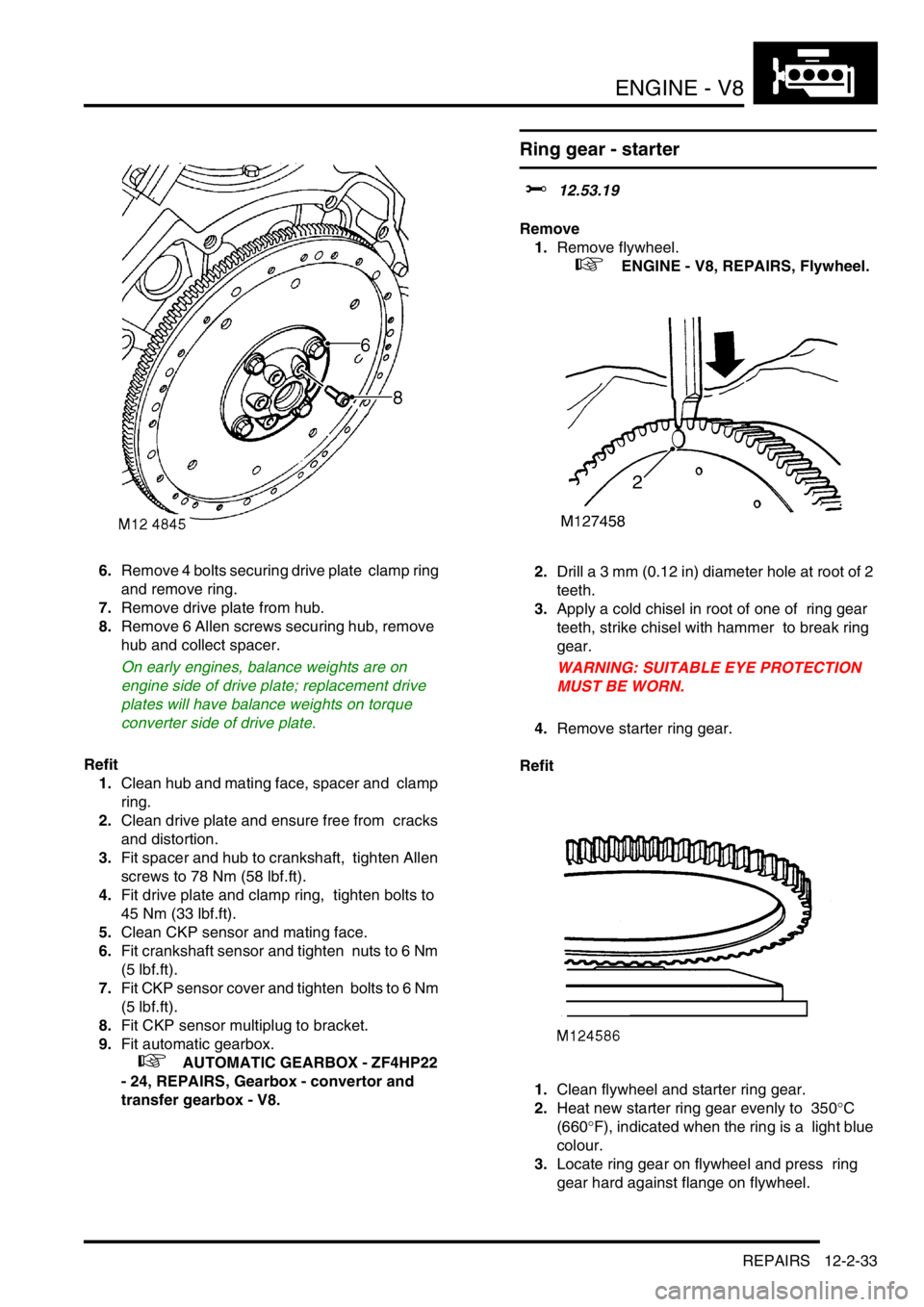
6.Remove 4 bolts securing drive plate clamp ring
and remove ring.
7.Remove drive plate from hub.
8.Remove 6 Allen screws securing hub, remove
hub and collect spacer.
On early engines, balance weights are on
engine side of drive plate; replacement drive
plates will have balance weights on torque
converter side of drive plate.
Refit
1.Clean hub and mating face, spacer and clamp
ring.
2.Clean drive plate and ensure free from cracks
and distortion.
3.Fit spacer and hub to crankshaft, tighten Allen
screws to 78 Nm (58 lbf.ft).
4.Fit drive plate and clamp ring, tighten bolts to
45 Nm (33 lbf.ft).
5.Clean CKP sensor and mating face.
6.Fit crankshaft sensor and tighten nuts to 6 Nm
(5 lbf.ft).
7.Fit CKP sensor cover and tighten bolts to 6 Nm
(5 lbf.ft).
8.Fit CKP sensor multiplug to bracket.
9.Fit automatic gearbox.
+ AUTOMATIC GEARBOX - ZF4HP22
- 24, REPAIRS, Gearbox - convertor and
transfer gearbox - V8.
Ring gear - starter
$% 12.53.19
Remove
1.Remove flywheel.
+ ENGINE - V8, REPAIRS, Flywheel.
2.Drill a 3 mm (0.12 in) diameter hole at root of 2
teeth.
3.Apply a cold chisel in root of one of ring gear
teeth, strike chisel with hammer to break ring
gear.
WARNING: SUITABLE EYE PROTECTION
MUST BE WORN.
4.Remove starter ring gear.
Refit
1.Clean flywheel and starter ring gear.
2.Heat new starter ring gear evenly to 350
°C
(660
°F), indicated when the ring is a light blue
colour.
3.Locate ring gear on flywheel and press ring
gear hard against flange on flywheel.