warning LAND ROVER DISCOVERY 2002 Owner's Manual
[x] Cancel search | Manufacturer: LAND ROVER, Model Year: 2002, Model line: DISCOVERY, Model: LAND ROVER DISCOVERY 2002Pages: 1672, PDF Size: 46.1 MB
Page 123 of 1672

MAINTENANCE
10-14 PROCEDURES
Intercooler - diesel engine
Remove
1.Remove intercooler.
+ ENGINE MANAGEMENT SYSTEM -
Td5, REPAIRS, Intercooler.
Flush
1.Flush intercooler element using Flushing
Solvent Part No. STC 9713, following the
manufacturer's instructions.
2.Thoroughly dry intercooler ensuring that no
trace of solvent remains in the element.
3.Refit intercooler on completion.
+ ENGINE MANAGEMENT SYSTEM -
Td5, REPAIRS, Intercooler.
Engine oil - V8 engine
WARNING: Avoid excessive skin contact with
used engine oil. Used engine oil contains
potentially harmful contaminants which may
cause skin cancer or other serious skin
disorders.
Replace
1.Position suitable container beneath sump.
2.Clean area around oil drain plug.
3.Remove oil drain plug, discard sealing washer.
4.Allow oil to drain.
5.Fit new sealing washer to oil drain plug.
6.Fit engine drain plug and tighten to 33 Nm (24
lbf.ft).
7.Fill engine with recommended grade of oil to
correct mark on dipstick.
+ CAPACITIES, FLUIDS AND
LUBRICANTS, Lubrication.
Engine oil - diesel engine
WARNING: Avoid excessive skin contact with
used engine oil. Used engine oil contains
potentially harmful contaminants which may
cause skin cancer or other serious skin
disorders.
Replace
1.Release fixings, remove underbelly panel.
2.Position suitable container beneath sump.
3.Clean area around drain plug.
4.Remove oil drain plug, discard sealing washer.
5.Allow oil to drain.
6.Fit new sealing washer to oil drain plug.
7.Fit engine drain plug and tighten to 23 Nm (17
lbf.ft).
8.Fill engine with recommended grade of oil to
correct mark on dipstick.
+ CAPACITIES, FLUIDS AND
LUBRICANTS, Lubrication.
9.Fit front underbelly panel, secure fixings.
Page 124 of 1672

MAINTENANCE
PROCEDURES 10-15
Centrifuge rotor – diesel engine
Replace
1.Replace centrifuge rotor.
+ ENGINE - Td5, REPAIRS, Rotor -
centrifuge.
Engine oil filter - diesel engine
Replace
1.Replace oil filter.
+ ENGINE - Td5, REPAIRS, Filter - oil.
Engine oil filter – V8 engine
WARNING: Avoid excessive skin contact with
used engine oil. Used engine oil contains
potentially harmful contaminants which may
cause skin cancer or other serious skin
disorders.
Replace
1.Disconnect battery.
2.Position suitable container beneath oil filter.
3.Using a strap type filter wrench, remove filter
element, discard element.
4.Smear sealing ring of replacement filter
element with engine oil.
5.Fit filter element, tighten two thirds of a turn by
hand or to 17 Nm (13 lbf.ft).
6.Top-up engine with recommended grade of oil
to correct mark on dipstick.
+ CAPACITIES, FLUIDS AND
LUBRICANTS, Lubrication.
7.Connect battery.
8.Run engine and check for oil leaks from filter.
9.Stop engine, wait for oil to return to sump.
10.Re-check oil level and top-up if necessary.
Page 125 of 1672

MAINTENANCE
10-16 PROCEDURES
Manual gearbox
WARNING: Avoid excessive skin contact with
mineral oil. Mineral oils remove the natural fats
from the skin, leading to dryness, irritation and
dermatitis.
Check/top-up oil level
1.Release fixings, remove rear underbelly panel.
2.Clean area around oil filler/level plug.
3.Remove oil filler/level plug.
4.Check that oil level is to bottom of oil filler/level
plug hole.
5.Top-up level (if required) with recommended oil
to bottom of filler/level plug hole.
+ CAPACITIES, FLUIDS AND
LUBRICANTS, Lubrication.
6.Remove all traces of sealant from threads of oil
filler/level plug.
7.Apply Loctite 290 to threads of oil filler/level
plug.
8. Fit manual gearbox filler/level plug and tighten
to 30 Nm (22 lbf.ft).
9.Remove all traces of oil from gearcase.
10.Fit rear underbelly panel, secure fixings.
Replace oil
1.Release fixings, remove rear underbelly panel.
2.Place a suitable container beneath gearbox
drain plug.
3.Clean area around oil filler/level and drain
plugs.4.Remove oil filler/level plug.
5.Remove oil drain plug, remove and discard
sealing washer.
6.Allow oil to drain.
7.Clean magnet in oil drain plug.
8.Fit new sealing washer to oil drain plug.
9.Fit manual gearbox drain plug and tighten to 50
Nm (37 lbf.ft).
10.Fill gearbox with recommended oil to bottom of
filler/level plug hole.
+ CAPACITIES, FLUIDS AND
LUBRICANTS, Lubrication.
11.Remove all traces of sealant from threads of oil
filler/level plug.
12.Apply Loctite 290 to threads of oil filler/level
plug.
13. Fit manual gearbox filler/level plug and tighten
to 30 Nm (22 lbf.ft).
14.Remove all traces of oil from gearcase.
15.Fit rear underbelly panel, secure fixings.
Page 126 of 1672

MAINTENANCE
PROCEDURES 10-17
Automatic gearbox
WARNING: Avoid excessive skin contact with
mineral oil. Mineral oils remove the natural fats
from the skin, leading to dryness, irritation and
dermatitis.
Replace oil filter
1.Replace oil filter.
+ AUTOMATIC GEARBOX - ZF4HP22
- 24, REPAIRS, Filter - oil.
Replace oil
1. Ensure that gearbox is cool. Apply
handbrake and securely chock front and rear
wheels.
2.Place a suitable container beneath gearbox.
3.Clean area around oil filler/level and drain
plugs.
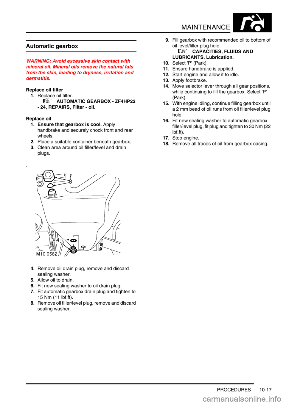
4.Remove oil drain plug, remove and discard
sealing washer.
5.Allow oil to drain.
6.Fit new sealing washer to oil drain plug.
7.Fit automatic gearbox drain plug and tighten to
15 Nm (11 lbf.ft).
8.Remove oil filler/level plug, remove and discard
sealing washer.9.Fill gearbox with recommended oil to bottom of
oil level/filler plug hole.
+ CAPACITIES, FLUIDS AND
LUBRICANTS, Lubrication.
10.Select 'P' (Park).
11.Ensure handbrake is applied.
12.Start engine and allow it to idle.
13.Apply footbrake.
14.Move selector lever through all gear positions,
while continuing to fill the gearbox. Select 'P'
(Park).
15.With engine idling, continue filling gearbox until
a 2 mm bead of oil runs from oil filler/level plug
hole.
16.Fit new sealing washer to automatic gearbox
filler/level plug, fit plug and tighten to 30 Nm (22
l b f . f t ) .
17.Stop engine.
18.Remove all traces of oil from gearbox casing.
Page 127 of 1672

MAINTENANCE
10-18 PROCEDURES
Transfer box
WARNING: Avoid excessive skin contact with
mineral oil. Mineral oils remove the natural fats
from the skin, leading to dryness, irritation and
dermatitis.
Check/top-up oil level
1.Release fixings, remove rear underbelly panel.
2.Clean area around oil filler/level plug.
3.Remove oil filler/level plug.
4.Check that oil level is to bottom of filler/level
plug hole.
5.Top-up level (if required) with recommended oil
to bottom of oil filler/level plug hole.
+ CAPACITIES, FLUIDS AND
LUBRICANTS, Lubrication.
6.Remove all traces of sealant from threads of oil
filler/level plug.
7.Apply Loctite 290 to threads of oil filler/level
plug.
8. Fit transfer box filler/level plug and tighten to 25
Nm (18 lbf.ft).
9.Remove all traces of oil from main casing.
10.Fit rear underbelly panel (if fitted), secure
fixings.Replace oil
1. Release fixings, remove rear underbelly panel.
2.Place a suitable container beneath transfer box
drain plug.
3.Clean area around oil filler/level and drain
plugs.
4.Remove oil filler/level plug.
5.Remove oil drain plug.
6.Allow oil to drain.
7.Apply Loctite 290 to threads of oil drain plug.
8. Fit transfer box drain plug and tighten to 30
Nm (22 lbf.ft).
9.Fill transfer box with recommended oil to
bottom of oil filler/level plug hole.
+ CAPACITIES, FLUIDS AND
LUBRICANTS, Lubrication.
10.Remove all traces of sealant from threads of oil
filler/level plug.
11.Apply Loctite 290 to threads of oil filler/level
plug.
12. Fit transfer box filler/level plug and tighten to 25
Nm (18 lbf.ft).
13. Remove all traces of oil from transfer box.
14.Fit rear underbelly panel (if fitted), secure
fixings.
Page 128 of 1672

MAINTENANCE
PROCEDURES 10-19
Front and rear axle
WARNING: Avoid excessive skin contact with
mineral oil. Mineral oils remove the natural fats
from the skin, leading to dryness, irritation and
dermatitis.
Replace oil
1.Place a suitable container beneath differential
housing of axle to be drained.
2.Clean area around oil filler/level and drain
plugs.
3.Remove oil filler/level plug.
4.Remove and discard 'O' ring from oil filler/level
plug.
5.Remove oil drain plug, allow oil to drain.
6.Remove all traces of Loctite from threads of oil
drain plug.
7.Apply Loctite 290 to threads of oil drain plug.
8. Fit axle drain plug and tighten to 64 Nm (47
lbf.ft).
9.Fill differential housing with recommended oil to
bottom of oil filler/level plug hole.
+ CAPACITIES, FLUIDS AND
LUBRICANTS, Lubrication.
10.Lubricate a new 'O' ring with recommended oil
and fit to oil filler/level plug.
11.Fit axle filler/level plug and tighten to 10 Nm (7
lbf.ft).
12.Remove all traces of oil from differential
housing.
Propeller shafts
Lubricate
Rear shaft
1.Clean area around front universal joint grease
nipple.
2.Apply recommended grease to the grease
nipple.
+ CAPACITIES, FLUIDS AND
LUBRICANTS, Lubrication.
Front shaft
3.Remove blanking plug adjacent to sliding joint
from propeller shaft.
4.Screw a 1/4in UNF grease nipple into blanking
plug hole.
Page 137 of 1672

MAINTENANCE
10-28 PROCEDURES
4.Check condition of Engine - RH mounting
rubber
5.Check tightness of all mounting bolts.
+ TORQUE WRENCH SETTINGS,
Engine V8.
Road/roller test
WARNING: Roller test must be restricted to 3
mph (5 km/h). If 2 wheel rolling road is to be used,
disconnect propeller shaft from the transfer box
output shaft driving the axle which is NOT on the
rolling road.Testing
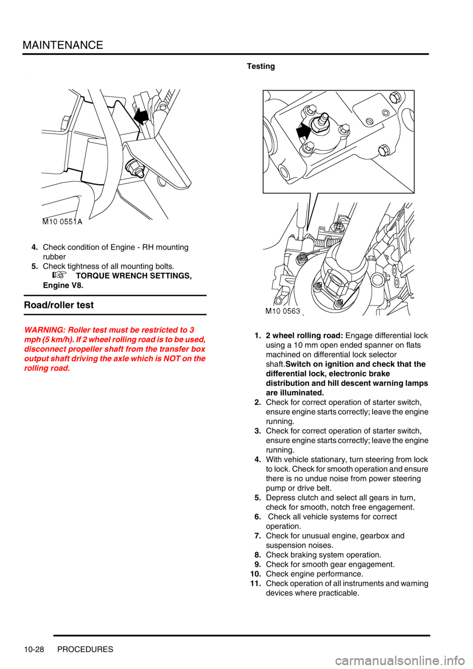
1. 2 wheel rolling road: Engage differential lock
using a 10 mm open ended spanner on flats
machined on differential lock selector
shaft.Switch on ignition and check that the
differential lock, electronic brake
distribution and hill descent warning lamps
are illuminated.
2.Check for correct operation of starter switch,
ensure engine starts correctly; leave the engine
running.
3.Check for correct operation of starter switch,
ensure engine starts correctly; leave the engine
running.
4.With vehicle stationary, turn steering from lock
to lock. Check for smooth operation and ensure
there is no undue noise from power steering
pump or drive belt.
5.Depress clutch and select all gears in turn,
check for smooth, notch free engagement.
6. Check all vehicle systems for correct
operation.
7.Check for unusual engine, gearbox and
suspension noises.
8.Check braking system operation.
9.Check for smooth gear engagement.
10.Check engine performance.
11.Check operation of all instruments and warning
devices where practicable.
Page 138 of 1672

MAINTENANCE
PROCEDURES 10-29
12.Where possible, check for correct operation of
hill descent control (HDC) mechanism. This
should not be carried out if excessive journey
time is required.
13.After road/roller test, carry out a final inspection
of vehicle, with vehicle on a ramp.
14.Check all fluid levels and top-up if necessary.
15. 2 wheel rolling road: Ensure differential lock is
disengaged and propeller shaft is connected on
completion of test. Switch on ignition and
check that differential lock, electronic brake
distribution and hill descent warning lamps
are extinguished.
Page 158 of 1672

ENGINE - TD5
DESCRIPTION AND OPERATION 12-1-19
Oil Pressure switch
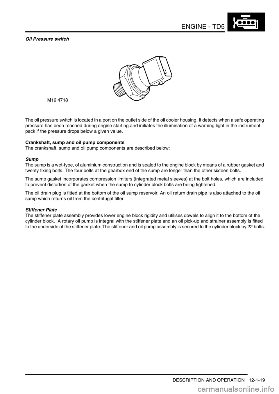
The oil pressure switch is located in a port on the outlet side of the oil cooler housing. It detects when a safe operating
pressure has been reached during engine starting and initiates the illumination of a warning light in the instrument
pack if the pressure drops below a given value.
Crankshaft, sump and oil pump components
The crankshaft, sump and oil pump components are described below:
Sump
The sump is a wet-type, of aluminium construction and is sealed to the engine block by means of a rubber gasket and
twenty fixing bolts. The four bolts at the gearbox end of the sump are longer than the other sixteen bolts.
The sump gasket incorporates compression limiters (integrated metal sleeves) at the bolt holes, which are included
to prevent distortion of the gasket when the sump to cylinder block bolts are being tightened.
The oil drain plug is fitted at the bottom of the oil sump reservoir. An oil return drain pipe is also attached to the oil
sump which returns oil from the centrifugal filter.
Stiffener Plate
The stiffener plate assembly provides lower engine block rigidity and utilises dowels to align it to the bottom of the
cylinder block. A rotary oil pump is integral with the stiffener plate and an oil pick-up and strainer assembly is fitted
to the underside of the stiffener plate. The stiffener and oil pump assembly is secured to the cylinder block by 22 bolts.
Page 171 of 1672

ENGINE - TD5
12-1-32 DESCRIPTION AND OPERATION
When the engine temperature is below 74° C, the thermostat in the full-flow filter housing is closed and a proportion
of the oil flow to the main oil gallery is diverted to the oil cooler to supply an oil feed to the turbocharger bearings. Oil
passes through the oil cooler to the front gallery in the oil cooler housing where there is a tapping to connect the feed
pipe to the turbocharger. Oil used by the turbocharger bearings is returned to the sump through an oil drain pipe which
connects to a port in the LH side of the cylinder block.
The remainder of the oil flow leaving the full-flow filter outlet is passed into the cylinder block via a port at the rear of
oil cooler rear gallery.
When the oil temperature rises above 74
° C the thermostat in the full-flow filter adaptor housing begins to open to
allow a proportion of the oil from the full-flow filter to pass through the oil cooler before it reaches the main oil gallery
in the cylinder block. In this instance, oil supply to the turbocharger bearings is fed directly from the full-flow filter
without first passing through the oil cooler. Between 74
° C and 88° C the thermostat valve plunger opens by about
9mm to allow proportionally more oil to flow through the oil cooler before being passed to the cylinder block main oil
delivery gallery. Above 88
°C the thermostat valve continues to open by about 1mm for every 10° C increase in
temperature until the valve is fully open, when all the oil flow to the cylinder block is forced to pass to the cylinder block
via the oil cooler.
An oil pressure switch is located in a port in the rear gallery of the oil cooler housing to sense the oil pressure level
before flow enters the main oil gallery in the engine block. A warning lamp in the instrument cluster is switched on if
the oil pressure is detected as being too low.
+ INSTRUMENTS, DESCRIPTION AND OPERATION, Description.
Drillings from the cylinder block main oil gallery direct oil to the crankshaft main bearings and cross drillings in the
crankshaft direct oil to the big-end bearings. An additional five drillings in the cylinder block supply oil at reduced
pressure to the oil squirt jets for piston cooling and gudgeon pin lubrication.
Oil supply from the cylinder block is then passed to the cylinder head galleries through a non-return valve which is
included as an integral item in the lower face of the cylinder head.