gearbox LAND ROVER DISCOVERY 2002 Service Manual
[x] Cancel search | Manufacturer: LAND ROVER, Model Year: 2002, Model line: DISCOVERY, Model: LAND ROVER DISCOVERY 2002Pages: 1672, PDF Size: 46.1 MB
Page 268 of 1672
ENGINE - V8
REPAIRS 12-2-25
Mounting - rear - RH
$% 12.45.09
Remove
1.Raise vehicle on lift.
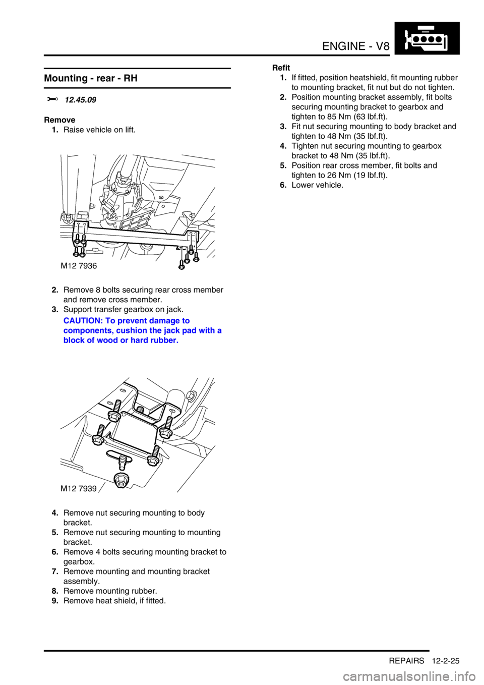
2.Remove 8 bolts securing rear cross member
and remove cross member.
3.Support transfer gearbox on jack.
CAUTION: To prevent damage to
components, cushion the jack pad with a
block of wood or hard rubber.
4.Remove nut securing mounting to body
bracket.
5.Remove nut securing mounting to mounting
bracket.
6.Remove 4 bolts securing mounting bracket to
gearbox.
7.Remove mounting and mounting bracket
assembly.
8.Remove mounting rubber.
9.Remove heat shield, if fitted.Refit
1.If fitted, position heatshield, fit mounting rubber
to mounting bracket, fit nut but do not tighten.
2.Position mounting bracket assembly, fit bolts
securing mounting bracket to gearbox and
tighten to 85 Nm (63 lbf.ft).
3.Fit nut securing mounting to body bracket and
tighten to 48 Nm (35 lbf.ft).
4.Tighten nut securing mounting to gearbox
bracket to 48 Nm (35 lbf.ft).
5.Position rear cross member, fit bolts and
tighten to 26 Nm (19 lbf.ft).
6.Lower vehicle.
Page 272 of 1672
ENGINE - V8
REPAIRS 12-2-29
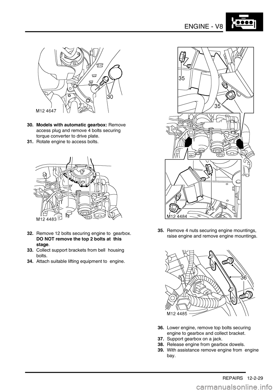
30. Models with automatic gearbox: Remove
access plug and remove 4 bolts securing
torque converter to drive plate.
31.Rotate engine to access bolts.
32.Remove 12 bolts securing engine to gearbox.
DO NOT remove the top 2 bolts at this
stage.
33.Collect support brackets from bell housing
bolts.
34.Attach suitable lifting equipment to engine. 35.Remove 4 nuts securing engine mountings,
raise engine and remove engine mountings.
36.Lower engine, remove top bolts securing
engine to gearbox and collect bracket.
37.Support gearbox on a jack.
38.Release engine from gearbox dowels.
39.With assistance remove engine from engine
bay.
Page 273 of 1672

ENGINE - V8
12-2-30 REPAIRS
Refit
1.Clean mating faces of engine and gearbox,
dowel and dowel holes.
2.Lubricate splines and bearing surface on first
motion shaft with grease.
3.With assistance position engine in engine bay,
align to gearbox and locate on dowels.
4.Position support brackets, fit bell housing bolts
and tighten to 50 Nm (37 lbf.ft).
5.Position engine mountings, fit nuts and tighten
to 85 Nm (63 lbf.ft).
6.Lower lifting equipment and remove from
engine.
7. Models with automatic gearbox: Align torque
converter to drive plate, fit bolts and tighten to
50 Nm (37 lbf.ft). Fit access plug.
8.Fit exhaust front pipe.
+ MANIFOLDS AND EXHAUST
SYSTEMS - V8, REPAIRS, Front pipe.
9.Position oil cooling pipe saddle clamps and
tighten bolts.
10.Position engine harness into foot well.
11.Connect 5 multiplugs to ECM.
12.Fit toe board and secure with trim fixings.
13.Connect engine harness earth to body and
secure with nut.
14.Connect engine harness to main harness
multiplug.
15.Connect multiplug to EVAP purge valve.
16.Connect engine harness multiplugs to fuse
box.
17.Connect starter lead to fuse box and secure
with nut.
18.Connect engine harness positive lead to
battery and tighten nut.
19.Fit fuse box cover.
20.Position engine earth lead and secure with
bolt.
21.Position coolant rail and secure with bolt.
22.Connect harness clips to coolant rail.
23.Connect hose to coolant rail and coolant pump
and secure with clips.
24.Connect PAS pump high and low pressure
pipes and secure with clips.
25.Position oil cooling pipe saddle clamp to PAS
pump housing and secure with bolt.
26.Clean A/C compressor and housing mating
faces, dowels and dowel holes. 27.Position A/C compressor, fit bolts and tighten
to 22 Nm (16 lbf.ft).
28.Connect multiplug to A/C compressor.
29.Clean ACE pump and housing mating faces,
dowels and dowel holes.
30.Position ACE pump, fit bolts and tighten to 22
Nm (16 lbf.ft).
31.Clean all pulley 'V's, fit auxiliary drive belt,
using a 15mm spanner, release belt tensioner
secure belt and re-tension drive belt .
32.Ensure auxiliary drive belt is correctly located
on all pulleys.
33.Fit radiator.
+ COOLING SYSTEM - V8, REPAIRS,
Radiator.
34.Fit top hose and secure with clips.
35.Connect fuel pipe to fuel rail.
36.Position ignition coils and connect ht leads.
37.Fit upper inlet manifold.
+ MANIFOLDS AND EXHAUST
SYSTEMS - V8, REPAIRS, Gasket - inlet
manifold - upper - Without Secondary Air
Injection.
38.Fit new oil filter and refill engine with oil.
+ ENGINE - V8, REPAIRS, Filter - oil.
+ MAINTENANCE, PROCEDURES,
Engine oil - V8 engine.
39.Top up gearbox oil.
+ MAINTENANCE, PROCEDURES,
Automatic gearbox.
Page 274 of 1672
ENGINE - V8
REPAIRS 12-2-31
Flywheel
$% 12.53.07
Remove
1.Remove gearbox
+ MANUAL GEARBOX - R380,
REPAIRS, Gearbox - V8.
2.Restrain flywheel.
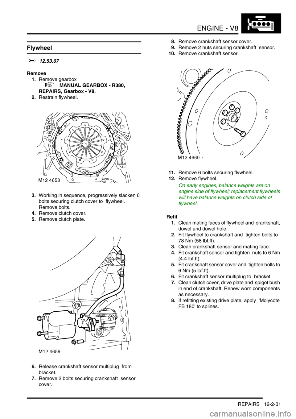
3.Working in sequence, progressively slacken 6
bolts securing clutch cover to flywheel.
Remove bolts.
4.Remove clutch cover.
5.Remove clutch plate.
6.Release crankshaft sensor multiplug from
bracket.
7.Remove 2 bolts securing crankshaft sensor
cover. 8.Remove crankshaft sensor cover.
9.Remove 2 nuts securing crankshaft sensor.
10.Remove crankshaft sensor.
11.Remove 6 bolts securing flywheel.
12.Remove flywheel.
On early engines, balance weights are on
engine side of flywheel; replacement flywheels
will have balance weights on clutch side of
flywheel.
Refit
1.Clean mating faces of flywheel and crankshaft,
dowel and dowel hole.
2.Fit flywheel to crankshaft and tighten bolts to
78 Nm (58 lbf.ft).
3.Clean crankshaft sensor and mating face.
4.Fit crankshaft sensor and tighten nuts to 6 Nm
(4.4 lbf.ft).
5.Fit crankshaft sensor cover and tighten bolts to
6 Nm (5 lbf.ft).
6.Fit crankshaft sensor multiplug to bracket.
7.Clean clutch cover, drive plate and spigot bush
in end of crankshaft. Renew worn components
as necessary.
8.If refitting existing drive plate, apply 'Molycote
FB 180' to splines.
Page 275 of 1672
ENGINE - V8
12-2-32 REPAIRS
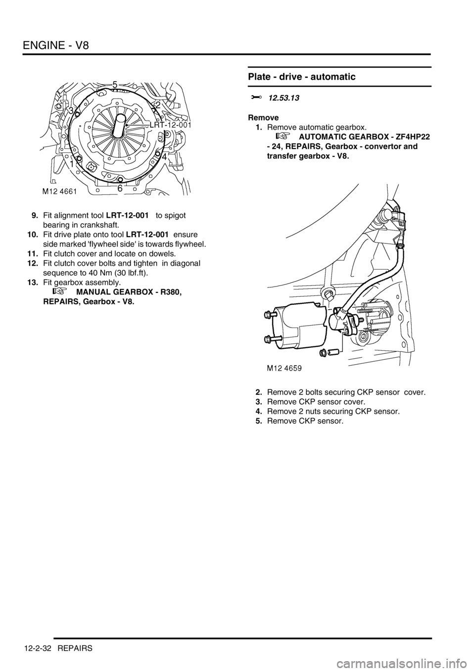
9.Fit alignment tool LRT-12-001 to spigot
bearing in crankshaft.
10.Fit drive plate onto tool LRT-12-001 ensure
side marked 'flywheel side' is towards flywheel.
11.Fit clutch cover and locate on dowels.
12.Fit clutch cover bolts and tighten in diagonal
sequence to 40 Nm (30 lbf.ft).
13.Fit gearbox assembly.
+ MANUAL GEARBOX - R380,
REPAIRS, Gearbox - V8.
Plate - drive - automatic
$% 12.53.13
Remove
1.Remove automatic gearbox.
+ AUTOMATIC GEARBOX - ZF4HP22
- 24, REPAIRS, Gearbox - convertor and
transfer gearbox - V8.
2.Remove 2 bolts securing CKP sensor cover.
3.Remove CKP sensor cover.
4.Remove 2 nuts securing CKP sensor.
5.Remove CKP sensor.
Page 276 of 1672
ENGINE - V8
REPAIRS 12-2-33
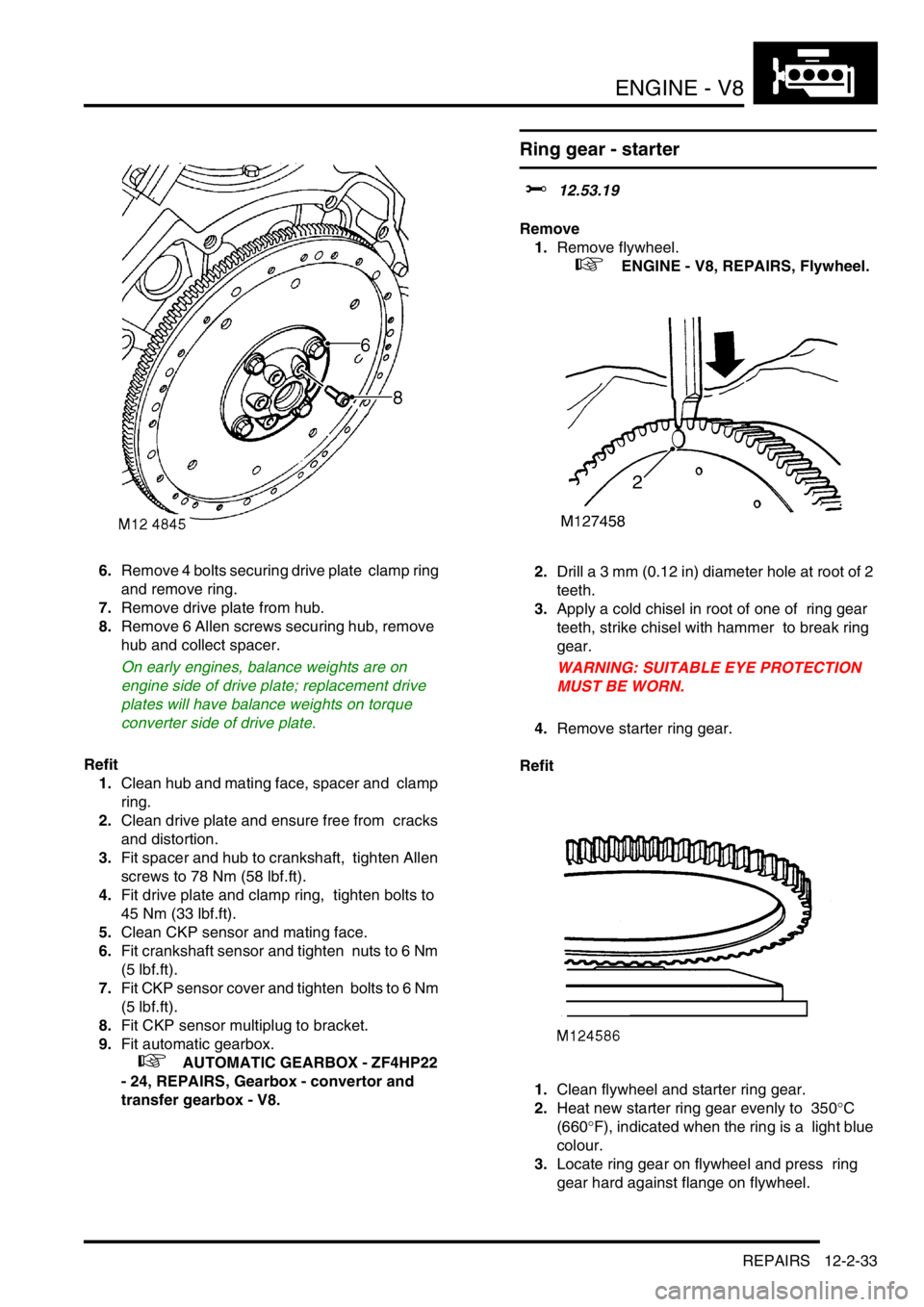
6.Remove 4 bolts securing drive plate clamp ring
and remove ring.
7.Remove drive plate from hub.
8.Remove 6 Allen screws securing hub, remove
hub and collect spacer.
On early engines, balance weights are on
engine side of drive plate; replacement drive
plates will have balance weights on torque
converter side of drive plate.
Refit
1.Clean hub and mating face, spacer and clamp
ring.
2.Clean drive plate and ensure free from cracks
and distortion.
3.Fit spacer and hub to crankshaft, tighten Allen
screws to 78 Nm (58 lbf.ft).
4.Fit drive plate and clamp ring, tighten bolts to
45 Nm (33 lbf.ft).
5.Clean CKP sensor and mating face.
6.Fit crankshaft sensor and tighten nuts to 6 Nm
(5 lbf.ft).
7.Fit CKP sensor cover and tighten bolts to 6 Nm
(5 lbf.ft).
8.Fit CKP sensor multiplug to bracket.
9.Fit automatic gearbox.
+ AUTOMATIC GEARBOX - ZF4HP22
- 24, REPAIRS, Gearbox - convertor and
transfer gearbox - V8.
Ring gear - starter
$% 12.53.19
Remove
1.Remove flywheel.
+ ENGINE - V8, REPAIRS, Flywheel.
2.Drill a 3 mm (0.12 in) diameter hole at root of 2
teeth.
3.Apply a cold chisel in root of one of ring gear
teeth, strike chisel with hammer to break ring
gear.
WARNING: SUITABLE EYE PROTECTION
MUST BE WORN.
4.Remove starter ring gear.
Refit
1.Clean flywheel and starter ring gear.
2.Heat new starter ring gear evenly to 350
°C
(660
°F), indicated when the ring is a light blue
colour.
3.Locate ring gear on flywheel and press ring
gear hard against flange on flywheel.
Page 279 of 1672
ENGINE - V8
12-2-36 REPAIRS
8.Clean coolant pump and mating face.
9.Use a new gasket and fit coolant pump.
Tighten bolts securing coolant pump to 25 Nm
(19 lbf.ft).
10.Ensure CMP sensor is clean and fit sensor to
cover.
11.Fit clamp to CMP sensor and tighten bolt to 8
Nm (6 lbf.ft).
12.Fit timing gear cover gasket.
+ ENGINE - V8, REPAIRS, Gasket -
timing gear cover.
Gasket - sump
$% 12.60.38
Remove
1.Release fixings and remove battery cover.
2.Disconnect battery earth lead.
3.Remove dipstick.
4.Raise the vehicle on a ramp.
5.Drain engine oil.
+ MAINTENANCE, PROCEDURES,
Engine oil - V8 engine.
6.Remove 8 bolts securing cross member and
remove cross member.
7.Raise front of vehicle under body to increase
clearance between engine and front axle.
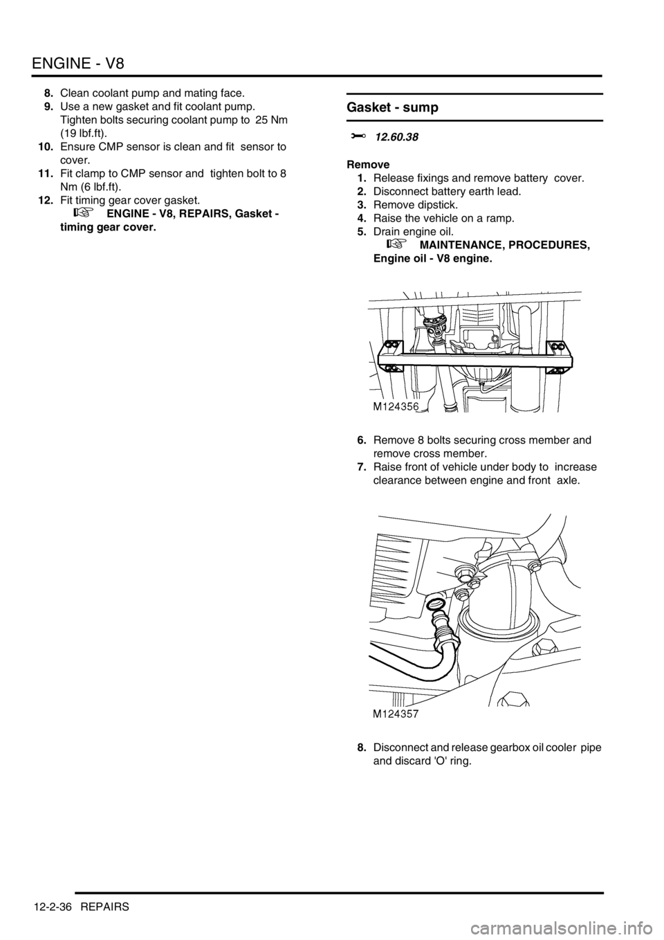
8.Disconnect and release gearbox oil cooler pipe
and discard 'O' ring.
Page 281 of 1672
ENGINE - V8
12-2-38 REPAIRS
8.Clean gearbox oil cooler pipe 'O' ring recess
and mating face.
9.Lubricate and fit new 'O' ring to gearbox oil
cooler pipe.
10.Position pipe and tighten nut.
11.Lower front of vehicle.
12.Position cross member to chassis, fit bolts and
tighten to 25 Nm (18 lbf.ft).
13.Refill engine oil and fit dipstick.
14.Connect battery earth lead.
15.Fit battery cover and retain with fixings.
Switch - oil pressure
$% 12.60.50
Remove
1.Release fixings and remove battery cover.
2.Disconnect battery earth lead.
3.Raise front of vehicle.
WARNING: Do not work on or under a
vehicle supported only by a jack. Always
support the vehicle on safety stands.
4.Remove fixings and remove underbelly panel.
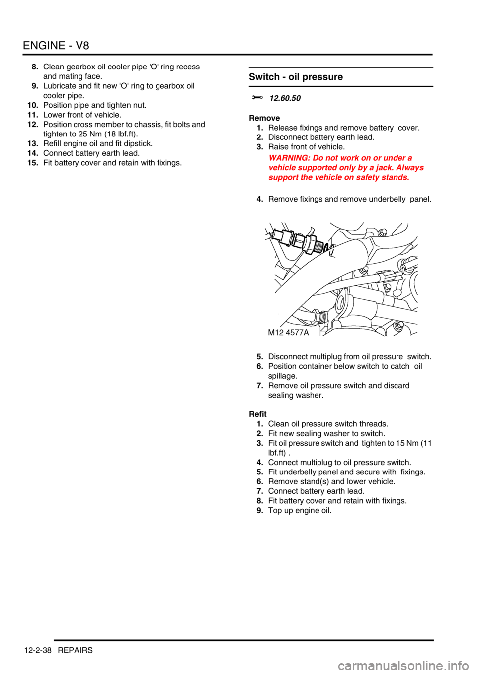
5.Disconnect multiplug from oil pressure switch.
6.Position container below switch to catch oil
spillage.
7.Remove oil pressure switch and discard
sealing washer.
Refit
1.Clean oil pressure switch threads.
2.Fit new sealing washer to switch.
3.Fit oil pressure switch and tighten to 15 Nm (11
lbf.ft) .
4.Connect multiplug to oil pressure switch.
5.Fit underbelly panel and secure with fixings.
6.Remove stand(s) and lower vehicle.
7.Connect battery earth lead.
8.Fit battery cover and retain with fixings.
9.Top up engine oil.
Page 433 of 1672

ENGINE MANAGEMENT SYSTEM - TD5
18-1-40 DESCRIPTION AND OPERATION
Controller Area Network (CAN) system
The CAN system is a high speed serial interface between the ECM and the Electronic Automatic Transmission (EAT)
ECU. The CAN system uses a data bus to transmit information messages between the ECM and the EAT ECU.
Because there are only two components in this CAN system, one will transmit information messages and the other
will receive information messages, and vice-versa.
The CAN system is used by the EAT ECU and the ECM for the following:
lGearshift torque control information.
lEAT OBD information.
lMIL request.
lVehicle speed signal.
lEngine temperature.
lEngine torque and speed.
lGear selected.
lGear change information.
The CAN system uses a twisted pair of wires to form the data bus to minimise electrical interference. This method of
serial interface is very reliable and very fast. The information messages are structured so that each of the receivers
(ECM or EAT ECU) is able to interpret and react to the messages sent.
The CAN data bus is connected directly between pin 32 of connector C0158 of the ECM and pin 44 of connector
C0193 at the EAT ECU, and pin 35 of connector C0158 of the ECM and pin 16 of connector C0193 at the EAT ECU.
The CAN system can fail in the following ways:
lCAN data bus wiring open circuit.
lCAN data bus wiring short circuit.
In the event of a CAN data bus failure any of the following symptoms may be observed:
lEAT defaults to reverse and 4th gear if the vehicle is moving, 3rd gear if the vehicle is stationary.
lHarsh gearshifts.
lSport and manual warning lamps flash alternately.
Vehicle Speed Signal (VSS)
The VSS is an integral part of the ECM's overall adaptive strategy. The ECM receives the signal direct from the
SLABS ECU. The SLABS ECU is not connected to the controller area network (CAN) so therefore is hard wired.
Vehicles fitted with automatic transmission have two vehicle speed input signals to the ECM. One signal is from the
SLABS ECU and the other is from the automatic transmission ECU. The ECU compares these speed signals.
The ECM also receives transfer gearbox information. This allows the ECM to take in to account the vehicle being
driven using low range gearing and compensate as necessary. The signals generated by the SLABS ECU for manual
transmission, and by the EAT ECU for automatic transmission are received by the ECM in the form of a PWM signal.
The frequency of this signal changes in accordance with road speed.
The input signal for the SLABS is measured via pin 13 of connector C0658 of the ECM. The SLABS ECU generates
a PWM signal switching between 0 and 12 volts at a frequency of 8000 pulses per mile.
For vehicles with automatic transmission the input signal for the EAT ECU is measured via pins 32 and 35 of
connector C0158 of the ECM. These pin numbers provide a bi-directional communications link using the CAN data
bus.
Page 441 of 1672
ENGINE MANAGEMENT SYSTEM - TD5
18-1-48 REPAIRS
Sensor - crankshaft (CKP)
$% 18.30.12
Remove
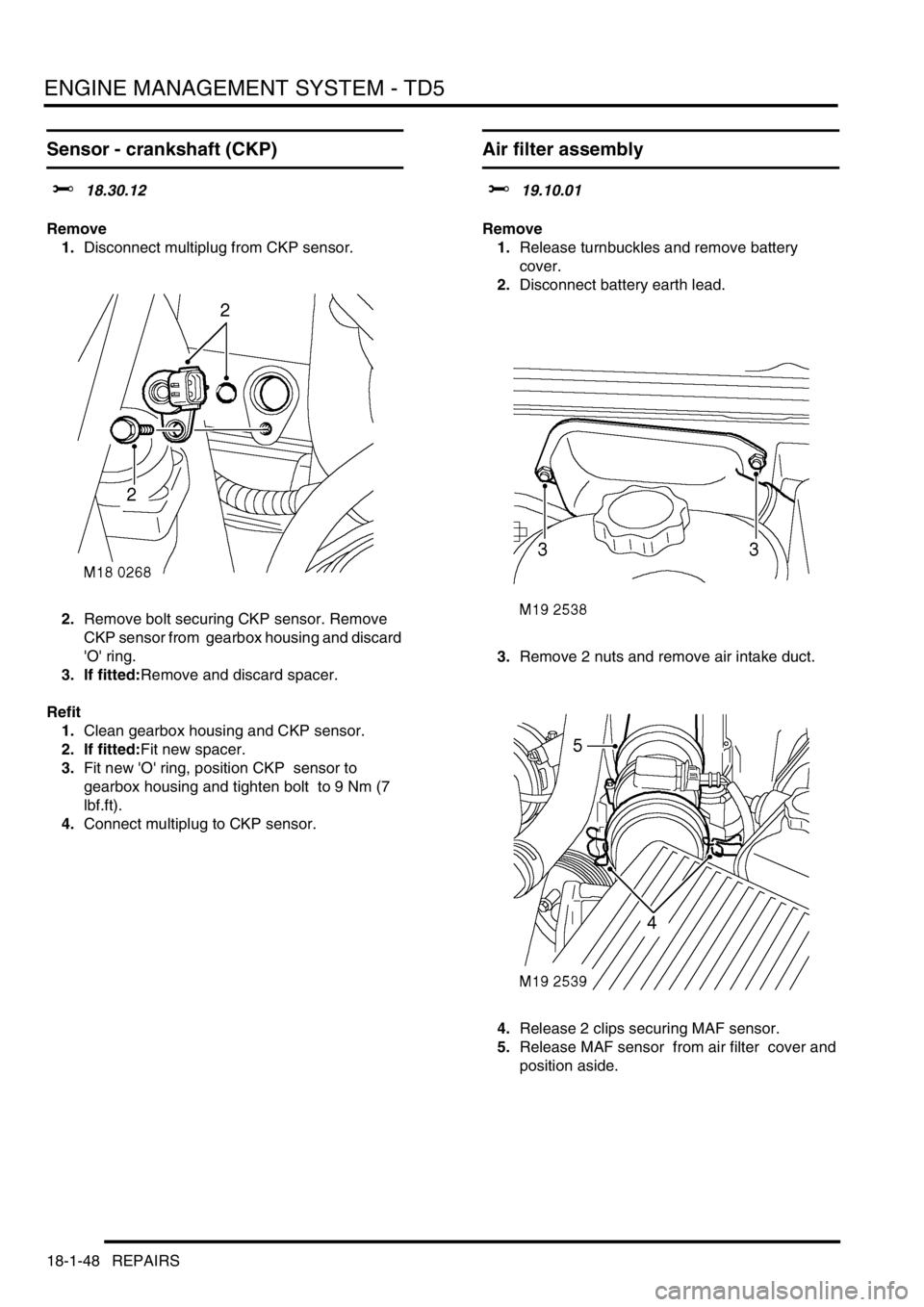
1.Disconnect multiplug from CKP sensor.
2.Remove bolt securing CKP sensor. Remove
CKP sensor from gearbox housing and discard
'O' ring.
3. If fitted:Remove and discard spacer.
Refit
1.Clean gearbox housing and CKP sensor.
2. If fitted:Fit new spacer.
3.Fit new 'O' ring, position CKP sensor to
gearbox housing and tighten bolt to 9 Nm (7
lbf.ft).
4.Connect multiplug to CKP sensor.
Air filter assembly
$% 19.10.01
Remove
1.Release turnbuckles and remove battery
cover.
2.Disconnect battery earth lead.
3.Remove 2 nuts and remove air intake duct.
4.Release 2 clips securing MAF sensor.
5.Release MAF sensor from air filter cover and
position aside.