gearbox LAND ROVER DISCOVERY 2002 Owner's Guide
[x] Cancel search | Manufacturer: LAND ROVER, Model Year: 2002, Model line: DISCOVERY, Model: LAND ROVER DISCOVERY 2002Pages: 1672, PDF Size: 46.1 MB
Page 188 of 1672

ENGINE - TD5
REPAIRS 12-1-49
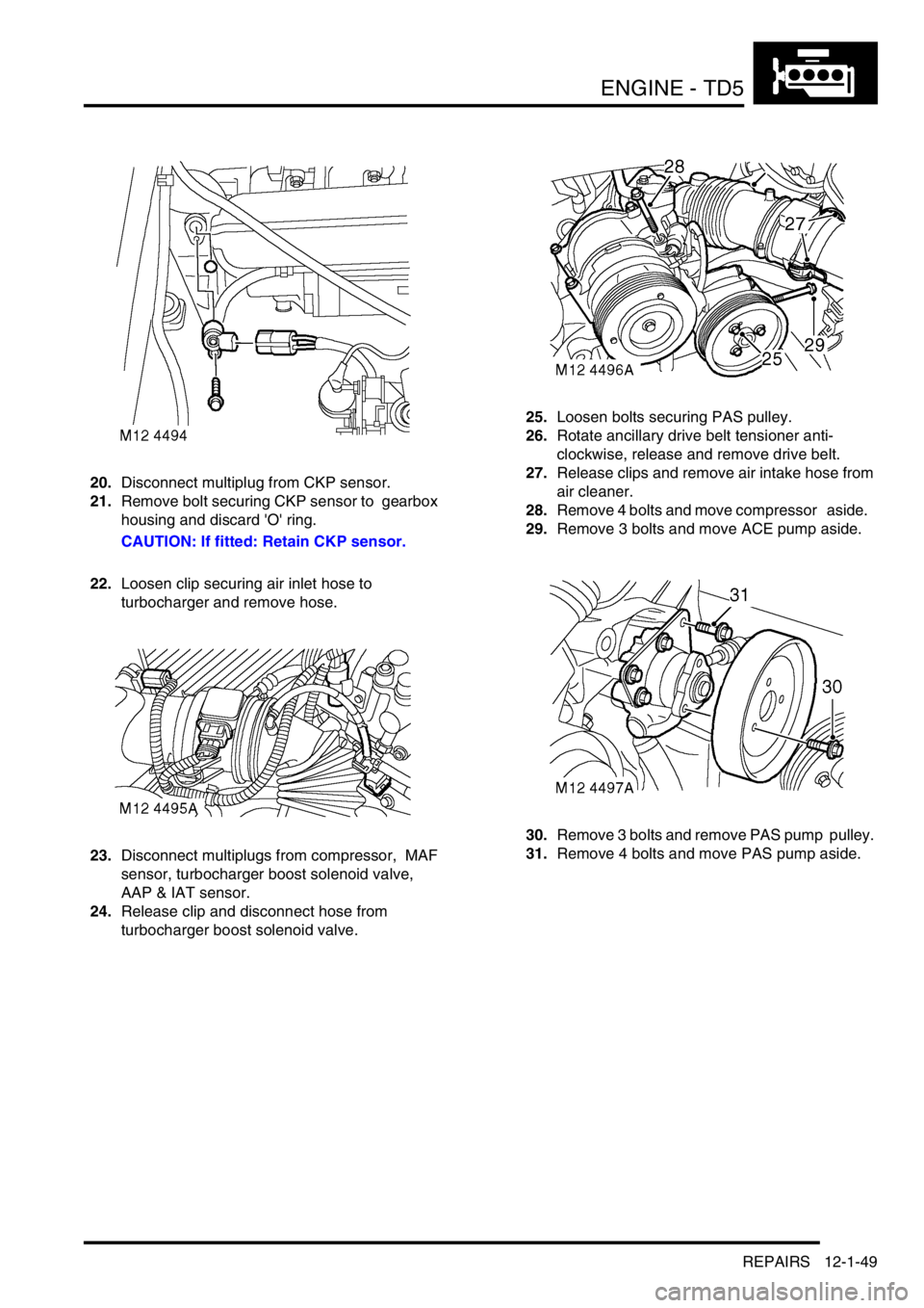
20.Disconnect multiplug from CKP sensor.
21.Remove bolt securing CKP sensor to gearbox
housing and discard 'O' ring.
CAUTION: If fitted: Retain CKP sensor.
22.Loosen clip securing air inlet hose to
turbocharger and remove hose.
23.Disconnect multiplugs from compressor, MAF
sensor, turbocharger boost solenoid valve,
AAP & IAT sensor.
24.Release clip and disconnect hose from
turbocharger boost solenoid valve. 25.Loosen bolts securing PAS pulley.
26.Rotate ancillary drive belt tensioner anti-
clockwise, release and remove drive belt.
27.Release clips and remove air intake hose from
air cleaner.
28.Remove 4 bolts and move compressor aside.
29.Remove 3 bolts and move ACE pump aside.
30.Remove 3 bolts and remove PAS pump pulley.
31.Remove 4 bolts and move PAS pump aside.
Page 189 of 1672

ENGINE - TD5
12-1-50 REPAIRS
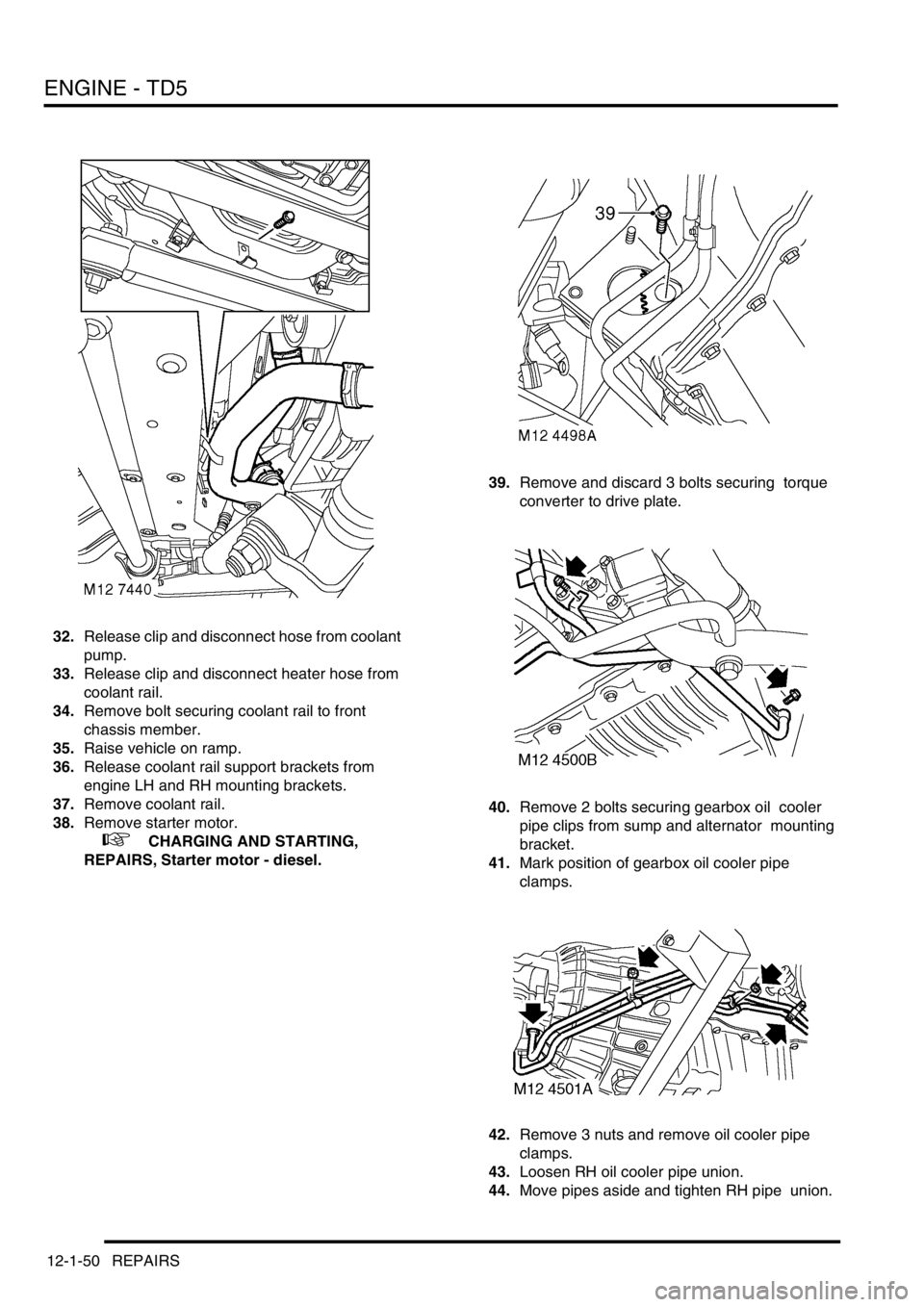
32.Release clip and disconnect hose from coolant
pump.
33.Release clip and disconnect heater hose from
coolant rail.
34.Remove bolt securing coolant rail to front
chassis member.
35.Raise vehicle on ramp.
36.Release coolant rail support brackets from
engine LH and RH mounting brackets.
37.Remove coolant rail.
38.Remove starter motor.
+ CHARGING AND STARTING,
REPAIRS, Starter motor - diesel.39.Remove and discard 3 bolts securing torque
converter to drive plate.
40.Remove 2 bolts securing gearbox oil cooler
pipe clips from sump and alternator mounting
bracket.
41.Mark position of gearbox oil cooler pipe
clamps.
42.Remove 3 nuts and remove oil cooler pipe
clamps.
43.Loosen RH oil cooler pipe union.
44.Move pipes aside and tighten RH pipe union.
Page 190 of 1672

ENGINE - TD5
REPAIRS 12-1-51
45.Remove 8 bolts and remove front cross
member.
46.Remove 6 bolts securing gearbox housing to
engine.
47.Remove 4 bolts and nuts securing RH and LH
front engine mountings to chassis.
48.Lower vehicle ramp. 49.Remove 2 upper bolts securing gearbox
housing and oil cooler coolant pipe to engine.
50.Release clip, disconnect hose from engine oil
cooler and move aside.
51.Remove bolt securing engine closing panel to
gearbox.
52.Fit tool LRT-12-138 to lifting chains and
connect to lifting eyes on engine.
53.Remove 2 nuts from RH and LH front engine
mountings.
54.Position trolley jack to support gearbox.
55.With assistance, raise chains, remove engine
from vehicle and lower onto bench.
Refit
1.With assistance, raise engine from bench and
position in vehicle.
2.With assistance, align engine to gearbox and
torque converter.
3.Position engine RH and LH mountings to
brackets and fit nuts.
4.Position engine oil cooler pipe, connect hose to
oil cooler and secure with clip.
Page 191 of 1672

ENGINE - TD5
12-1-52 REPAIRS
5.Fit 2 upper bolts securing engine oil cooler pipe
and gearbox housing to engine and tighten to
50 Nm (37 lbf.ft) .
6.Lower engine onto mountings, and tighten nuts
to 85 Nm (63 lbf.ft) .
7.Remove tool LRT-12-138 from engine.
8.Fit and tighten bolt securing engine closing
panel to gearbox.
9.Raise vehicle on ramp.
10.Fit nuts and bolts securing engine LH and RH
mountings to chassis and tighten to 85 Nm (63
lbf.ft).
11.Fit remaining bolts securing gearbox housing to
engine and tighten to 50 Nm (37 lbf.ft).
12.Rotate crankshaft and align drive plate to
torque converter.
13.Using a magnetic socket, fit and tighten new
torque converter drive plate bolts to 50 Nm (37
lbf.ft) .
14.Fit front cross member and tighten bolts to 26
Nm (19 lbf.ft).
15.Align gearbox oil cooler pipes.
16.Fit oil cooler pipe clip and tighten bolts to 9 Nm
(7 lbf.ft).
17.Position gearbox oil cooler pipe clamps and
tighten nuts.
18.Position coolant rail and secure support bracket
in engine LH and RH mounting brackets.
19.Fit starter motor.
+ CHARGING AND STARTING,
REPAIRS, Starter motor - diesel.
20.Lower ramp.
21.Position coolant rail to front chassis member, fit
and tighten bolt to 10 Nm (7 lbf.ft).
22.Connect heater hose to coolant rail and secure
with clip.
23.Connect hose to coolant pump and secure with
clip.
24.Position PAS pump and tighten bolts to 25 Nm
(18 lbf.ft).
25.Position PAS pump pulley and lightly tighten
bolts.
26.Position ACE pump, fit bolts and tighten to 25
Nm (18 lbf.ft).
27.Position A/C compressor, fit bolts and tighten
to 25 Nm (18 lbf.ft).
28.Position ancillary drive belt, rotate tensioner
anti-clockwise and locate belt to pulleys.
29.Tighten PAS pump pulley bolts to 10 Nm (7
lbf.ft).
30.Position air intake hose to air cleaner and
secure clips.
31.Position engine harness and connect
multiplugs to compressor, MAF sensor,
turbocharger boost solenoid, AAP & IAT
sensor.
32.Position air inlet hose to turbocharger and
tighten clip. 33.Connect hoses to turbocharger boost solenoid
and secure clips.
34.Clean CKP sensor and mating face.
CAUTION: If originally fitted: Fit spacer to
CKP sensor.
35.Using new 'O' ring, fit CKP sensor, tighten CKP
sensor bolt to 9 Nm (7 lbf.ft) and connect
multiplug.
36.Connect multiplug to EGR modulator.
37.Connect engine earth lead to battery earth lead
and tighten bolt.
38.Connect engine harness multiplug to ECM and
main harness.
39.Connect engine harness multiplugs to fuse
box.
40.Position glow plug lead to fusebox and secure
with bolt.
41.Position battery and alternator leads to fusebox
and secure with bolts.
42.Fit engine compartment fuse box cover.
43.Connect vacuum hose to EGR valve.
44.Connect hose to vacuum pump and secure
vacuum pipe to fuel cooler.
45.Disconnect fuel hose from connector block and
connect to fuel cooler.
46.Connect fuel hoses to fuel cooler and
connector block on cylinder head.
47.Position expansion tank, connect hose and
secure with clip. Secure tank to body mounting.
48.Connect coolant hoses to fuel cooler and
coolant rail and secure clips.
49.Fit turbocharger.
+ ENGINE MANAGEMENT SYSTEM -
Td5, REPAIRS, Turbocharger.
50. Fit radiator.
+ COOLING SYSTEM - Td5, REPAIRS,
Radiator.
51.Fill engine with oil.
+ MAINTENANCE, PROCEDURES,
Engine oil - diesel engine.
52.Fit underbelly panel.
+ EXTERIOR FITTINGS, REPAIRS,
Panel - underbelly.
53.Fit bonnet.
+ EXTERIOR FITTINGS, REPAIRS,
Bonnet.
Page 194 of 1672

ENGINE - TD5
REPAIRS 12-1-55
Mounting - engine - rear - LH
$% 12.45.07
Remove
1.Raise vehicle on ramp.
2.Position jack to support gearbox.
3.Remove 2 nuts and remove mounting.
4.Remove heat shield from mounting.
Refit
1.Clean mounting and mating faces.
2.Position heat shield to mounting.
3.Position engine rear LH mounting and tighten
nuts to 48 Nm (35 lbf.ft).
4.Lower support jack.
5.Lower vehicle.
Mounting - engine - rear - RH
$% 12.45.09
Remove
1.Raise vehicle on ramp.
2.Position jack to support gearbox.
3.Remove 2 nuts and remove mounting.
Refit
1.Clean mounting and mating faces.
2.Position engine rear RH mounting and tighten
nuts to 48 Nm (35 lbf.ft).
3.Lower support jack.
4.Lower vehicle.
Page 195 of 1672

ENGINE - TD5
12-1-56 REPAIRS
Flywheel
$% 12.53.07
Remove
1.Remove clutch assembly.
+ CLUTCH - Td5, REPAIRS, Clutch
assembly.
2.Remove and discard 8 bolts securing flywheel
to crankshaft and remove flywheel.
Refit
1.Clean flywheel and mating face.
2.Position flywheel to crankshaft, fit new bolts
and working in a diagonal sequence tighten to
40 Nm (30 lbf.ft), then a further 90
°.
CAUTION: Do not carry out stages 1 and 2 in
one operation.
3.Fit clutch assembly.
+ CLUTCH - Td5, REPAIRS, Clutch
assembly.
Plate - drive - automatic
$% 12.53.13
Remove
1.Remove gearbox.
+ AUTOMATIC GEARBOX - ZF4HP22
- 24, REPAIRS, Gearbox - convertor and
transfer gearbox - Diesel.
2.Remove and discard 8 bolts and remove
converter drive plate, spacer and starter ring
gear.
Refit
1.Clean drive plate, spacer and starter ring gear.
2.Fit starter ring gear, spacer and drive plate to
crankshaft, fit new bolts and working in a
diagonal sequence tighten to 40 Nm (30 lbf.ft),
then a further 90
°.
CAUTION: Do not carry out stages 1 and 2 in
one operation.
3.Refit gearbox.
+ AUTOMATIC GEARBOX - ZF4HP22
- 24, REPAIRS, Gearbox - convertor and
transfer gearbox - Diesel.
Page 199 of 1672

ENGINE - TD5
12-1-60 REPAIRS
Gasket - sump
$% 12.60.38
Remove
1.Remove battery cover.
2.Disconnect battery earth lead.
3.Remove exhaust front pipe.
+ MANIFOLDS AND EXHAUST
SYSTEMS - Td5, REPAIRS, Pipe - front.
4.Drain engine oil.
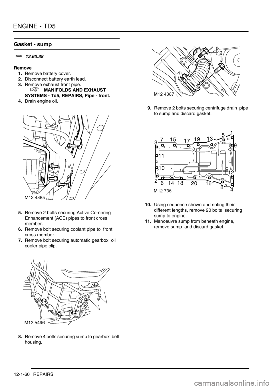
5.Remove 2 bolts securing Active Cornering
Enhancement (ACE) pipes to front cross
member.
6.Remove bolt securing coolant pipe to front
cross member.
7.Remove bolt securing automatic gearbox oil
cooler pipe clip.
8.Remove 4 bolts securing sump to gearbox bell
housing. 9.Remove 2 bolts securing centrifuge drain pipe
to sump and discard gasket.
10.Using sequence shown and noting their
different lengths, remove 20 bolts securing
sump to engine.
11.Manoeuvre sump from beneath engine,
remove sump and discard gasket.
Page 200 of 1672

ENGINE - TD5
REPAIRS 12-1-61
Refit
1.Clean sump and mating faces.
2.Apply sealant, Part No. STC 3254 to joint faces
of timing chain cover and crankshaft rear oil
seal housing.
CAUTION: Assembly and bolt tightening
must be completed within 20 minutes of
applying sealant.
3.Position new gasket.
CAUTION: Gasket must be fitted dry.
4.Position sump and, noting the positions of the
longer bolts, fit and lightly tighten bolts.
5.Fit and lightly tighten bolts securing sump to
gearbox bell housing. 6.Working in the sequence shown, tighten bolts
securing sump to 25 Nm (18 lbf.ft).
7.Tighten – sump to gearbox bell housing bolts
to 13 Nm (10 lbf.ft).
8.Fit new gasket to centrifuge drain pipe, fit to
sump and tighten bolts to 10 Nm (7 lbf.ft ) .
CAUTION: Gasket must be fitted dry.
9.Fit bolts securing oil cooler pipe to sump and
tighten to 9 Nm (7 lbf.ft).
10.Fit and tighten bolt securing coolant pipe to
cross member.
11.Fit and tighten bolts securing ACE pipes to front
cross member.
12.Fit exhaust front pipe.
+ MANIFOLDS AND EXHAUST
SYSTEMS - Td5, REPAIRS, Pipe - front.
13.Refill engine with oil.
14.Connect battery earth lead.
15.Refit battery cover and secure fixings.
Page 256 of 1672

ENGINE - V8
REPAIRS 12-2-13
REPAIRS
Seal - crankshaft - rear
$% 12.21.20
Remove
1. Automatic gearbox models:Remove
converter drive plate.
+ ENGINE - V8, REPAIRS, Plate - drive
- automatic.
2. Manual gearbox models:Remove flywheel.
+ ENGINE - V8, REPAIRS, Flywheel.
3.Carefully remove oil seal from cylinder block to
avoid damage to seal location or running
surface on crankshaft. Discard seal.
Refit
1.Ensure both seal location and running surface
on crankshaft are clean. 2.Fit seal guide LRT-12-095 to crankshaft.
CAUTION: Oil seal must be fitted dry.
3.Fit new oil seal squarely onto crankshaft and
remove guide.
4.Fit seal into location using tools LRT-12-091
and LRT-99-003.
5. Automatic gearbox models:Fit converter
drive plate.
+ ENGINE - V8, REPAIRS, Plate - drive
- automatic.
6. Manual gearbox models:Fit flywheel.
+ ENGINE - V8, REPAIRS, Flywheel.
Page 267 of 1672

ENGINE - V8
12-2-24 REPAIRS
Mounting - rear - LH
$% 12.45.07
Remove
1.Raise vehicle on lift.
2.Remove 8 bolts securing rear cross member
and remove cross member.
3.Support transfer gearbox on jack.
CAUTION: To prevent damage to
components, cushion the jack pad with a
block of wood or hard rubber.
4.Release and disconnect HO2S multiplug.5.Remove nut securing mounting to body
bracket.
6.Remove nut securing mounting to mounting
bracket.
7.Remove 4 bolts securing mounting bracket to
gearbox.
8.Remove mounting and mounting bracket
assembly.
9.Remove mounting rubber.
10.Remove heat shield, if fitted.
Refit
1.If fitted position heatshield, fit mounting rubber
to mounting bracket, fit nut but do not tighten.
2.Position mounting bracket assembly, fit bolts
securing mounting bracket to gearbox and
tighten to 85 Nm (63 lbf.ft).
3.Fit nut securing mounting to body bracket and
tighten to 48 Nm (35 lbf.ft).
4.Tighten nut securing mounting to gearbox
bracket to 48 Nm (35 lbf.ft).
5.Connect HO2S multiplug and secure to support
bracket.
6.Position rear cross member, fit bolts and
tighten to 26 Nm (19 lbf.ft).
7.Lower vehicle.