battery replacement LAND ROVER DISCOVERY 2002 Workshop Manual
[x] Cancel search | Manufacturer: LAND ROVER, Model Year: 2002, Model line: DISCOVERY, Model: LAND ROVER DISCOVERY 2002Pages: 1672, PDF Size: 46.1 MB
Page 58 of 1672
GENERAL INFORMATION
03-23
Airbag and pretensioner deployment
Deployment procedures and precautions as detailed
in this manual should be strictly adhered to. Only
personnel who have undergone the appropriate
training should undertake deployment of airbag and
pretensioner modules. The following precautions
must be complied with:
lOnly use deployment equipment approved for
the intended purpose.
lBefore beginning deployment procedure,
ensure deployment tool functions properly by
performing the self test procedure detailed in
SRS section of this manual.
lDeployment of airbag/ pretensioner modules
should be performed in a well ventilated area
which has been designated for the purpose.
lEnsure airbag/pretensioner modules are not
damaged or ruptured before attempting to
deploy.
lNotify the relevant authorities of intention to
deploy airbag and pretensioner units.
lWhen deploying airbag pretensioner units,
ensure that all personnel are at least 15 metres
(45 feet) away from the deployment zone.
lEnsure deployment tool is connected correctly,
in compliance with the instructions detailed in
the SRS section of this manual. In particular,
ensure deployment tool is NOT connected to
battery supply before connecting to airbag
module connector.
lWhen deploying seat belt pretensioners, ensure
pretensioner unit is secured correctly to the
seat.
lWhen removing deployed airbag modules and
pretensioner units, wear protective clothing.
Use gloves and seal deployed units in a plastic
bag.
lFollowing deployment of any component of the
SRS system within the vehicle, all SRS
components must be replaced. DO NOT re-use
or salvage any parts of the SRS system.
lDo not lean over airbag module when
connecting deployment equipment.
If a vehicle is to be scrapped, undeployed airbag
modules and pretensioner units must be manually
deployed. In this case airbags can be deployed in the
vehicle; before deployment, ensure the airbag
module is secure within its correct mounting position.
Deployment of the driver's airbag in the vehicle may
damage the steering wheel; if the vehicle is not being
scrapped, deploy the module outside of the vehicle.
WARNING: During deployment parts of the
airbag module become hot enough to burn you.
Wait 30 minutes after deployment before
touching the airbag module.
SRS Component Replacement Policy
The following information details the policy for
replacement of SRS components; either as a result
of a vehicle accident or as a result of vehicle age.
Impacts which do not deploy the airbags or pre-
tensioners
Check for structural damage in the area of the
impact, paying particular attention to bumper
armatures, longitudinals, crash cans and bracketry.
Impacts which deploy the airbags or pre-
tensioners
The replacement and inspection policy is dependent
on the type and severity of of the crash condition.
The following guidelines are the minimum that
should be exercised as a result of the deployment of
specific SRS components.
If the front airbags or seat belt pre-tensioners are
deployed, the following parts must be replaced:
lSRS DCU.
lDriver airbag module
lPassenger airbag module
lFront seat belt buckle pre-tensioners
lRotary coupler
lDriver's seat belt retractor
lFlyleads (where applicable) connecting airbags
and seat belt pre-tensioners to SRS harness
In addition, the following should be inspected for
damage and replaced as necessary:
lFront passenger's seat belt retractor (webbing,
tongue latching, 'D' loop, body anchorage point)
lRear seat belt buckles (webbing, buckle covers,
body anchorage and tongue latching function)
lFascia moulding adjacent to passenger airbag
module
lSteering wheel (if damage is evident)
lFront seat frames and head restraints (if there is
evidence of damage to the seat frame or
cushion pan)
lSteering column (if adjustment is lost or there
are signs of collapse)
lThird row seats, seat belts and head restraints
(where fitted). Check third row seat latching
mechanism operates correctly.
Periodic replacement of SRS components
The performance of the propellants within airbags
and pre-tensioners will deteriorate over a period of
time. As a result, it is essential that the airbags are
replaced after 10 years and seat belt pre-tensioners
are replaced after 15 years in order to maintain
occupant safety.
Page 115 of 1672
MAINTENANCE
10-6 PROCEDURES
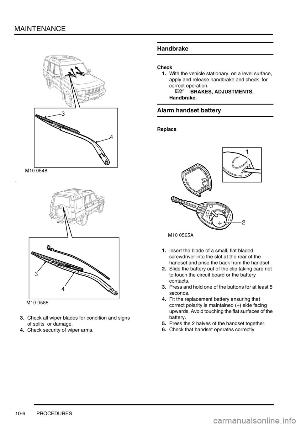
3.Check all wiper blades for condition and signs
of splits or damage.
4.Check security of wiper arms.
Handbrake
Check
1.With the vehicle stationary, on a level surface,
apply and release handbrake and check for
correct operation.
+ BRAKES, ADJUSTMENTS,
Handbrake.
Alarm handset battery
Replace
1.Insert the blade of a small, flat bladed
screwdriver into the slot at the rear of the
handset and prise the back from the handset.
2.Slide the battery out of the clip taking care not
to touch the circuit board or the battery
contacts.
3.Press and hold one of the buttons for at least 5
seconds.
4.Fit the replacement battery ensuring that
correct polarity is maintained (+) side facing
upwards. Avoid touching the flat surfaces of the
battery.
5.Press the 2 halves of the handset together.
6.Check that handset operates correctly.
Page 124 of 1672

MAINTENANCE
PROCEDURES 10-15
Centrifuge rotor – diesel engine
Replace
1.Replace centrifuge rotor.
+ ENGINE - Td5, REPAIRS, Rotor -
centrifuge.
Engine oil filter - diesel engine
Replace
1.Replace oil filter.
+ ENGINE - Td5, REPAIRS, Filter - oil.
Engine oil filter – V8 engine
WARNING: Avoid excessive skin contact with
used engine oil. Used engine oil contains
potentially harmful contaminants which may
cause skin cancer or other serious skin
disorders.
Replace
1.Disconnect battery.
2.Position suitable container beneath oil filter.
3.Using a strap type filter wrench, remove filter
element, discard element.
4.Smear sealing ring of replacement filter
element with engine oil.
5.Fit filter element, tighten two thirds of a turn by
hand or to 17 Nm (13 lbf.ft).
6.Top-up engine with recommended grade of oil
to correct mark on dipstick.
+ CAPACITIES, FLUIDS AND
LUBRICANTS, Lubrication.
7.Connect battery.
8.Run engine and check for oil leaks from filter.
9.Stop engine, wait for oil to return to sump.
10.Re-check oil level and top-up if necessary.
Page 440 of 1672
ENGINE MANAGEMENT SYSTEM - TD5
REPAIRS 18-1-47
REPAIRS
Engine control module (ECM)
$% 18.30.03
All replacement ECM's are configured for two track
TP sensors. When fitting replacement ECM to
vehicle with three track TP sensor, TestBook must be
used to configure ECM for three track TP sensor.
Remove
1.Release fixings and remove battery cover.
2.Disconnect battery earth lead.
3.Release retaining strap and remove vehicle
jack.
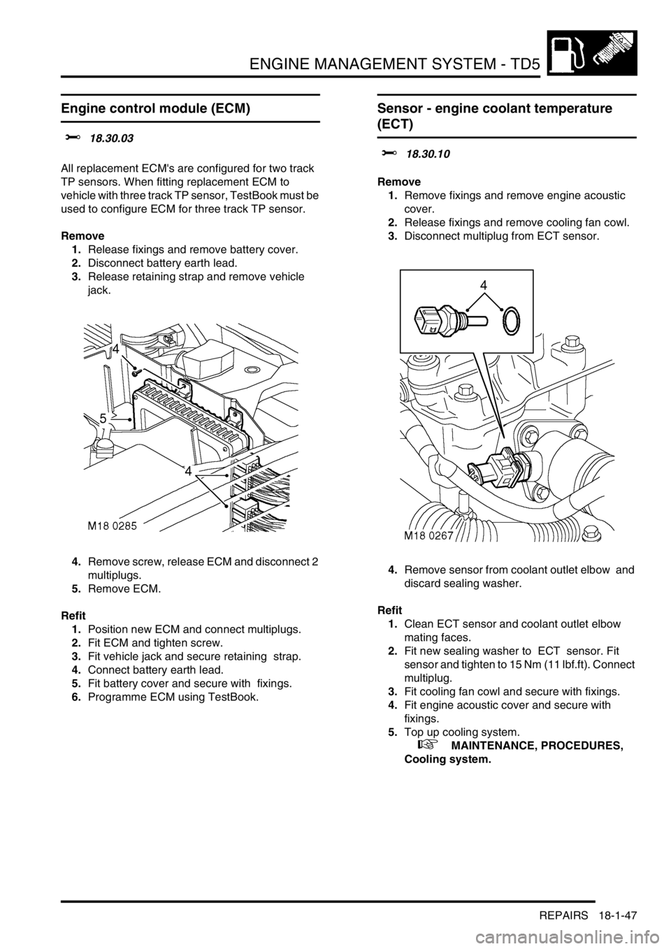
4.Remove screw, release ECM and disconnect 2
multiplugs.
5.Remove ECM.
Refit
1.Position new ECM and connect multiplugs.
2.Fit ECM and tighten screw.
3.Fit vehicle jack and secure retaining strap.
4.Connect battery earth lead.
5.Fit battery cover and secure with fixings.
6.Programme ECM using TestBook.
Sensor - engine coolant temperature
(ECT)
$% 18.30.10
Remove
1.Remove fixings and remove engine acoustic
cover.
2.Release fixings and remove cooling fan cowl.
3.Disconnect multiplug from ECT sensor.
4.Remove sensor from coolant outlet elbow and
discard sealing washer.
Refit
1.Clean ECT sensor and coolant outlet elbow
mating faces.
2.Fit new sealing washer to ECT sensor. Fit
sensor and tighten to 15 Nm (11 lbf.ft). Connect
multiplug.
3.Fit cooling fan cowl and secure with fixings.
4.Fit engine acoustic cover and secure with
fixings.
5.Top up cooling system.
+ MAINTENANCE, PROCEDURES,
Cooling system.
Page 464 of 1672
ENGINE MANAGEMENT SYSTEM - V8
DESCRIPTION AND OPERATION 18-2-7
The ECM controls the following outputs:
lFuel injectors (1 per cylinder).
lIgnition coils/ high tension leads/ spark plugs.
lFuel pump relay.
lIdle air control valve.
lHeated oxygen sensors.
lEVAP canister purge valve.
lEVAP canister vent solenoid (CVS) valve (where fitted).
lMalfunction Indicator Lamp (MIL)/ service engine soon lamp (where fitted).
lHill descent control (via SLABS interface).
lEVAP system fuel leak detection pump (where fitted)
lSecondary air injection pump (where fitted)
The ECM also interfaces with the following:
lDiagnostics via diagnostic connector with TestBook.
lController Area Network (CAN) link to EAT ECU.
lAir conditioning system.
lSelf Levelling & Anti-lock Braking System (SLABS) ECU.
lImmobilisation system via the body control unit (BCU).
lInstrument cluster.
lCruise control ECU
lActive Cornering Enhancement (ACE) ECU
Engine Control Module (ECM)
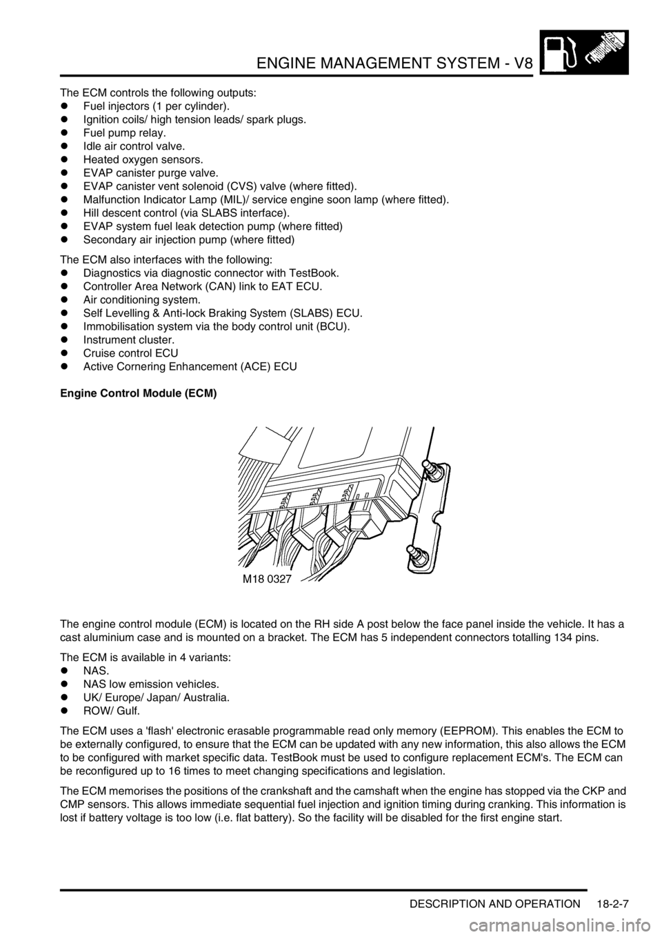
The engine control module (ECM) is located on the RH side A post below the face panel inside the vehicle. It has a
cast aluminium case and is mounted on a bracket. The ECM has 5 independent connectors totalling 134 pins.
The ECM is available in 4 variants:
lNAS.
lNAS low emission vehicles.
lUK/ Europe/ Japan/ Australia.
lROW/ Gulf.
The ECM uses a 'flash' electronic erasable programmable read only memory (EEPROM). This enables the ECM to
be externally configured, to ensure that the ECM can be updated with any new information, this also allows the ECM
to be configured with market specific data. TestBook must be used to configure replacement ECM's. The ECM can
be reconfigured up to 16 times to meet changing specifications and legislation.
The ECM memorises the positions of the crankshaft and the camshaft when the engine has stopped via the CKP and
CMP sensors. This allows immediate sequential fuel injection and ignition timing during cranking. This information is
lost if battery voltage is too low (i.e. flat battery). So the facility will be disabled for the first engine start.
Page 1270 of 1672
PANEL REPAIRS
REPAIRS 77-2-21
REPAIRS
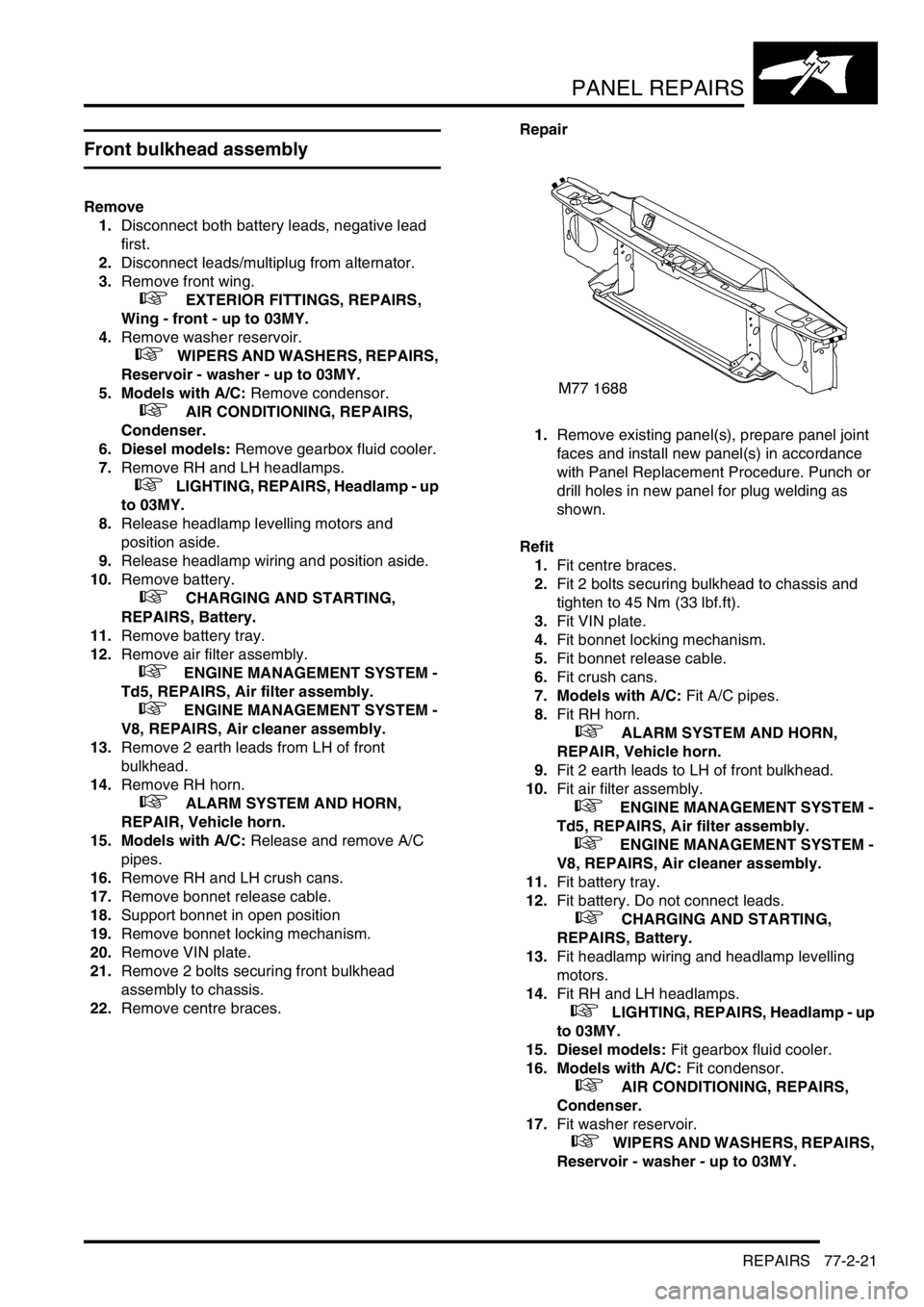
Front bulkhead assembly
Remove
1.Disconnect both battery leads, negative lead
first.
2.Disconnect leads/multiplug from alternator.
3.Remove front wing.
+ EXTERIOR FITTINGS, REPAIRS,
Wing - front - up to 03MY.
4.Remove washer reservoir.
+ WIPERS AND WASHERS, REPAIRS,
Reservoir - washer - up to 03MY.
5. Models with A/C: Remove condensor.
+ AIR CONDITIONING, REPAIRS,
Condenser.
6. Diesel models: Remove gearbox fluid cooler.
7.Remove RH and LH headlamps.
+ LIGHTING, REPAIRS, Headlamp - up
to 03MY.
8.Release headlamp levelling motors and
position aside.
9.Release headlamp wiring and position aside.
10.Remove battery.
+ CHARGING AND STARTING,
REPAIRS, Battery.
11.Remove battery tray.
12.Remove air filter assembly.
+ ENGINE MANAGEMENT SYSTEM -
Td5, REPAIRS, Air filter assembly.
+ ENGINE MANAGEMENT SYSTEM -
V8, REPAIRS, Air cleaner assembly.
13.Remove 2 earth leads from LH of front
bulkhead.
14.Remove RH horn.
+ ALARM SYSTEM AND HORN,
REPAIR, Vehicle horn.
15. Models with A/C: Release and remove A/C
pipes.
16.Remove RH and LH crush cans.
17.Remove bonnet release cable.
18.Support bonnet in open position
19.Remove bonnet locking mechanism.
20.Remove VIN plate.
21.Remove 2 bolts securing front bulkhead
assembly to chassis.
22.Remove centre braces.Repair
1.Remove existing panel(s), prepare panel joint
faces and install new panel(s) in accordance
with Panel Replacement Procedure. Punch or
drill holes in new panel for plug welding as
shown.
Refit
1.Fit centre braces.
2.Fit 2 bolts securing bulkhead to chassis and
tighten to 45 Nm (33 lbf.ft).
3.Fit VIN plate.
4.Fit bonnet locking mechanism.
5.Fit bonnet release cable.
6.Fit crush cans.
7. Models with A/C: Fit A/C pipes.
8.Fit RH horn.
+ ALARM SYSTEM AND HORN,
REPAIR, Vehicle horn.
9.Fit 2 earth leads to LH of front bulkhead.
10.Fit air filter assembly.
+ ENGINE MANAGEMENT SYSTEM -
Td5, REPAIRS, Air filter assembly.
+ ENGINE MANAGEMENT SYSTEM -
V8, REPAIRS, Air cleaner assembly.
11.Fit battery tray.
12.Fit battery. Do not connect leads.
+ CHARGING AND STARTING,
REPAIRS, Battery.
13.Fit headlamp wiring and headlamp levelling
motors.
14.Fit RH and LH headlamps.
+ LIGHTING, REPAIRS, Headlamp - up
to 03MY.
15. Diesel models: Fit gearbox fluid cooler.
16. Models with A/C: Fit condensor.
+ AIR CONDITIONING, REPAIRS,
Condenser.
17.Fit washer reservoir.
+ WIPERS AND WASHERS, REPAIRS,
Reservoir - washer - up to 03MY.
Page 1272 of 1672
PANEL REPAIRS
REPAIRS 77-2-23
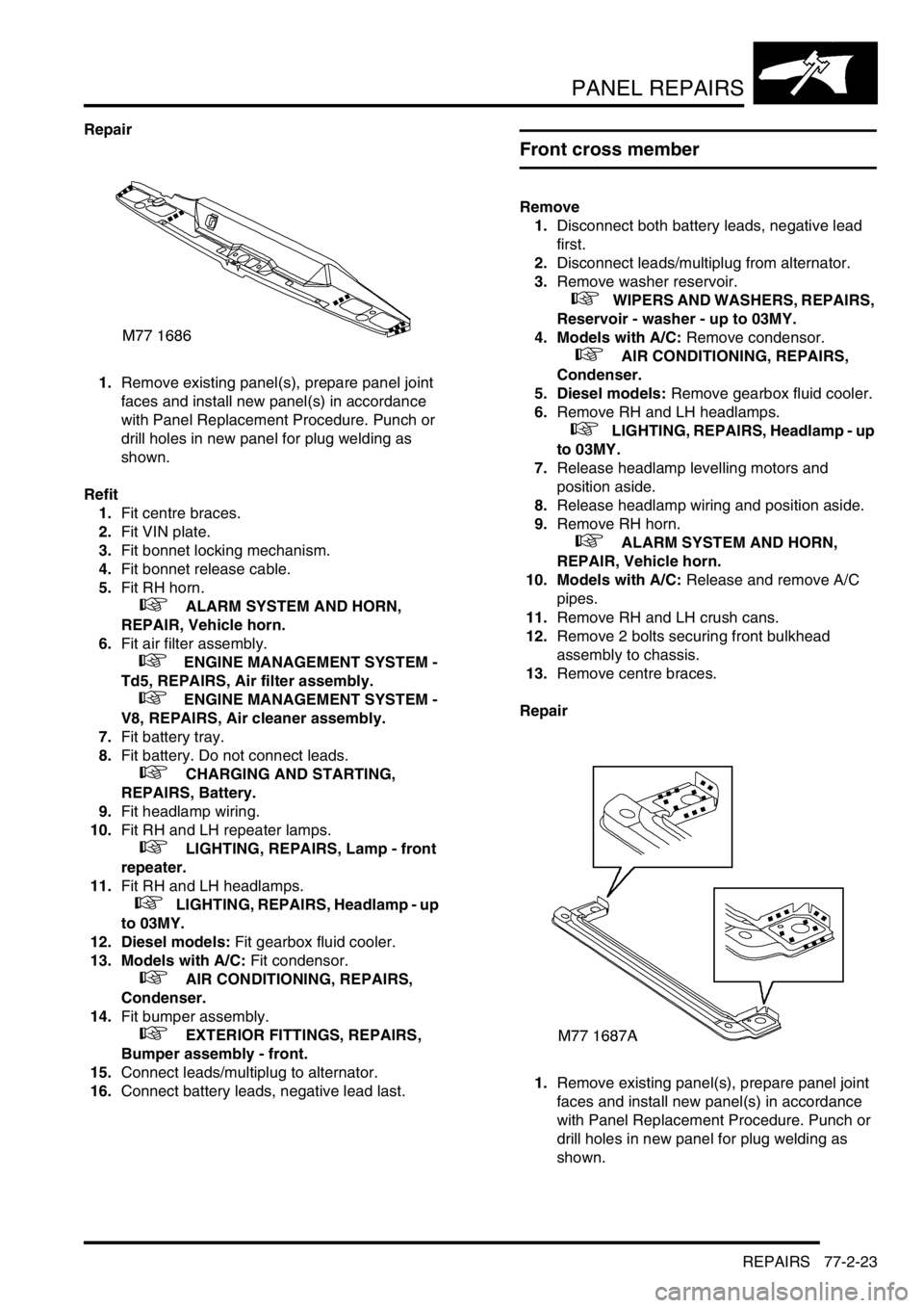
Repair
1.Remove existing panel(s), prepare panel joint
faces and install new panel(s) in accordance
with Panel Replacement Procedure. Punch or
drill holes in new panel for plug welding as
shown.
Refit
1.Fit centre braces.
2.Fit VIN plate.
3.Fit bonnet locking mechanism.
4.Fit bonnet release cable.
5.Fit RH horn.
+ ALARM SYSTEM AND HORN,
REPAIR, Vehicle horn.
6.Fit air filter assembly.
+ ENGINE MANAGEMENT SYSTEM -
Td5, REPAIRS, Air filter assembly.
+ ENGINE MANAGEMENT SYSTEM -
V8, REPAIRS, Air cleaner assembly.
7.Fit battery tray.
8.Fit battery. Do not connect leads.
+ CHARGING AND STARTING,
REPAIRS, Battery.
9.Fit headlamp wiring.
10.Fit RH and LH repeater lamps.
+ LIGHTING, REPAIRS, Lamp - front
repeater.
11.Fit RH and LH headlamps.
+ LIGHTING, REPAIRS, Headlamp - up
to 03MY.
12. Diesel models: Fit gearbox fluid cooler.
13. Models with A/C: Fit condensor.
+ AIR CONDITIONING, REPAIRS,
Condenser.
14.Fit bumper assembly.
+ EXTERIOR FITTINGS, REPAIRS,
Bumper assembly - front.
15.Connect leads/multiplug to alternator.
16.Connect battery leads, negative lead last.
Front cross member
Remove
1.Disconnect both battery leads, negative lead
first.
2.Disconnect leads/multiplug from alternator.
3.Remove washer reservoir.
+ WIPERS AND WASHERS, REPAIRS,
Reservoir - washer - up to 03MY.
4. Models with A/C: Remove condensor.
+ AIR CONDITIONING, REPAIRS,
Condenser.
5. Diesel models: Remove gearbox fluid cooler.
6.Remove RH and LH headlamps.
+ LIGHTING, REPAIRS, Headlamp - up
to 03MY.
7.Release headlamp levelling motors and
position aside.
8.Release headlamp wiring and position aside.
9.Remove RH horn.
+ ALARM SYSTEM AND HORN,
REPAIR, Vehicle horn.
10. Models with A/C: Release and remove A/C
pipes.
11.Remove RH and LH crush cans.
12.Remove 2 bolts securing front bulkhead
assembly to chassis.
13.Remove centre braces.
Repair
1.Remove existing panel(s), prepare panel joint
faces and install new panel(s) in accordance
with Panel Replacement Procedure. Punch or
drill holes in new panel for plug welding as
shown.
Page 1274 of 1672

PANEL REPAIRS
REPAIRS 77-2-25
Repair
1.Remove existing panel(s), prepare panel joint
faces and install new panel(s) in accordance
with Panel Replacement Procedure. Punch or
drill holes in new panel for plug welding as
shown.
Refit
1.Fit centre brace.
2.Fit 2 bolts securing bulkhead to chassis and
tighten bolts to 45 Nm (33 lbf.ft).
3.Fit crush can.
4. Models with A/C: Fit A/C pipes.
5.Fit horn.
+ ALARM SYSTEM AND HORN,
REPAIR, Vehicle horn.
6.Fit battery and battery tray. Do not connect
leads.
+ CHARGING AND STARTING,
REPAIRS, Battery.
7.Fit headlamp wiring and headlamp levelling
motors.
8.Fit repeater lamp.
+ LIGHTING, REPAIRS, Lamp - front
repeater.9.Fit headlamp.
+ LIGHTING, REPAIRS, Headlamp - up
to 03MY.
10. Diesel models: Fit gearbox fluid cooler.
11. Models with A/C: Fit condensor.
+ AIR CONDITIONING, REPAIRS,
Condenser.
12.Fit bumper assembly.
+ EXTERIOR FITTINGS, REPAIRS,
Bumper assembly - front.
13.Connect leads/multiplug to alternator.
14.Connect battery leads, negative lead last.
M77 1741A
Page 1275 of 1672
PANEL REPAIRS
77-2-26 REPAIRS
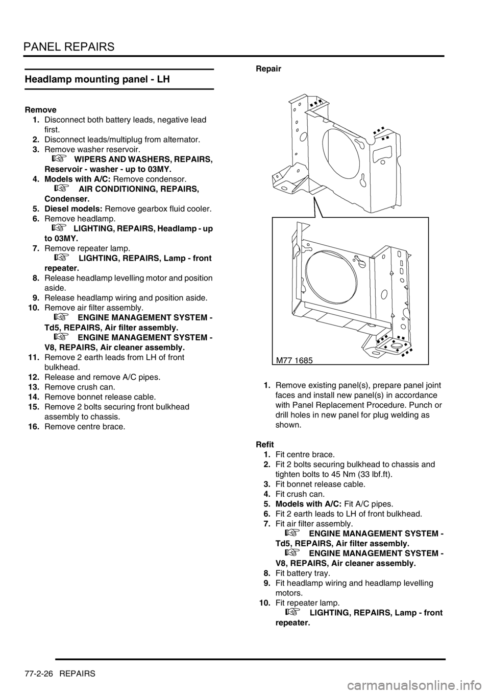
Headlamp mounting panel - LH
Remove
1.Disconnect both battery leads, negative lead
first.
2.Disconnect leads/multiplug from alternator.
3.Remove washer reservoir.
+ WIPERS AND WASHERS, REPAIRS,
Reservoir - washer - up to 03MY.
4. Models with A/C: Remove condensor.
+ AIR CONDITIONING, REPAIRS,
Condenser.
5. Diesel models: Remove gearbox fluid cooler.
6.Remove headlamp.
+ LIGHTING, REPAIRS, Headlamp - up
to 03MY.
7.Remove repeater lamp.
+ LIGHTING, REPAIRS, Lamp - front
repeater.
8.Release headlamp levelling motor and position
aside.
9.Release headlamp wiring and position aside.
10.Remove air filter assembly.
+ ENGINE MANAGEMENT SYSTEM -
Td5, REPAIRS, Air filter assembly.
+ ENGINE MANAGEMENT SYSTEM -
V8, REPAIRS, Air cleaner assembly.
11.Remove 2 earth leads from LH of front
bulkhead.
12.Release and remove A/C pipes.
13.Remove crush can.
14.Remove bonnet release cable.
15.Remove 2 bolts securing front bulkhead
assembly to chassis.
16.Remove centre brace.Repair
1.Remove existing panel(s), prepare panel joint
faces and install new panel(s) in accordance
with Panel Replacement Procedure. Punch or
drill holes in new panel for plug welding as
shown.
Refit
1.Fit centre brace.
2.Fit 2 bolts securing bulkhead to chassis and
tighten bolts to 45 Nm (33 lbf.ft).
3.Fit bonnet release cable.
4.Fit crush can.
5. Models with A/C: Fit A/C pipes.
6.Fit 2 earth leads to LH of front bulkhead.
7.Fit air filter assembly.
+ ENGINE MANAGEMENT SYSTEM -
Td5, REPAIRS, Air filter assembly.
+ ENGINE MANAGEMENT SYSTEM -
V8, REPAIRS, Air cleaner assembly.
8.Fit battery tray.
9.Fit headlamp wiring and headlamp levelling
motors.
10.Fit repeater lamp.
+ LIGHTING, REPAIRS, Lamp - front
repeater.
Page 1277 of 1672

PANEL REPAIRS
77-2-28 REPAIRS
Repair
1.Remove existing panel(s), prepare panel joint
faces and install new panel(s) in accordance
with Panel Replacement Procedure. Punch or
drill holes in new panel for plug welding as
shown.
Refit
1. Models with A/C: Fit A/C pipes and recharge
A/C system.
+ AIR CONDITIONING, REFRIGERANT
RECOVERY, RECYCLING AND
RECHARGING, Refrigerant recovery,
recycling and recharging.
2.Fit harness to valance.
3.Fit brake pipes to valance.
4.Fit ABS modulator.
+ BRAKES, REPAIRS, Modulator unit
- ABS.
5.Fit PAS/ACE reservoir, refill fluids to correct
levelsand bleed ACE system.
+ FRONT SUSPENSION,
ADJUSTMENTS, ACE hydraulic system
bleeding.
+ CAPACITIES, FLUIDS AND
LUBRICANTS, Fluids.6.Fit air filter assembly.
+ ENGINE MANAGEMENT SYSTEM -
V8, REPAIRS, Air cleaner assembly.
+ ENGINE MANAGEMENT SYSTEM -
Td5, REPAIRS, Air filter assembly.
7.Fit front wing.
+ EXTERIOR FITTINGS, REPAIRS,
Wing - front - up to 03MY.
8.Connect leads/multiplug to alternator.
9.Connect battery leads, negative lead last.
M77 1743
M77 1690A