heater LAND ROVER DISCOVERY 2002 Workshop Manual
[x] Cancel search | Manufacturer: LAND ROVER, Model Year: 2002, Model line: DISCOVERY, Model: LAND ROVER DISCOVERY 2002Pages: 1672, PDF Size: 46.1 MB
Page 24 of 1672

CONTENTS
CONTENTS 21
PAINTING ................................................................................................ 77-5-1
PROCEDURES
Panel preparation............................................................................................................................ 77-5-1
Paint preparation............................................................................................................................. 77-5-2
HEATING AND VENTILATION................................................................. 80-1
DESCRIPTION AND OPERATION
Heating and ventilation component layout ...................................................................................... 80-1
Fuel burning heater component layout ........................................................................................... 80-2
Description ...................................................................................................................................... 80-3
Operation ........................................................................................................................................ 80-13
REPAIRS
Heater control and fan switch ....................................................................................................... 80-15
Cables - heater control .................................................................................................................. 80-15
Servo - recirculation flap ............................................................................................................... 80-17
Switch - recirculation control ......................................................................................................... 80-18
Servo - air distribution control ........................................................................................................ 80-19
Servo - air temperature control ....................................................................................................... 80-20
Plenum Air Intake ........................................................................................................................... 80-20
Heater assembly - models without air conditioning ......................................................................... 80-21
Heater assembly - models with air conditioning .............................................................................. 80-23
Blower assembly ............................................................................................................................ 80-25
Motor - blower ............................................................................................................................. 80-26
Resistor pack - power resistor A/C ............................................................................................... 80-27
Heater matrix ................................................................................................................................ 80-28
Pipe - Heater - Feed ...................................................................................................................... 80-29
Pipe - Heater - Return .................................................................................................................... 80-29
Fuel burning heater - (FBH) - Td5................................................................................................... 80-30
AIR CONDITIONING ................................................................................. 82-1
DESCRIPTION AND OPERATION
A/C refrigerant system component layout ....................................................................................... 82-1
A/C control system component layout ............................................................................................ 82-2
Description ...................................................................................................................................... 82-3
Operation ........................................................................................................................................ 82-18
DESCRIPTION AND OPERATION
Rear A/C refrigerant system component layout .............................................................................. 82-23
Rear A/C distribution and control component layout ....................................................................... 82-24
Description ...................................................................................................................................... 82-25
Operation ........................................................................................................................................ 82-27
REFRIGERANT RECOVERY, RECYCLING AND RECHARGING
Refrigerant recovery, recycling and recharging .............................................................................. 82-29
REPAIRS
Compressor - diesel ........................................................................................................................ 82-31
Compressor - V8 ............................................................................................................................. 82-32
Fan - condenser ............................................................................................................................ 82-33
Page 32 of 1672

INTRODUCTION
01-3
Abbreviations and Symbols
A Amperes
AAP Ambient Air Pressure
AAT Ambient Air Temperature
ABDC After Bottom Dead Centre
ABS Anti-Lock Brake System
ABS / TC Anti-lock Brake System / Traction
Control
ac Alternating current
A/C Air Conditioning
ACE Active Cornering Enhancement
ACEA Association of Constructors of
European Automobiles
AFR Air Fuel Ratio
AP Ambient Pressure
ASC Anti-shunt Control
ATC Air Temperature Control
ATDC After Top Dead Centre
AUX Auxiliary
AVC Automatic Volume Control
BBDC Before Bottom Dead Centre
BBUS Battery Backed Up Sounder
BCU Body Control Unit
BDC Bottom Dead Centre
bhp Brake Horse Power
BP Boost Pressure
BPP Brake Pedal Position
BS British Standard
BTDC Before Top Dead Centre
BWD Backward
C Celsius
CAN Controller Area Network
CD Compact Disc
CDC Centre Differential Control
CDL Central Door Locking
CD - ROM Compact Disc - Read Only
Memory
CFC Chlorofluorocarbon
CHMSL Centre High Mounted Stop Lamp
CKP Crankshaft Position
CLV Calculated Load Value
cm Centimetre
cm
2Square centimetre
cm3Cubic centimetre
CMP Camshaft Position
CPP Clutch Pedal Position
CO Carbon Monoxide
CO
2Carbon Dioxide
COB Clear Over Base
CR Common Rail
CVS Canister Vent Solenoid
dB Decibels
DDM Driver's Door Module
deg. Degree, angle or temperature
DI Direct Injection
dia. DiameterDIN Deutsche Industrie Normen
(German Industrial Standards)
dc Direct current
DCV Directional Control Valve
DOHC Double Overhead Camshaft
DSP Digital Signal Processing
DTI Dial Test Indicator
DMF Dual Mass Flywheel
DVD Digital Versatile Disc
EACV Electronic Air Control Valve
EAT Electronic Automatic
Transmission
EBD Electronic Brake pressure
Distribution
ECD European Community Directive
ECM Engine Control Module
ECT Engine Coolant Temperature
ECU Electronic Control Unit
EDC Electronic Diesel Control
EEPROM Electronic Erasable
Programmable Read Only
Memory
EGR Exhaust Gas Recirculation
EKA Emergency Key Access
ELR Emergency Locking Retractor
EN European Norm
EOBD European On Board Diagnostics
EON Enhanced Other Network
ERL Electrical Reference Library
ETC Electronic Traction Control
EUI Electronic Unit Injector
EVAP Evaporative Emission
EVR Electronic Vacuum Regulator
F Fahrenheit
ft. Feet
FBH Fuel Burning Heater
FET Field Effect Transistor
FIP Fuel Injection Pump
FTC Fast Throttle Control
FWD Forward
> Greater than
g Gramme or Gravity
gal. Gallons
GMT Greenwich Mean Time
GPS Global Positioning System
hHour
hc High compression
HC Hydro Carbons
HDC Hill Descent Control
HDOP Height Dilation Of Precision
HDPE High Density Polyethylene
HFS Heated Front Screen
Hg Mercury
HO
2S Heated Oxygen Sensor
HMW High Molecular Weight
Page 87 of 1672

TORQUE WRENCH SETTINGS
06-2
Engine Td5
TORQUE DESCRIPTION METRIC IMPERIAL
ACE pump bolts25 Nm (18 lbf.ft)
A/C compressor bolts 25 Nm (18 lbf.ft)
Alternator support bracket to cylinder head bolts 25 Nm (18 lbf.ft)
Alternator/vacuum pump oil feed pipe union 10 Nm (7 lbf.ft)
Camshaft cover to camshaft carrier bolts 10 Nm (7 lbf.ft)
Camshaft sprocket to camshaft bolts 37 Nm (27 lbf.ft)
Centrifuge cover bolts 10 Nm (7 lbf.ft)
Centrifuge oil drain pipe to sump bolts (or nuts) 10 Nm (7 lbf.ft)
Centrifuge to oil drain pipe bolts 10 Nm (7 lbf.ft)
Centrifuge to oil cooler housing bolts 25 Nm (18 lbf.ft)
CKP sensor bolt10 Nm (7 lbf.ft)
Coolant pipe bolt50 Nm (37 lbf.ft)
Connecting rod bolts, then a further 80°20 Nm (15 lbf.ft)
Crankshaft pulley bolt 460 Nm (340 lbf.ft)
Crankshaft pulley TV damper bolts 80 Nm (59 lbf.ft)
Crankshaft rear oil seal housing bolts 10 Nm (7 lbf.ft)
Cylinder head bolts initial tighten 30 Nm (22 lbf.ft)
Cylinder head bolts final tighten, then a further 90°, then a further 180° and finally a
further 45°65 Nm (48 lbf.ft)
Dipstick tube to camshaft carrier bolt 10 Nm (7 lbf.ft)
Drive plate (automatic transmission) to crankshaft bolts 115 Nm (85 lbf.ft)
EGR pipe clamp to cylinder head bolt - if fitted 25 Nm (18 lbf.ft)
EGR pipe Allen screws 10 Nm (7 lbf.ft)
Engine mounting (front) to cylinder block bolts 48 Nm (35 lbf.ft)
Engine mounting (front) to chassis nuts 85 Nm (63 lbf.ft)
Engine mounting bracket (rear, LH & RH) to gearbox bolts 85 Nm (63 lbf.ft)
Engine mounting bracket (rear, LH & RH) nuts 45 Nm (33 lbf.ft)
Flywheel to crankshaft (manual transmission) bolts, then a further 90°40 Nm (30 lbf.ft)
Front crossmember bolts 26 Nm (20 lbf.ft)
Fuel connector block bolts 25 Nm (18 lbf.ft)
Fuel cooler to inlet manifold bolts 25 Nm (18 lbf.ft)
Gearbox housing to engine bolts 50 Nm (37 lbf.ft)
Heater pipe to cylinder head bolts 25 Nm (18 lbf.ft)
Main bearing cap bolts then a further 90°33 Nm (24 lbf.ft)
Oil cooler housing to cylinder block bolts 25 Nm (18 lbf.ft)
Oil cooler pipe clip bolts 10 Nm (7 lbf.ft)
Oil filter adaptor housing to oil cooler housing bolts 25 Nm (18 lbf.ft)
Oil pick-up strainer screws 10 Nm (7 lbf.ft)
Oil pressure switch 15 Nm (11 lbf.ft)
Oil pump drive sprocket bolt 25 Nm (18 lbf.ft)
Oil pump pressure relief valve plug 25 Nm (18 lbf.ft)
Oil pump and stiffener assembly to cylinder block bolts 13 Nm (10 lbf.ft)
Oil sump to cylinder block bolts 25 Nm (18 lbf.ft)
Oil sump to gearbox bell housing bolts 13 Nm (10 lbf.ft)
PAS pump bracket bolts 27 Nm (20 lbf.ft)
PAS pump pulley bolts 27 Nm (20 lbf.ft)
Rocker arm adjusting screw locknuts 16 Nm (12 lbf.ft)
Page 100 of 1672
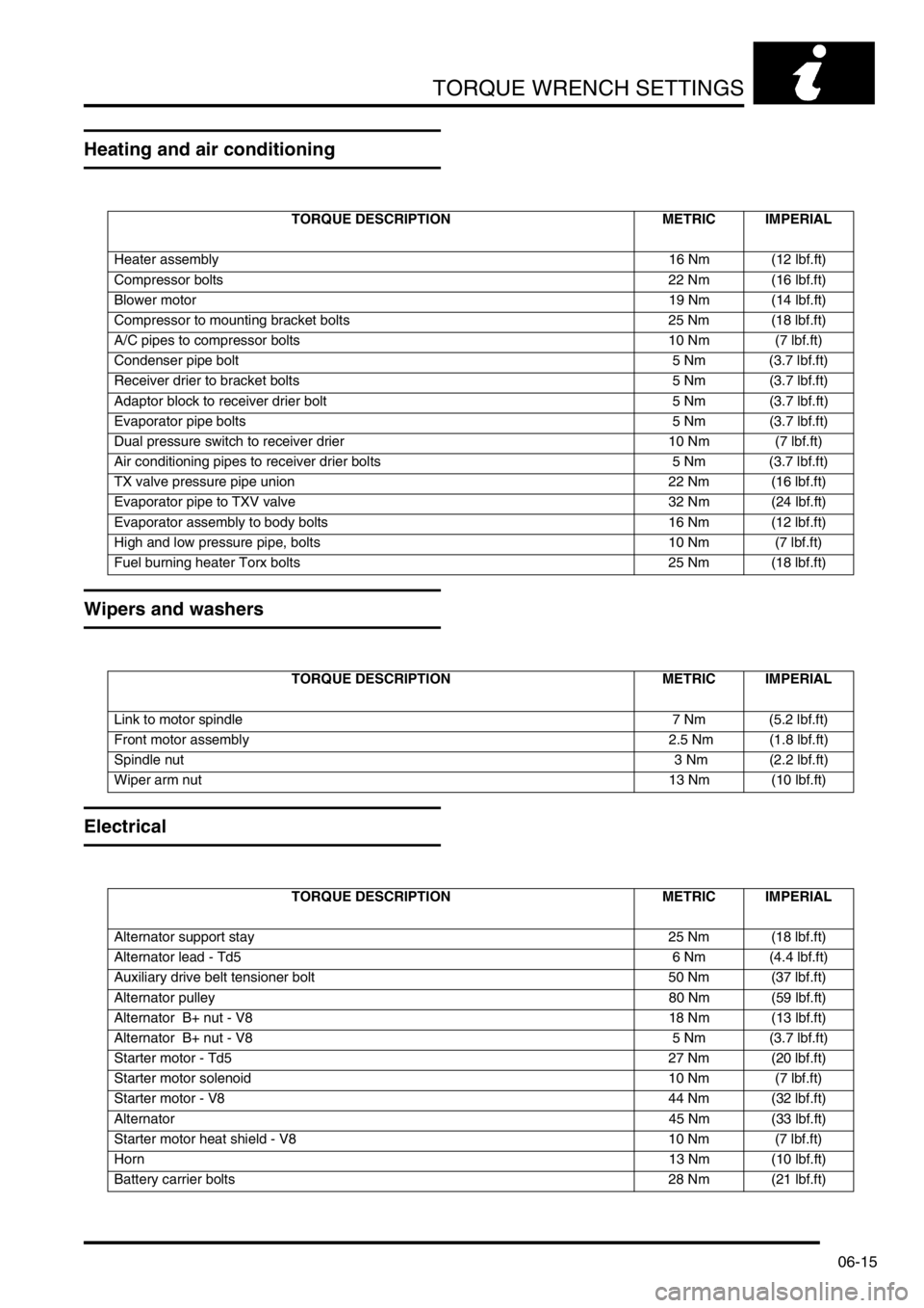
TORQUE WRENCH SETTINGS
06-15
Heating and air conditioning
Wipers and washers
Electrical
TORQUE DESCRIPTION METRIC IMPERIAL
Heater assembly16 Nm (12 lbf.ft)
Compressor bolts 22 Nm (16 lbf.ft)
Blower motor19 Nm (14 lbf.ft)
Compressor to mounting bracket bolts 25 Nm (18 lbf.ft)
A/C pipes to compressor bolts 10 Nm (7 lbf.ft)
Condenser pipe bolt 5 Nm (3.7 lbf.ft)
Receiver drier to bracket bolts 5 Nm (3.7 lbf.ft)
Adaptor block to receiver drier bolt 5 Nm (3.7 lbf.ft)
Evaporator pipe bolts 5 Nm (3.7 lbf.ft)
Dual pressure switch to receiver drier 10 Nm (7 lbf.ft)
Air conditioning pipes to receiver drier bolts 5 Nm (3.7 lbf.ft)
TX valve pressure pipe union 22 Nm (16 lbf.ft)
Evaporator pipe to TXV valve 32 Nm (24 lbf.ft)
Evaporator assembly to body bolts 16 Nm (12 lbf.ft)
High and low pressure pipe, bolts 10 Nm (7 lbf.ft)
Fuel burning heater Torx bolts 25 Nm (18 lbf.ft)
TORQUE DESCRIPTION METRIC IMPERIAL
Link to motor spindle 7 Nm (5.2 lbf.ft)
Front motor assembly 2.5 Nm (1.8 lbf.ft)
Spindle nut 3 Nm (2.2 lbf.ft)
Wiper arm nut13 Nm (10 lbf.ft)
TORQUE DESCRIPTION METRIC IMPERIAL
Alternator support stay 25 Nm (18 lbf.ft)
Alternator lead - Td5 6 Nm (4.4 lbf.ft)
Auxiliary drive belt tensioner bolt 50 Nm (37 lbf.ft)
Alternator pulley80 Nm (59 lbf.ft)
Alternator B+ nut - V8 18 Nm (13 lbf.ft)
Alternator B+ nut - V8 5 Nm (3.7 lbf.ft)
Starter motor - Td5 27 Nm (20 lbf.ft)
Starter motor solenoid 10 Nm (7 lbf.ft)
Starter motor - V8 44 Nm (32 lbf.ft)
Alternator45 Nm (33 lbf.ft)
Starter motor heat shield - V8 10 Nm (7 lbf.ft)
Horn13 Nm (10 lbf.ft)
Battery carrier bolts 28 Nm (21 lbf.ft)
Page 179 of 1672
ENGINE - TD5
12-1-40 REPAIRS
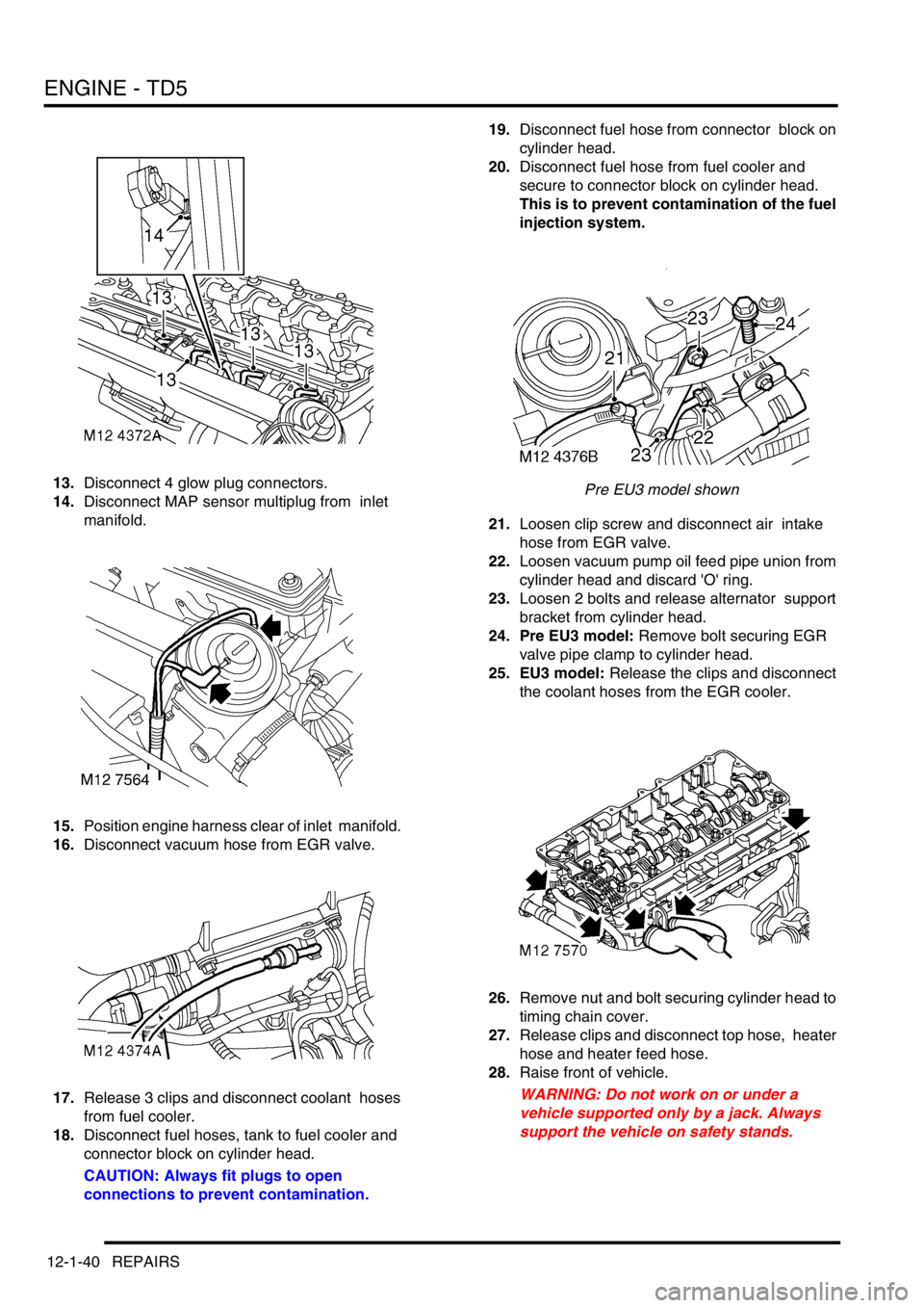
13.Disconnect 4 glow plug connectors.
14.Disconnect MAP sensor multiplug from inlet
manifold.
15.Position engine harness clear of inlet manifold.
16.Disconnect vacuum hose from EGR valve.
17.Release 3 clips and disconnect coolant hoses
from fuel cooler.
18.Disconnect fuel hoses, tank to fuel cooler and
connector block on cylinder head.
CAUTION: Always fit plugs to open
connections to prevent contamination.19.Disconnect fuel hose from connector block on
cylinder head.
20.Disconnect fuel hose from fuel cooler and
secure to connector block on cylinder head.
This is to prevent contamination of the fuel
injection system.
Pre EU3 model shown
21.Loosen clip screw and disconnect air intake
hose from EGR valve.
22.Loosen vacuum pump oil feed pipe union from
cylinder head and discard 'O' ring.
23.Loosen 2 bolts and release alternator support
bracket from cylinder head.
24. Pre EU3 model: Remove bolt securing EGR
valve pipe clamp to cylinder head.
25. EU3 model: Release the clips and disconnect
the coolant hoses from the EGR cooler.
26.Remove nut and bolt securing cylinder head to
timing chain cover.
27.Release clips and disconnect top hose, heater
hose and heater feed hose.
28.Raise front of vehicle.
WARNING: Do not work on or under a
vehicle supported only by a jack. Always
support the vehicle on safety stands.
Page 182 of 1672

ENGINE - TD5
REPAIRS 12-1-43
11.Clean camshaft sprocket and mating face on
camshaft.
12.Ensure engine is set to TDC No. 1 cylinder and
mark on camshaft sprocket is positioned
between the 2 coloured links.
13.Position camshaft sprocket to camshaft; fit and
lightly tighten new bolts, then loosen bolts half
a turn.
14.Clean timing chain fixed guide retaining pin and
apply Loctite 242 to threads.
15.Fit timing chain fixed guide retaining pin and
tighten to 25 Nm (18 lbf.ft) .
16.Clean timing chain tensioner and fit new
sealing washer.
17.Fit timing chain tensioner and tighten to 45 Nm
(22 lbf.ft).
18.Tighten bolts securing camshaft sprocket to
camshaft to 37 Nm (27 lbf.ft).
19.Remove tool LRT-12-058 from camshaft.
20.Remove tool LRT-12-158 from gearbox bell
housing.
21.Fit new camshaft bore blanking plug and 'O'-
ring seal in recess in cylinder head.
22.Clean vacuum pump union.
23.Tighten union securing vacuum pump oil feed
pipe to cylinder head to 10 Nm (7 lbf.ft) .
24.Fit bolts securing alternator support bracket to
cylinder head and tighten to 25 Nm (18 lbf.ft) .
25.Connect top hose and heater hoses and secure
with clips.
26. Pre EU3 model:Fit bolt securing EGR pipe
clamp to cylinder head bolt and tighten to 10
Nm (7 lbf.ft) .
27. EU3 model: Connect coolant hoses to EGR
cooler and secure with the clips.
28.Position air intake hose to EGR valve and
tighten clip screw.
29.Disconnect fuel hose from connector block and
connect to fuel cooler.
30.Connect fuel hoses to fuel cooler and
connector block on cylinder head.
31.Connect coolant hoses to fuel cooler and
secure clips.
32.Connect vacuum hose to EGR valve.
33.Position engine harness and connect multi
plugs and glow plug connectors.
34.Fit and tighten bolts, engine harness to
camshaft carrier.
35.Clean exhaust manifold and turbocharger
interface.
36.Fit new gasket to exhaust manifold, position
turbocharger and tighten – nuts securing
turbocharger to manifold to 30 Nm (22 lbf.ft).
37.Clean turbocharger oil feed hose bolt.
38.Position turbocharger oil feed hose using new
sealing washers. Fit banjo bolt securing
turbocharger oil feed hose and tighten to 25 Nm
(18 lbf.ft) . 39.Position exhaust manifold heatshield and
tighten M6 bolts to 9 Nm (7 lbf.ft) and M8 bolt to
25 Nm (18 lbf.ft).
40.Fit cooling fan coupling.
+ COOLING SYSTEM - Td5, REPAIRS,
Fan - viscous.
41.Fit camshaft cover with new seal.
+ ENGINE - Td5, REPAIRS, Gasket -
cover - camshaft.
42.Refill cooling system.
+ COOLING SYSTEM - Td5,
ADJUSTMENTS, Drain and refill.
43.Connect battery earth lead.
44.Fit battery cover and secure fixings.
45.Fit bonnet.
+ EXTERIOR FITTINGS, REPAIRS,
Bonnet.
Page 186 of 1672
ENGINE - TD5
REPAIRS 12-1-47
Engine and ancillaries
$% 12.41.01
Remove
1.Remove bonnet.
+ EXTERIOR FITTINGS, REPAIRS,
Bonnet.
2.Remove underbelly panel.
+ EXTERIOR FITTINGS, REPAIRS,
Panel - underbelly.
3.Drain engine oil.
+ MAINTENANCE, PROCEDURES,
Engine oil - diesel engine.
4.Remove radiator.
+ COOLING SYSTEM - Td5, REPAIRS,
Radiator.
5.Remove turbocharger.
+ ENGINE MANAGEMENT SYSTEM -
Td5, REPAIRS, Turbocharger.
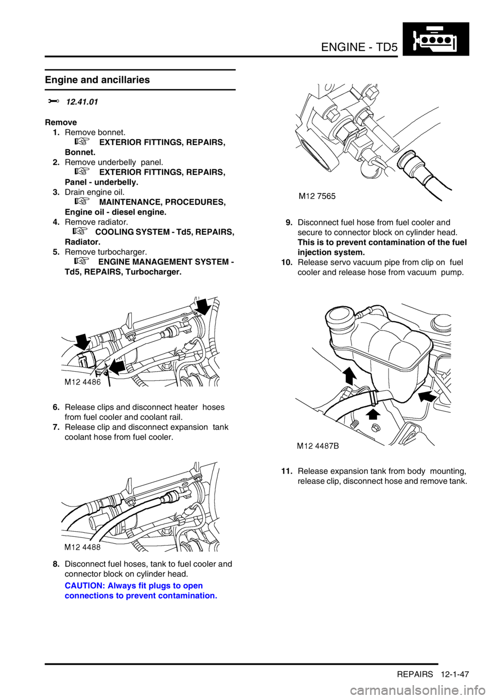
6.Release clips and disconnect heater hoses
from fuel cooler and coolant rail.
7.Release clip and disconnect expansion tank
coolant hose from fuel cooler.
8.Disconnect fuel hoses, tank to fuel cooler and
connector block on cylinder head.
CAUTION: Always fit plugs to open
connections to prevent contamination.9.Disconnect fuel hose from fuel cooler and
secure to connector block on cylinder head.
This is to prevent contamination of the fuel
injection system.
10.Release servo vacuum pipe from clip on fuel
cooler and release hose from vacuum pump.
11.Release expansion tank from body mounting,
release clip, disconnect hose and remove tank.
Page 189 of 1672
ENGINE - TD5
12-1-50 REPAIRS
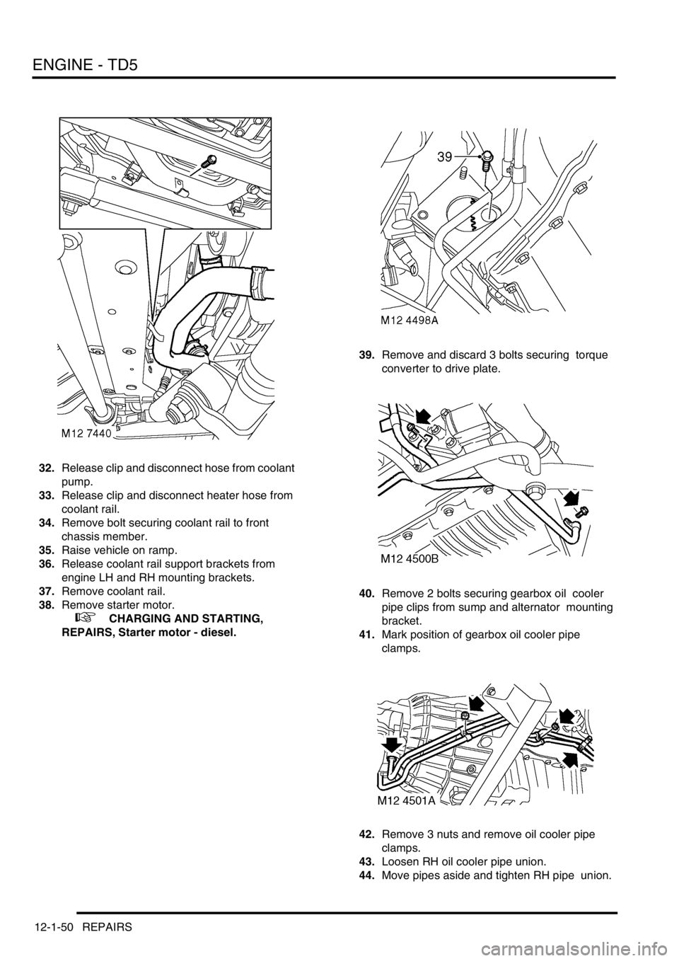
32.Release clip and disconnect hose from coolant
pump.
33.Release clip and disconnect heater hose from
coolant rail.
34.Remove bolt securing coolant rail to front
chassis member.
35.Raise vehicle on ramp.
36.Release coolant rail support brackets from
engine LH and RH mounting brackets.
37.Remove coolant rail.
38.Remove starter motor.
+ CHARGING AND STARTING,
REPAIRS, Starter motor - diesel.39.Remove and discard 3 bolts securing torque
converter to drive plate.
40.Remove 2 bolts securing gearbox oil cooler
pipe clips from sump and alternator mounting
bracket.
41.Mark position of gearbox oil cooler pipe
clamps.
42.Remove 3 nuts and remove oil cooler pipe
clamps.
43.Loosen RH oil cooler pipe union.
44.Move pipes aside and tighten RH pipe union.
Page 191 of 1672
ENGINE - TD5
12-1-52 REPAIRS
5.Fit 2 upper bolts securing engine oil cooler pipe
and gearbox housing to engine and tighten to
50 Nm (37 lbf.ft) .
6.Lower engine onto mountings, and tighten nuts
to 85 Nm (63 lbf.ft) .
7.Remove tool LRT-12-138 from engine.
8.Fit and tighten bolt securing engine closing
panel to gearbox.
9.Raise vehicle on ramp.
10.Fit nuts and bolts securing engine LH and RH
mountings to chassis and tighten to 85 Nm (63
lbf.ft).
11.Fit remaining bolts securing gearbox housing to
engine and tighten to 50 Nm (37 lbf.ft).
12.Rotate crankshaft and align drive plate to
torque converter.
13.Using a magnetic socket, fit and tighten new
torque converter drive plate bolts to 50 Nm (37
lbf.ft) .
14.Fit front cross member and tighten bolts to 26
Nm (19 lbf.ft).
15.Align gearbox oil cooler pipes.
16.Fit oil cooler pipe clip and tighten bolts to 9 Nm
(7 lbf.ft).
17.Position gearbox oil cooler pipe clamps and
tighten nuts.
18.Position coolant rail and secure support bracket
in engine LH and RH mounting brackets.
19.Fit starter motor.
+ CHARGING AND STARTING,
REPAIRS, Starter motor - diesel.
20.Lower ramp.
21.Position coolant rail to front chassis member, fit
and tighten bolt to 10 Nm (7 lbf.ft).
22.Connect heater hose to coolant rail and secure
with clip.
23.Connect hose to coolant pump and secure with
clip.
24.Position PAS pump and tighten bolts to 25 Nm
(18 lbf.ft).
25.Position PAS pump pulley and lightly tighten
bolts.
26.Position ACE pump, fit bolts and tighten to 25
Nm (18 lbf.ft).
27.Position A/C compressor, fit bolts and tighten
to 25 Nm (18 lbf.ft).
28.Position ancillary drive belt, rotate tensioner
anti-clockwise and locate belt to pulleys.
29.Tighten PAS pump pulley bolts to 10 Nm (7
lbf.ft).
30.Position air intake hose to air cleaner and
secure clips.
31.Position engine harness and connect
multiplugs to compressor, MAF sensor,
turbocharger boost solenoid, AAP & IAT
sensor.
32.Position air inlet hose to turbocharger and
tighten clip. 33.Connect hoses to turbocharger boost solenoid
and secure clips.
34.Clean CKP sensor and mating face.
CAUTION: If originally fitted: Fit spacer to
CKP sensor.
35.Using new 'O' ring, fit CKP sensor, tighten CKP
sensor bolt to 9 Nm (7 lbf.ft) and connect
multiplug.
36.Connect multiplug to EGR modulator.
37.Connect engine earth lead to battery earth lead
and tighten bolt.
38.Connect engine harness multiplug to ECM and
main harness.
39.Connect engine harness multiplugs to fuse
box.
40.Position glow plug lead to fusebox and secure
with bolt.
41.Position battery and alternator leads to fusebox
and secure with bolts.
42.Fit engine compartment fuse box cover.
43.Connect vacuum hose to EGR valve.
44.Connect hose to vacuum pump and secure
vacuum pipe to fuel cooler.
45.Disconnect fuel hose from connector block and
connect to fuel cooler.
46.Connect fuel hoses to fuel cooler and
connector block on cylinder head.
47.Position expansion tank, connect hose and
secure with clip. Secure tank to body mounting.
48.Connect coolant hoses to fuel cooler and
coolant rail and secure clips.
49.Fit turbocharger.
+ ENGINE MANAGEMENT SYSTEM -
Td5, REPAIRS, Turbocharger.
50. Fit radiator.
+ COOLING SYSTEM - Td5, REPAIRS,
Radiator.
51.Fill engine with oil.
+ MAINTENANCE, PROCEDURES,
Engine oil - diesel engine.
52.Fit underbelly panel.
+ EXTERIOR FITTINGS, REPAIRS,
Panel - underbelly.
53.Fit bonnet.
+ EXTERIOR FITTINGS, REPAIRS,
Bonnet.
Page 209 of 1672
ENGINE - TD5
12-1-70 OVERHAUL
Gasket - exhaust manifold
$% 30.15.12.01
Disassembly
Note: The following procedure covers engines
fitted with or without an EGR cooler. The EGR
cooler is bolted to the front of the cylinder head.
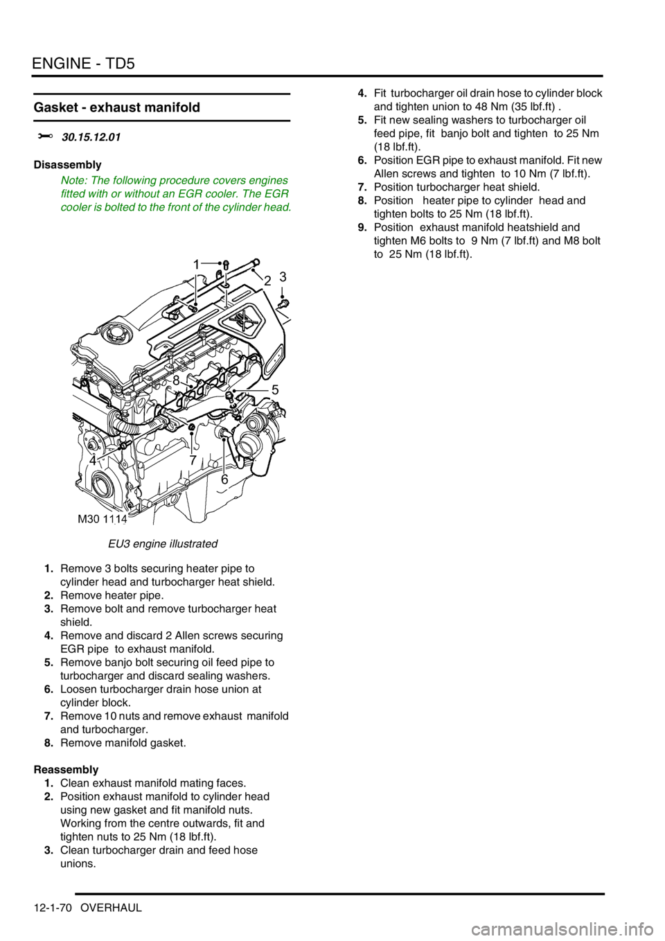
EU3 engine illustrated
1.Remove 3 bolts securing heater pipe to
cylinder head and turbocharger heat shield.
2.Remove heater pipe.
3.Remove bolt and remove turbocharger heat
shield.
4.Remove and discard 2 Allen screws securing
EGR pipe to exhaust manifold.
5.Remove banjo bolt securing oil feed pipe to
turbocharger and discard sealing washers.
6.Loosen turbocharger drain hose union at
cylinder block.
7.Remove 10 nuts and remove exhaust manifold
and turbocharger.
8.Remove manifold gasket.
Reassembly
1.Clean exhaust manifold mating faces.
2.Position exhaust manifold to cylinder head
using new gasket and fit manifold nuts.
Working from the centre outwards, fit and
tighten nuts to 25 Nm (18 lbf.ft).
3.Clean turbocharger drain and feed hose
unions. 4.Fit turbocharger oil drain hose to cylinder block
and tighten union to 48 Nm (35 lbf.ft) .
5.Fit new sealing washers to turbocharger oil
feed pipe, fit banjo bolt and tighten to 25 Nm
(18 lbf.ft).
6.Position EGR pipe to exhaust manifold. Fit new
Allen screws and tighten to 10 Nm (7 lbf.ft).
7.Position turbocharger heat shield.
8.Position heater pipe to cylinder head and
tighten bolts to 25 Nm (18 lbf.ft).
9.Position exhaust manifold heatshield and
tighten M6 bolts to 9 Nm (7 lbf.ft) and M8 bolt
to 25 Nm (18 lbf.ft).