engine overheat LAND ROVER DISCOVERY 2002 Workshop Manual
[x] Cancel search | Manufacturer: LAND ROVER, Model Year: 2002, Model line: DISCOVERY, Model: LAND ROVER DISCOVERY 2002Pages: 1672, PDF Size: 46.1 MB
Page 36 of 1672
GENERAL INFORMATION
03-1
GENERAL INFORMATION
General Precautions
Dangerous substances
Modern vehicles contain many materials and liquids
which if not handled with care can be hazardous to
both personal health and the environment.
WARNING: Many liquids and other substances
used in motor vehicles are poisonous and should
under no circumstances be consumed and
should, as far as possible, be kept from contact
with the skin. These liquids and substances
include acid, anti-freeze, asbestos, brake fluid,
fuel, windscreen washer additives, lubricants,
refrigerants and various adhesives.
Always read carefully the instructions printed on
labels or stamped on components and obey them
implicitly. Such instructions are included for
reasons of your health and personal safety.
Never disregard them.
Synthetic rubber
Many 'O' rings, seals, hoses, flexible pipes and other
similar items which appear to be natural rubber, are
in fact, made of synthetic materials called
Fluoroelastomers. Under normal operating
conditions this material is safe and does not present
a health hazard. However, if the material is damaged
by fire or excessive heating, it can break down and
produce highly corrosive Hydrofluoric acid.
Contact with Hydrofluoric acid can cause serious
burns on contact with skin. If skin contact does occur:
lRemove any contaminated clothing
immediately.
lIrrigate effected area of skin with a copious
amount of cold water or limewater for 15 to 60
minutes.
lObtain medical assistance immediately.
Should any material be in a burnt or overheated
condition, handle with extreme caution and wear
protective clothing (seamless industrial gloves,
protective apron etc.).
Decontaminate and dispose of gloves immediately
after use.Lubricating oils
Avoid excessive skin contact with used lubricating
oils and always adhere to the health protection
precautions.
WARNING: Avoid excessive skin contact with
used engine oil. Used engine oil contains
potentially harmful contaminants which may
cause skin cancer or other serious skin
disorders.
WARNING: Avoid excessive skin contact with
mineral oil. Mineral oils remove the natural fats
from the skin, leading to dryness, irritation and
dermatitis.
Health protection precautions
The following precautions should be observed at all
times.
lWear protective clothing, including impervious
gloves where practicable.
lAvoid prolonged and repeated contact with oils,
particularly used engine oils.
lDo not put oily rags in pockets.
lAvoid contaminating clothes (particularly those
next to the skin) with oil.
lOveralls must be cleaned regularly. Discard
heavily soiled clothing and oil impregnated
footwear.
lFirst aid treatment should be obtained
immediately for open cuts and wounds.
lApply barrier creams before each work period to
help prevent lubricating oil from contaminating
the skin.
lWash with soap and water to ensure all oil is
removed (proprietary skin cleansers and nail
brushes will help).
lUse moisturisers after cleaning; preparations
containing lanolin help replace the skin's natural
oils which have been removed.
lDo not use petrol/gasoline, kerosene, diesel
fuel, oil, thinners or solvents for cleaning skin.
lWhere practicable, degrease components prior
to handling.
lIf skin disorders develop, obtain medical advice
without delay.
lWear eye protection (e.g. goggles or face
shield) if there is a risk of eye contamination.
Eye wash facilities should be provided in close
vicinity of the work area.
Page 37 of 1672
GENERAL INFORMATION
03-2
Safety Instructions
Whenever possible, use a lift or pit when working
beneath vehicle, in preference to jacking. Chock
wheels as well as applying parking brake.
Jacking
Always use the recommended jacking points.
Always ensure that any lifting apparatus has
sufficient load capacity for the weight to be lifted.
Ensure the vehicle is standing on level ground prior
to lifting or jacking.
Apply the handbrake and chock the wheels.
WARNING: Do not work on or under a vehicle
supported only by a jack. Always support the
vehicle on safety stands.
Do not leave tools, lifting equipment, spilt oil, etc.
around or on the work bench area. Always keep a
clean and tidy work area.
Brake shoes and pads
Always fit the correct grade and specification of
brake linings. When renewing brake pads and brake
shoes, always replace as complete axle sets.Brake hydraulics
Observe the following recommendations when
working on the brake system:
lAlways use two spanners when loosening or
tightening brake pipe or hose connections.
lEnsure that hoses run in a natural curve and are
not kinked or twisted.
lFit brake pipes securely in their retaining clips
and ensure that the pipe cannot contact a
potential chafing point.
lContainers used for brake fluid must be kept
absolutely clean.
lDo not store brake fluid in an unsealed
container, it will absorb water and in this
condition would be dangerous to use due to a
lowering of its boiling point.
lDo not allow brake fluid to be contaminated with
mineral oil, or put new brake fluid in a container
which has previously contained mineral oil.
lDo not re-use brake fluid removed from the
system.
lAlways use clean brake fluid or a recommended
alternative to clean hydraulic components.
lAfter disconnection of brake pipes and hoses,
immediately fit suitable blanking caps or plugs to
prevent the ingress of dirt.
lOnly use the correct brake fittings with
compatible threads.
lObserve absolute cleanliness when working
with hydraulic components.
Cooling system caps and plugs
Extreme care is necessary when removing
expansion tank caps and coolant drain or bleed
screws when the engine is hot, especially if it is
overheated. To avoid the possibility of scalding,
allow the engine to cool before attempting removal.
Page 119 of 1672
MAINTENANCE
10-10 PROCEDURES
Spark plugs - V8 engine
Replace
Take great care when fitting spark plugs not
to cross-thread plug, otherwise costly
damage to cylinder head will result. It is
essential that correct grade of spark plugs
are fitted. Incorrect grade of spark plugs
may lead to piston overheating and engine
failure. Use only approved spark plugs, use
of unapproved spark plugs may cause the
misfire detection system to malfunction.
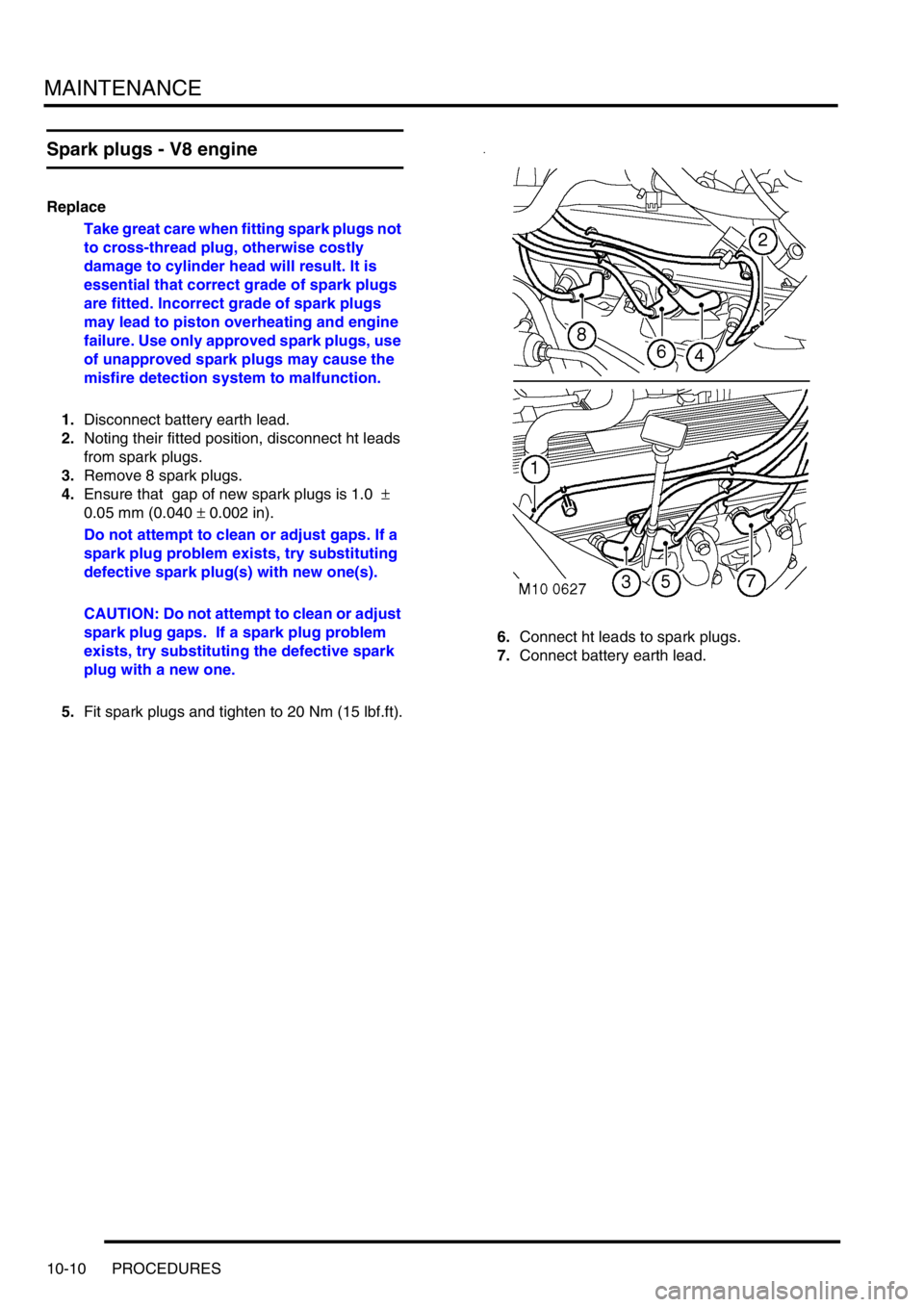
1.Disconnect battery earth lead.
2.Noting their fitted position, disconnect ht leads
from spark plugs.
3.Remove 8 spark plugs.
4.Ensure that gap of new spark plugs is 1.0
±
0.05 mm (0.040
± 0.002 in).
Do not attempt to clean or adjust gaps. If a
spark plug problem exists, try substituting
defective spark plug(s) with new one(s).
CAUTION: Do not attempt to clean or adjust
spark plug gaps. If a spark plug problem
exists, try substituting the defective spark
plug with a new one.
5.Fit spark plugs and tighten to 20 Nm (15 lbf.ft).6.Connect ht leads to spark plugs.
7.Connect battery earth lead.
Page 216 of 1672
ENGINE - TD5
OVERHAUL 12-1-77
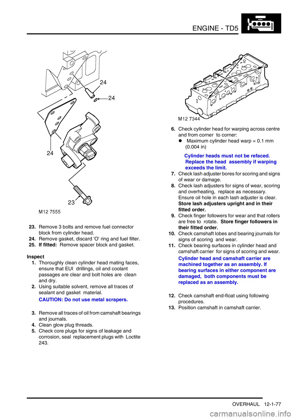
23.Remove 3 bolts and remove fuel connector
block from cylinder head.
24.Remove gasket, discard 'O' ring and fuel filter.
25. If fitted: Remove spacer block and gasket.
Inspect
1.Thoroughly clean cylinder head mating faces,
ensure that EUI drillings, oil and coolant
passages are clear and bolt holes are clean
and dry.
2.Using suitable solvent, remove all traces of
sealant and gasket material.
CAUTION: Do not use metal scrapers.
3.Remove all traces of oil from camshaft bearings
and journals.
4.Clean glow plug threads.
5.Check core plugs for signs of leakage and
corrosion, seal replacement plugs with Loctite
243.6.Check cylinder head for warping across centre
and from corner to corner:
l Maximum cylinder head warp = 0.1 mm
(0.004 in)
Cylinder heads must not be refaced.
Replace the head assembly if warping
exceeds the limit.
7.Check lash adjuster bores for scoring and signs
of wear or damage.
8.Check lash adjusters for signs of wear, scoring
and overheating, replace as necessary.
Ensure oil hole in each lash adjuster is clear.
Store lash adjusters upright and in their
fitted order.
9.Check finger followers for wear and that rollers
are free to rotate. Store finger followers in
their fitted order.
10.Check camshaft lobes and bearing journals for
signs of scoring and wear.
11.Check bearing surfaces in cylinder head and
camshaft carrier for signs of scoring and wear.
Cylinder head and camshaft carrier are
machined together as an assembly. If
bearing surfaces in either component are
damaged, both components must be
replaced as an assembly.
12.Check camshaft end-float using following
procedures.
13.Position camshaft in camshaft carrier.
Page 311 of 1672
ENGINE - V8
12-2-68 OVERHAUL
Inspect
1.Clean carbon from piston. Inspect piston for
distortion, cracks and burning.
2.Remove piston rings from piston.
3.Measure and record piston diameter at 90
° to
gudgeon pin axis and 10 mm (0.4 in) from
bottom of the skirt. The piston must be 0.02 to
0.045 mm (0.001 to 0.002 in) smaller than the
cylinder bore.
4.Check gudgeon pin bore in piston for signs of
wear and overheating.
5.Pistons fitted on production are graded 'A' or
'B', the grade letter is stamped on the piston
crown.
lPiston diameter: Grade 'A' = 93.970 to
93.985 mm (3.6996 to 3.7002 in).
lPiston diameter: Grade 'B' = 93.986 to 94.00
mm (3.7002 to 3.7007 in).
6.Worn cylinders fitted with grade 'A' pistons may
be honed to accept the grade 'B' piston
provided that specified cylinder bore and
ovality limits are maintained. Grade 'B'
pistons are supplied as service
replacements. Do not attempt to de-glaze
cylinder bores.
7.Check gudgeon pins for signs of wear and
overheating.
8.Check clearance of gudgeon pin in piston.
l Gudgeon pin to piston clearance = 0.006 to
0.015 mm (0.0002 to 0.0006 in).
9.Check overall dimensions of gudgeon pin.
Gudgeon pins are only supplied as an
assembly with replacement pistons.
lGudgeon pin length = 60.00 to 60.50 mm
(2.362 to 2.382 in).
lGudgeon pin diameter = 23.995 to 24.00
mm (0.9446 to 0.9448 in)10.Measure cylinder bore wear and ovality in two
axis 40 to 50 mm (1.6 to 2 in) from top of bore.
The temperature of piston and cylinder
block must be the same to ensure accurate
measurement. Do not attempt to de-glaze
cylinder bores.
lGrade 'A' pistons: Cylinder bore = 94.00 to
94.015 mm (3.7007 to 3.7013 in).
lGrade 'B' pistons: Cylinder bore = 94.016 to
94.030 mm (3.7014 to 3.7019 in).
lMaximum ovality = 0.013 mm (0.0005 in).
11.Check alignment of connecting rods.
Reassembly
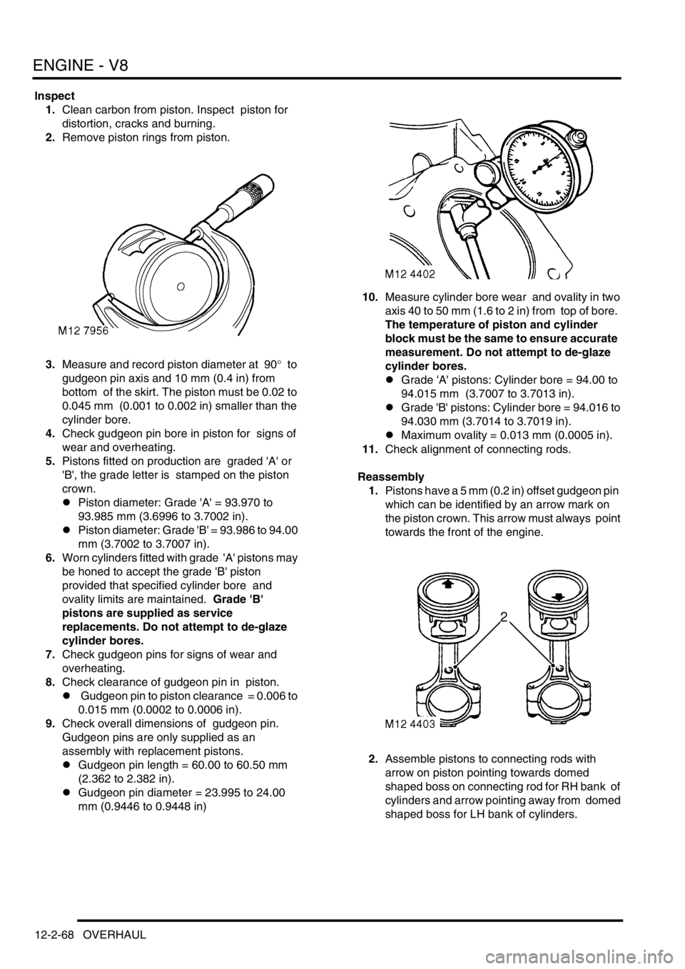
1.Pistons have a 5 mm (0.2 in) offset gudgeon pin
which can be identified by an arrow mark on
the piston crown. This arrow must always point
towards the front of the engine.
2.Assemble pistons to connecting rods with
arrow on piston pointing towards domed
shaped boss on connecting rod for RH bank of
cylinders and arrow pointing away from domed
shaped boss for LH bank of cylinders.
Page 347 of 1672
EMISSION CONTROL - V8
17-2-10 DESCRIPTION AND OPERATION
A spiral oil separator is located in the stub pipe to the ventilation hose on the right hand cylinder head rocker cover,
where oil is separated and returned to the cylinder head. The rubber ventilation hose from the right hand rocker cover
is routed to a port on the right hand side of the inlet manifold plenum chamber where the returned gases mix with the
fresh inlet air passing through the throttle butterfly valve. The stub pipe on the left hand rocker cover does not contain
an oil separator, and the ventilation hose is routed to the throttle body housing at the air inlet side of the butterfly valve.
The ventilation hoses are attached to the stub pipe by metal band clamps.
Exhaust emission control system
The fuel injection system provides accurately metered quantities of fuel to the combustion chambers to ensure the
most efficient air to fuel ratio under all operating conditions. A further improvement to combustion is made by
measuring the oxygen content of the exhaust gases to enable the quantity of fuel injected to be varied in accordance
with the prevailing engine operation and ambient conditions; any unsatisfactory composition of the exhaust gas is
then corrected by adjustments made to the fuelling by the ECM.
The main components of the exhaust emission system are two catalytic converters which are an integral part of the
front exhaust pipe assembly. The catalytic converters are included in the system to reduce the emission to
atmosphere of carbon monoxide (CO), oxides of nitrogen (NO
x) and hydrocarbons (HC). The active constituents of
the catalytic converters are platinum (Pt), palladium (PD) and rhodium (Rh). Catalytic converters for NAS low
emission vehicles (LEVs) from 2000MY have active constituents of palladium and rhodium only. The correct
functioning of the converters is dependent upon close control of the oxygen concentration in the exhaust gas entering
the catalyst.
The two catalytic converters are shaped differently to allow sufficient clearance between the body and transmission,
but they remain functionally identical since they have the same volume and use the same active constituents.
The basic control loop comprises the engine (controlled system), the heated oxygen sensors (measuring elements),
the engine management ECM (control) and the injectors and ignition (actuators). Other factors also influence the
calculations of the ECM, such as air flow, air intake temperature and throttle position. Additionally, special driving
conditions are compensated for, such as starting, acceleration, deceleration, overrun and full load.
The reliability of the ignition system is critical for efficient catalytic converter operation, since misfiring will lead to
irreparable damage of the catalytic converter due to the overheating that occurs when unburned combustion gases
are burnt inside it.
CAUTION: If the engine is misfiring, it should be shut down immediately and the cause rectified. Failure to do
so will result in irreparable damage to the catalytic converter.
CAUTION: Ensure the exhaust system is free from leaks. Exhaust gas leaks upstream of the catalytic
converter could cause internal damage to the catalytic converter.
CAUTION: Serious damage to the engine may occur if a lower octane number fuel than recommended is used.
Serious damage to the catalytic converter and oxygen sensors will occur if leaded fuel is used.
Air : fuel ratio
The theoretical ideal air:fuel ratio to ensure complete combustion and minimise emissions in a spark-ignition engine
is 14.7:1 and is referred to as the stoichiometric ratio.
The excess air factor is denoted by the Lambda symbol
λ, and is used to indicate how far the air:fuel mixture ratio
deviates from the theoretical optimum during any particular operating condition.
lWhen
λ = 1, the air to fuel ratio corresponds to the theoretical optimum of 14.7:1 and is the desired condition for
minimising emissions.
lWhen
λ > 1, (i.e. λ = 1.05 to λ = 1.3) there is excess air available (lean mixture) and lower fuel consumption can
be attained at the cost of reduced performance. For mixtures above
λ = 1.3, the mixture ceases to be ignitable.
lWhen
λ < 1, (i.e. λ = 0.85 to λ = 0.95) there is an air deficiency (rich mixture) and maximum output is available,
but fuel economy is impaired.
The engine management system used with V8 engines operates in a narrower control range about the stoichiometric
ideal between
λ = 0.97 to 1.03 using closed-loop control techniques. When the engine is warmed up and operating
under normal conditions, it is essential to maintain
λ close to the ideal (λ = 1) to ensure the effective treatment of
exhaust gases by the three-way catalytic converters installed in the downpipes from each exhaust manifold.
Page 379 of 1672

EMISSION CONTROL - V8
17-2-42 DESCRIPTION AND OPERATION
Secondary air injection system
When the engine is started, the engine control module checks the engine coolant temperature and if it is below 55°
C, the ECM grounds the electrical connection to the coil of the secondary air injection (SAI) pump relay.
A 12V battery supply is fed to the inertia switch via fuse 13 in the engine compartment fusebox. When the inertia
switch contacts are closed, the feed passes through the switch and is connected to the coil of the Main relay. An earth
connection from the Main relay coil is connected to the ECM. When the ECM completes the earth path, the coil
energises and closes the contacts of the Main relay.
The Main and Secondary Air Injection (SAI) pump relays are located in the engine compartment fusebox. When the
contacts of the Main relay are closed, a 12V battery supply is fed to the coil of the SAI pump relay. An earth connection
from the coil of the SAI pump relay is connected to the ECM. When the ECM completes the earth path, the coil
energises and closes the contacts of the SAI pump relay to supply 12V to the SAI pump via fusible link 2 in the engine
compartment fusebox. The SAI pump starts to operate, and will continue to do so until the ECM switches off the earth
connection to the coil of the SAI pump relay.
The SAI pump remains operational for a period determined by the ECM and depends on the starting temperature of
the engine, or for a maximum operation period determined by the ECM if the target engine coolant temperature has
not been reached in the usual time.
When the contacts of the main relay are closed, a 12V battery supply is fed to the SAI solenoid valve via Fuse 2 in
the engine compartment fusebox.
The ECM grounds the electrical connection to the SAI vacuum solenoid valve at the same time as it switches on the
SAI pump motor. When the SAI vacuum solenoid valve is energised, a vacuum is provided to the operation control
ports on both of the vacuum operated SAI control valves at the exhaust manifolds. The control vacuum is sourced
from the intake manifold depression and routed to the SAI control valves via a vacuum reservoir and the SAI vacuum
solenoid valve.
The vacuum reservoir is included in the vacuum supply circuit to prevent vacuum fluctuations caused by changes in
the intake manifold depression affecting the operation of the SAI control valves.
When a vacuum is applied to the control ports of the SAI control valves, the valves open to allow pressurised air from
the SAI pump to pass through to the exhaust ports in the cylinder heads for combustion.
When the ECM has determined that the SAI pump has operated for the desired duration, it switches off the earth paths
to the SAI pump relay and the SAI vacuum solenoid valve. With the SAI vacuum solenoid valve de-energised, the
valve closes, cutting off the vacuum supply to the SAI control valves. The SAI control valves close immediately and
completely to prevent any further pressurised air from the SAI pump entering the exhaust manifolds.
The engine coolant temperature sensor incurs a time lag in respect of detecting a change in temperature and the SAI
pump automatically enters a 'soak period' between operations to prevent the SAI pump overheating. The ECM also
compares the switch off and start up temperatures, to determine whether it is necessary to operate the SAI pump.
This prevents the pump running repeatedly and overheating on repeat starts.
Other factors which may prevent or stop SAI pump operation include the prevailing engine speed / load conditions.
Page 424 of 1672

ENGINE MANAGEMENT SYSTEM - TD5
DESCRIPTION AND OPERATION 18-1-31
The purpose of the glow plugs is:
lAssist cold engine start.
lReduce exhaust emissions at low engine load/speed.
The main part of the glow plug is a tubular heating element that protrudes into the combustion chamber of the engine.
The heating element contains a spiral filament that is encased in magnesium oxide powder. At the tip of the tubular
heating element is the heater coil. Behind the heater coil and connected in series is a control coil. The control coil
regulates the heater coil to ensure that it does not overheat and cause a possible failure. The glow plug circuit has its
own control relay located in the engine compartment fuse box.
Pre-heat is the length of time the glow plugs operate prior to engine cranking. The ECM controls the pre-heat time of
the glow plugs based on battery voltage and coolant temperature information via the glow plug relay.
Post-heat is the length of time the glow plugs operate after the engine starts. The ECM controls the post-heat time
based on ECT information. If the ECT fails the ECM will operate pre/post-heat time strategies with default values from
its memory. The engine will be difficult to start.
Input/Output
The glow plugs receive voltage from the glow plug relay that is controlled by the ECM. The ECM provides the earth
path for the relay coil closing the relay contacts and supplying the glow plugs with battery voltage. The supply voltage
heats the coils to approximately 1000
°C (1832 °F). The glow plug circuit is wired in parallel, the body of each glow
plug is screwed directly into the engine block which provides each glow plug with an earth path.
The glow plugs can fail in the following ways:
lHeater coil open circuit.
lControl coil open circuit.
lPoor earth quality.
lShort circuit to vehicle supply.
lShort circuit to vehicle earth.
lWiring loom fault.
lRelay windings open circuit.
lIncorrect relay fitted.
In the event of a glow plug failure any of the following symptoms may be observed:
lDifficult starting.
lExcessive smoke emissions after engine start.
Page 492 of 1672
ENGINE MANAGEMENT SYSTEM - V8
DESCRIPTION AND OPERATION 18-2-35
Ignition coils
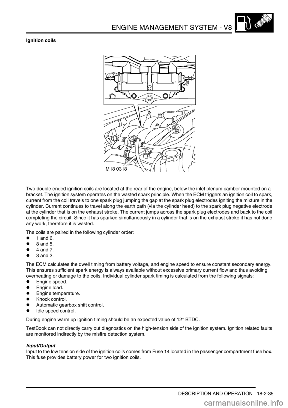
Two double ended ignition coils are located at the rear of the engine, below the inlet plenum camber mounted on a
bracket. The ignition system operates on the wasted spark principle. When the ECM triggers an ignition coil to spark,
current from the coil travels to one spark plug jumping the gap at the spark plug electrodes igniting the mixture in the
cylinder. Current continues to travel along the earth path (via the cylinder head) to the spark plug negative electrode
at the cylinder that is on the exhaust stroke. The current jumps across the spark plug electrodes and back to the coil
completing the circuit. Since it has sparked simultaneously in a cylinder that is on the exhaust stroke it has not done
any work, therefore it is wasted.
The coils are paired in the following cylinder order:
l1 and 6.
l8 and 5.
l4 and 7.
l3 and 2.
The ECM calculates the dwell timing from battery voltage, and engine speed to ensure constant secondary energy.
This ensures sufficient spark energy is always available without excessive primary current flow and thus avoiding
overheating or damage to the coils. Individual cylinder spark timing is calculated from the following signals:
lEngine speed.
lEngine load.
lEngine temperature.
lKnock control.
lAutomatic gearbox shift control.
lIdle speed control.
During engine warm up ignition timing should be an expected value of 12
° BTDC.
TestBook can not directly carry out diagnostics on the high-tension side of the ignition system. Ignition related faults
are monitored indirectly by the misfire detection system.
Input/Output
Input to the low tension side of the ignition coils comes from Fuse 14 located in the passenger compartment fuse box.
This fuse provides battery power for two ignition coils.
Page 589 of 1672

COOLING SYSTEM - TD5
26-1-6 DESCRIPTION AND OPERATION
Outlet housing
A cast aluminium outlet housing is attached to the cylinder head with three bolts and sealed with a gasket. Coolant
leaves the engine through the outlet housing and is directed through a hose to the heater matrix, the radiator or the
by-pass circuit.
An Engine Coolant Temperature (ECT) sensor is installed in a threaded port on the side of the outlet housing. The
sensor monitors coolant temperature emerging from the engine and sends signals to the Engine Control Module
(ECM) for engine management and temperature gauge operation.
+ ENGINE MANAGEMENT SYSTEM - Td5, DESCRIPTION AND OPERATION, Description.
Expansion tank
The expansion tank is located in the engine compartment. The tank is made from moulded plastic and attached to
brackets on the right hand inner wing. A maximum coolant when cold level is moulded onto the tank.
Excess coolant created by heat expansion is returned to the expansion tank from the radiator bleed pipe at the top of
the radiator. An outlet pipe is connected into the coolant pump feed hose and replaces the coolant displaced by heat
expansion into the system when the engine is cool.
The expansion tank is fitted with a sealed pressure cap. The cap contains a pressure relief valve which opens to allow
excessive pressure and coolant to vent through the overflow pipe. The relief valve is open at a pressure of 1.4 bar (20
lbf.in
2) and above.
Heater matrix
The heater matrix is fitted in the heater assembly inside the passenger compartment. Two pipes pass through the
bulkhead into the engine compartment and provide coolant flow to and from the matrix. The pipes from the bulkhead
are connected to the matrix, sealed with 'O' rings and clamped with circular rings.
The matrix is constructed from aluminium with two end tanks interconnected with tubes. Aluminium fins are located
between the tubes and conduct heat from the hot coolant flowing through the tubes. Air from the heater assembly is
warmed as it passes through the matrix fins. The warm air is then distributed in to the passenger compartment as
required.
+ HEATING AND VENTILATION, DESCRIPTION AND OPERATION, Description.
When the engine is running, coolant from the engine is constantly circulated through the heater matrix.
Radiator
The 44 row radiator is located at the front of the vehicle in the engine compartment. The cross flow type radiator is
manufactured from aluminium with moulded plastic end tanks interconnected with tubes. The bottom four rows are
separate from the upper radiator and form the lower radiator for the fuel cooler. Aluminium fins are located between
the tubes and conduct heat from the hot coolant flowing through the tubes, reducing the coolant temperature as it
flows through the radiator. Air intake from the front of the vehicle when moving carries the heat away from the fins.
When the vehicle is stationary, the viscous fan draws air through the radiator fins to prevent the engine from
overheating.
Two connections at the top of the radiator provide for the attachment of the top hose from the outlet housing and bleed
pipe to the expansion tank. Three connections at the bottom of the radiator allow for the attachment of the bottom
hose to the thermostat housing and the return hose from the oil cooler and the feed hose to the fuel cooler.
The bottom four rows of the lower radiator are dedicated to the fuel cooler. The upper of the two connections at the
bottom of the radiator receives coolant from the oil cooler. This is fed through the four rows of the lower radiator in a
dual pass and emerges at the lower connection. The dual pass lowers the coolant temperature by up to 24
°C before
being passed to the fuel cooler.
Two smaller radiators are located in front of the cooling radiator. The upper radiator is the intercooler for the air intake
system and the lower radiator provides cooling of the gearbox oil.
+ EMISSION CONTROL - Td5, DESCRIPTION AND OPERATION, Emission Control Systems.
+ MANUAL GEARBOX - R380, DESCRIPTION AND OPERATION, Description.
+ AUTOMATIC GEARBOX - ZF4HP22 - 24, DESCRIPTION AND OPERATION, Description.