fuses LAND ROVER DISCOVERY 2002 Workshop Manual
[x] Cancel search | Manufacturer: LAND ROVER, Model Year: 2002, Model line: DISCOVERY, Model: LAND ROVER DISCOVERY 2002Pages: 1672, PDF Size: 46.1 MB
Page 1189 of 1672

SEATS
76-5-4 DESCRIPTION AND OPERATION
Description - electric seats
General
All markets use the same electric seat system. Electically operated lumbar support is optional. The system consists
of an electrical sub-system and a mechanical sub-system.
The electrical sub-system consists of the following components:
lBCU.
lSeat power relays.
lSeat switch packs.
lSeat fore/ aft motors.
lSeat cushion front up/ down motors.
lSeat cushion rear up/ down motors.
lSeat squab motor.
lLumbar pump.
lLumbar deflate solenoid.
The mechanical sub-system consist of the following components:
lGear wheels.
lRack and pinion assemblies.
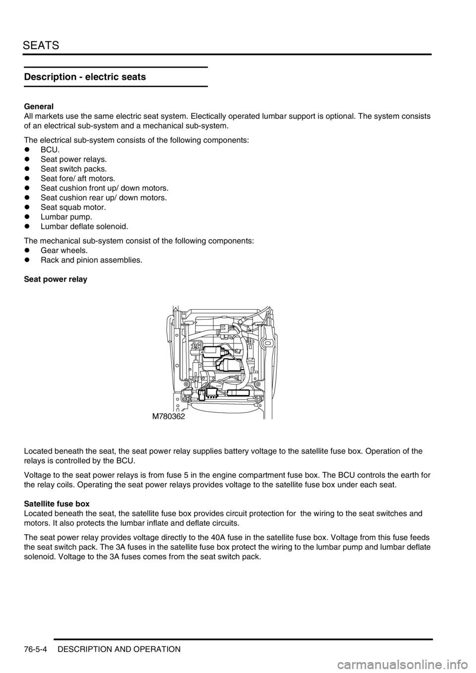
Seat power relay
Located beneath the seat, the seat power relay supplies battery voltage to the satellite fuse box. Operation of the
relays is controlled by the BCU.
Voltage to the seat power relays is from fuse 5 in the engine compartment fuse box. The BCU controls the earth for
the relay coils. Operating the seat power relays provides voltage to the satellite fuse box under each seat.
Satellite fuse box
Located beneath the seat, the satellite fuse box provides circuit protection for the wiring to the seat switches and
motors. It also protects the lumbar inflate and deflate circuits.
The seat power relay provides voltage directly to the 40A fuse in the satellite fuse box. Voltage from this fuse feeds
the seat switch pack. The 3A fuses in the satellite fuse box protect the wiring to the lumbar pump and lumbar deflate
solenoid. Voltage to the 3A fuses comes from the seat switch pack.
Page 1496 of 1672

BODY CONTROL UNIT
DESCRIPTION AND OPERATION 86-3-27
The electrically controlled seats are operated when the ignition switch is in position I or II or for a predetermined period
when the driver's door is open. If the ignition state is in crank, the seat enable relay is off. If the ignition state is off and
the driver's door open input is off, the seat enable relay is off. If the ignition state is off and the driver's door open input
is on and transit mode is on, the seat enable relay output is off.
The power supply to each seat switch pack is powered from a power seat relay located on the underside of each seat
frame. The feed from the relay is protected by a fuse located in a satellite fuse block located adjacent to the power
seat relay. The fuse block also contains two additional fuses which are used to protect the feeds to the lumbar pump
and solenoid.
With the ignition switch in position I or II or the driver's door open, the BCU provides an earth path for the coils of the
LH and RH power seat relays, energising the relays and closing the contacts. If the driver's door input signal is on for
longer than 45 seconds with the ignition switched off, the seat enable relay is switched off.
Direction indicators and hazard warning lamps
The BCU supplies reference voltages for the LH and RH indicators. When the direction indicator switch is used to
select the LH or RH indicator position, an earth path is completed which signals the BCU that a request for direction
indicator operation has been made. The BCU then communicates this request to the IDM which supplies an earth
path for the coil of the relevant relay (LH or RH indicator relay). When the relay coil is energised, the relay contacts
close and a voltage supply is provided via a resistor to the relevant direction indicators. The IDM controls the timing
of the flash operations by continually removing and restoring the earth path to the direction indicator relay coil.
The BCU checks for the following inputs for performing the logic operations associated with the direction indicator
lamps:
lIgnition state.
lRH indicators selected.
lLH indicators selected.
lHazards selected.
lInertia switch hazard request.
lOne short indicator flash request (anti-theft system arming).
lTwo short indicator flash request (superlocking).
lOne long indicator flash request (anti-theft system disarming).
lAlarm flashing indicators (anti-theft alarm triggered).
The following outputs are provided by the BCU as a result of the inputs received and the logical operations performed:
lRH indicators enable.
lLH indicators enable.
lDirection indicator left message (link to IDM).
lDirection indicator right message (link to IDM).
Direction indicator lamp failure detection
The BCU uses the following logic inputs to determine if there is a direction indicator bulb failure or if the presence of
a trailer is detected. The BCU uses the information to decide which output to enable at any particular instance:
lRight direction indicators requested.
lLeft direction indicators requested.
lRH indicators current sense.
lLH indicators current sense.
If a direction indicator bulb failure or a trailer presence is detected, the following outputs can be generated depending
on the BCU logic states:
lTrailer detected.
lBulb failure detected.
lDirection indicator short circuit.
lDirection indicator relay stuck.