jack points LAND ROVER DISCOVERY 2002 Workshop Manual
[x] Cancel search | Manufacturer: LAND ROVER, Model Year: 2002, Model line: DISCOVERY, Model: LAND ROVER DISCOVERY 2002Pages: 1672, PDF Size: 46.1 MB
Page 37 of 1672

GENERAL INFORMATION
03-2
Safety Instructions
Whenever possible, use a lift or pit when working
beneath vehicle, in preference to jacking. Chock
wheels as well as applying parking brake.
Jacking
Always use the recommended jacking points.
Always ensure that any lifting apparatus has
sufficient load capacity for the weight to be lifted.
Ensure the vehicle is standing on level ground prior
to lifting or jacking.
Apply the handbrake and chock the wheels.
WARNING: Do not work on or under a vehicle
supported only by a jack. Always support the
vehicle on safety stands.
Do not leave tools, lifting equipment, spilt oil, etc.
around or on the work bench area. Always keep a
clean and tidy work area.
Brake shoes and pads
Always fit the correct grade and specification of
brake linings. When renewing brake pads and brake
shoes, always replace as complete axle sets.Brake hydraulics
Observe the following recommendations when
working on the brake system:
lAlways use two spanners when loosening or
tightening brake pipe or hose connections.
lEnsure that hoses run in a natural curve and are
not kinked or twisted.
lFit brake pipes securely in their retaining clips
and ensure that the pipe cannot contact a
potential chafing point.
lContainers used for brake fluid must be kept
absolutely clean.
lDo not store brake fluid in an unsealed
container, it will absorb water and in this
condition would be dangerous to use due to a
lowering of its boiling point.
lDo not allow brake fluid to be contaminated with
mineral oil, or put new brake fluid in a container
which has previously contained mineral oil.
lDo not re-use brake fluid removed from the
system.
lAlways use clean brake fluid or a recommended
alternative to clean hydraulic components.
lAfter disconnection of brake pipes and hoses,
immediately fit suitable blanking caps or plugs to
prevent the ingress of dirt.
lOnly use the correct brake fittings with
compatible threads.
lObserve absolute cleanliness when working
with hydraulic components.
Cooling system caps and plugs
Extreme care is necessary when removing
expansion tank caps and coolant drain or bleed
screws when the engine is hot, especially if it is
overheated. To avoid the possibility of scalding,
allow the engine to cool before attempting removal.
Page 102 of 1672

LIFTING AND TOWING
08-1
LIFTING AND TOWING
LIFTING
The following instructions must be carried out before
raising the vehicle off the ground.
lUse a solid level ground surface.
lApply hand brake.
lSelect 'P' (Automatic gearbox) or 1st gear
(Manual gearbox) in main gearbox.
lSelect Low range in transfer gearbox.
To avoid damage occurring to the under body
components of the vehicle the following jacking
procedures must be adhered to.
DO NOT POSITION JACKS OR AXLE STANDS
UNDER THE FOLLOWING COMPONENTS:
lBody structure
lBumpers
lFuel lines
lBrake lines
lFront radius arms
lPanhard rod
lSteering linkage
lRear trailing arms
lFuel tank
lEngine sump
lGearbox bell housing
Vehicle jack
The jack provided with the vehicle is only intended for
use in an emergency, for changing a tyre. DO NOT
use the jack for any other purpose. Refer to Owner's
Handbook for vehicle jack location points and
procedure. Never work under a vehicle supported
solely by the vehicle jack.
Hydraulic jack
A hydraulic jack with a minimum 1500 kg, 3,300 lbs
load capacity must be used. Do not commence
work on the underside of the vehicle until
suitable axle stands have been positioned under
the axle.
WARNING: Always chock the wheels when
jacking. The hand brake acts on the
transmission, not the rear wheels, and may be
ineffective when the wheels are off the ground.Raising and supporting the vehicle
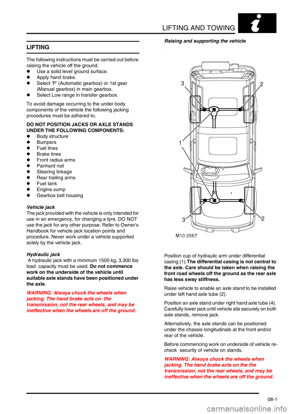
Position cup of hydraulic arm under differential
casing (1).The differential casing is not central to
the axle. Care should be taken when raising the
front road wheels off the ground as the rear axle
has less sway stiffness.
Raise vehicle to enable an axle stand to be installed
under left hand axle tube (2).
Position an axle stand under right hand axle tube (4).
Carefully lower jack until vehicle sits securely on both
axle stands, remove jack.
Alternatively, the axle stands can be positioned
under the chassis longitudinals at the front and/or
rear of the vehicle.
Before commencing work on underside of vehicle re-
check security of vehicle on stands.
WARNING: Always chock the wheels when
jacking. The hand brake acts on the the
transmission, not the rear wheels, and may be
ineffective when the wheels are off the ground.
Page 666 of 1672

CLUTCH - TD5
REPAIRS 33-1-15
Bearing and lever - clutch release
$% 33.25.12
Remove
1.Remove gearbox assembly.
+ MANUAL GEARBOX - R380,
REPAIRS, Gearbox - Diesel.
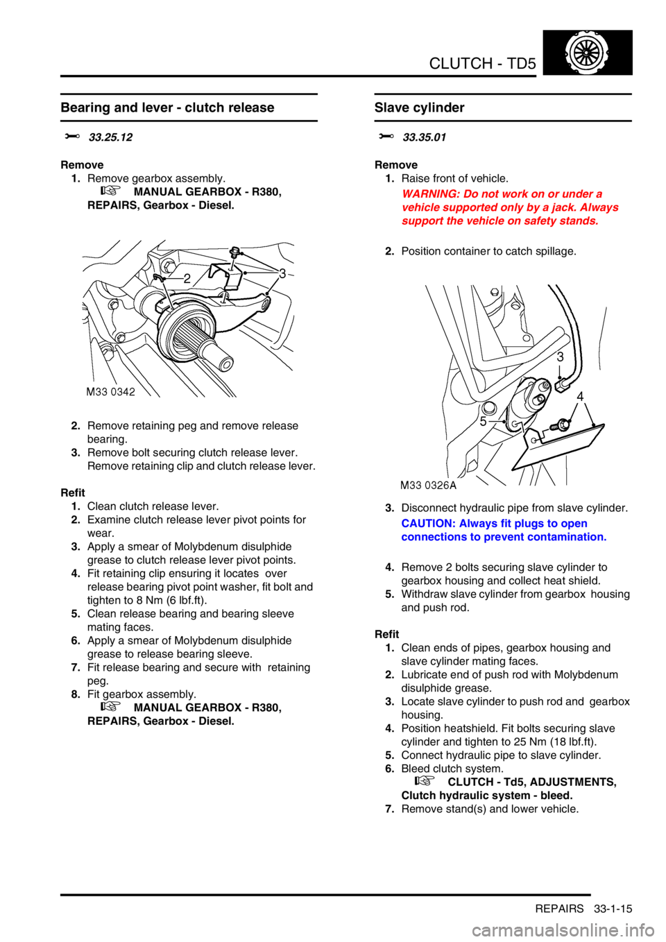
2.Remove retaining peg and remove release
bearing.
3.Remove bolt securing clutch release lever.
Remove retaining clip and clutch release lever.
Refit
1.Clean clutch release lever.
2.Examine clutch release lever pivot points for
wear.
3.Apply a smear of Molybdenum disulphide
grease to clutch release lever pivot points.
4.Fit retaining clip ensuring it locates over
release bearing pivot point washer, fit bolt and
tighten to 8 Nm (6 lbf.ft).
5.Clean release bearing and bearing sleeve
mating faces.
6.Apply a smear of Molybdenum disulphide
grease to release bearing sleeve.
7.Fit release bearing and secure with retaining
peg.
8.Fit gearbox assembly.
+ MANUAL GEARBOX - R380,
REPAIRS, Gearbox - Diesel.
Slave cylinder
$% 33.35.01
Remove
1.Raise front of vehicle.
WARNING: Do not work on or under a
vehicle supported only by a jack. Always
support the vehicle on safety stands.
2.Position container to catch spillage.
3.Disconnect hydraulic pipe from slave cylinder.
CAUTION: Always fit plugs to open
connections to prevent contamination.
4.Remove 2 bolts securing slave cylinder to
gearbox housing and collect heat shield.
5.Withdraw slave cylinder from gearbox housing
and push rod.
Refit
1.Clean ends of pipes, gearbox housing and
slave cylinder mating faces.
2.Lubricate end of push rod with Molybdenum
disulphide grease.
3.Locate slave cylinder to push rod and gearbox
housing.
4.Position heatshield. Fit bolts securing slave
cylinder and tighten to 25 Nm (18 lbf.ft).
5.Connect hydraulic pipe to slave cylinder.
6.Bleed clutch system.
+ CLUTCH - Td5, ADJUSTMENTS,
Clutch hydraulic system - bleed.
7.Remove stand(s) and lower vehicle.
Page 682 of 1672

CLUTCH - V8
REPAIRS 33-2-15
Bearing and lever - clutch release
$% 33.25.12
Remove
1.Remove gearbox assembly.
+ MANUAL GEARBOX - R380,
REPAIRS, Gearbox - V8.
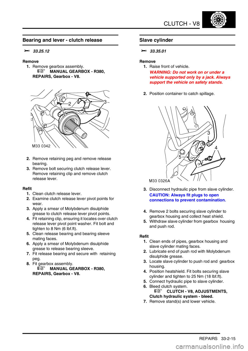
2.Remove retaining peg and remove release
bearing.
3.Remove bolt securing clutch release lever.
Remove retaining clip and remove clutch
release lever.
Refit
1.Clean clutch release lever.
2.Examine clutch release lever pivot points for
wear.
3.Apply a smear of Molybdenum disulphide
grease to clutch release lever pivot points.
4.Fit retaining clip, ensuring it locates over clutch
release lever pivot point washer. Fit bolt and
tighten to 8 Nm (6 lbf.ft).
5.Clean release bearing and bearing sleeve
mating faces.
6.Apply a smear of Molybdenum disulphide
grease to release bearing sleeve.
7.Fit release bearing and secure with retaining
peg.
8.Fit gearbox assembly.
+ MANUAL GEARBOX - R380,
REPAIRS, Gearbox - V8.
Slave cylinder
$% 33.35.01
Remove
1.Raise front of vehicle.
WARNING: Do not work on or under a
vehicle supported only by a jack. Always
support the vehicle on safety stands.
2.Position container to catch spillage.
3.Disconnect hydraulic pipe from slave cylinder.
CAUTION: Always fit plugs to open
connections to prevent contamination.
4.Remove 2 bolts securing slave cylinder to
gearbox housing and collect heat shield.
5.Withdraw slave cylinder from gearbox housing
and push rod.
Refit
1.Clean ends of pipes, gearbox housing and
slave cylinder mating faces.
2.Lubricate end of push rod with Molybdenum
disulphide grease.
3.Locate slave cylinder to push rod and gearbox
housing.
4.Position heatshield. Fit bolts securing slave
cylinder and tighten to 25 Nm (18 lbf.ft).
5.Connect hydraulic pipe to slave cylinder.
6.Bleed clutch system.
+ CLUTCH - V8, ADJUSTMENTS,
Clutch hydraulic system - bleed.
7.Remove stand(s) and lower vehicle.
Page 943 of 1672

FRONT SUSPENSION
60-4 DESCRIPTION AND OPERATION
Description
General
The front suspension comprises two dampers and coil springs, two radius arms, a Panhard rod and an anti-roll bar.
The front axle provides the location points for the dampers, springs, radius arms and the Panhard rod.
The anti-roll bar assembly is an essential part of the front suspension. On vehicles without Active Cornering
Enhancement (ACE) a conventional 'passive' anti-roll bar is fitted. On vehicles fitted with the ACE system, a thicker
diameter anti-roll bar, known as a torsion bar, is used with an actuator at one end.
+ FRONT SUSPENSION, DESCRIPTION AND OPERATION, Description - ACE.
The hydraulic dampers and coil springs provide springing for each front wheel. The long travel dampers, springs and
radius arms provide maximum axle articulation and wheel travel for off-road driving. The front axle is controlled
longitudinally by two forged steel radius arms and transversely by a Panhard rod.
Radius arms
Each radius arm is manufactured from forged steel. Two bushes are pressed into the forward end of the radius arm.
The forward end of the radius arm is located in a fabricated bracket on the axle and secured through the bushes with
two bolts and nuts. A bush is pressed into the rear of the radius arm which is also located in a fabricated bracket on
each chassis longitudinal and secured through the bush with a bolt and nut.
The radius arms prevent longitudinal movement of the front axle and because of their length allow maximum axle
articulation. The stiffness of the bushes in each radius arm also contributes to the vehicle roll stiffness.
Each radius arm has a notch on its lower edge which provides location for the vehicle jack.
Dampers
Two conventional telescopic dampers are used to control body/axle movement. A turret is located on a bracket welded
to the chassis. The upper spring seat has four studs which pass through holes in the bracket and align with
corresponding holes in the turret. Four nuts are screwed onto the studs and secure the turret and upper spring seat
to the chassis.
A fabricated platform is welded to the axle. The platform has two captive nuts which provide for the attachment of the
damper. A lower spring seat is located on the platform. Each spring seat is handed and has a bracket which secures
the ABS sensor harness and the front brake hose.
Each damper is fitted with a bush at its upper end. The bush locates in the top of the turret and is secured with a cross
bolt. The lower attachment point for the damper is also fitted with a bush. This bush has a spindle through its centre
with a hole at each end. The spindle is seated on the lower spring seat and the axle platform and secured with two
bolts. The coil spring is fitted in a compressed state between the upper and lower spring seats and assists the damper
in controlling the body/axle movement. The upper and lower bushes are replaceable items.
Rubber bump stops are fitted to the chassis above each end of the axle. The bump stops are progressive in their
compression and prevent the axle from contacting the chassis in the event of maximum suspension travel being
reached. The bump stops revert to their original shape once the compression load has been removed from them.
The damper functions by restricting the flow of a hydraulic fluid through internal galleries within the damper body. A
chromium plated rod moves axially within the damper. As the rod moves, its movement is limited by the flow of fluid
through the galleries thus providing damping of undulations in the terrain. The damper rod is sealed at its exit point
from the body to maintain fluid within the unit and prevent the ingress of dirt and moisture. The seal also acts as a
wiper to keep the rod outer diameter clean. A plastic shroud protects the rod and slides over the body as the damper
moves. The coil spring aids the damper to extend after being compressed and also aids the damping process.