service indicator LAND ROVER DISCOVERY 2002 Workshop Manual
[x] Cancel search | Manufacturer: LAND ROVER, Model Year: 2002, Model line: DISCOVERY, Model: LAND ROVER DISCOVERY 2002Pages: 1672, PDF Size: 46.1 MB
Page 33 of 1672

INTRODUCTION
01-4
HRW Heated Rear Window
HSLA High Strength Low Alloy
ht/HT High tension
IACV Idle Air Control Valve
IAT Intake Air Temperature
ICE In-Car Entertainment
i.dia. Internal diameter
IDM Intelligent Driver Module
IF Intermediate Frequency
in
3Cubic inch
ILT Inlet Throttle
IPW Injector Pulse Width
ISO International Organisation for
Standardisation
ITS Inflatable Tubular Structure
k Thousand
kg Kilogramme
kg/h Kilogrammes per hour
km Kilometre
km/h Kilometres per hour
kPa KiloPascal
KS Knock Sensor
lb(s) Pounds
lbf Pounds force
lbf.in Pounds force inches
lbf/in
2Pounds per square inch
lbf.ft Pounds force feet
λLambda
lc Low compression
LCD Liquid Crystal Display
LED Light Emitting Diode
LEV Low Emission Vehicle
LH Left-Hand
LHD Left-Hand Drive
LSM Light Switch Module
LVS Liquid Vapour Separator
mMetre
µMicro
MAF Mass Air Flow
MAP Manifold Absolute Pressure
MET Mechanical, Electrical and Trim
MFU Multi-Function Unit
MFL Multi-Function Logic
max. Maximum
MEMS Modular Engine Management
System
MIG Metal/Inert Gas
MIL Malfunction Indicator Lamp
MPa MegaPascal
MOSFET Metal Oxide Semiconductor Field
Effect Transistor
min. Minimum
- Minus (tolerance)
' Minute (angle)
mm Millimetre
mph Miles per hour MPi Multi-Point injection
MV Motorised Valve
MY Model Year
NAS North American Specification
(-) Negative (electrical)
Nm Newton metre
No. Number
NO
2Nitrogen Dioxide
NO
xOxides of Nitrogen
NTC Negative Temperature
Coefficient
NRV Non Return Valve
OBD On Board Diagnostics
OBM On Board Monitoring
o.dia. Outside diameter
OAT Organic Acid Technology
ORM Off-road Mode
ΩOhm
PAS Power Assisted Steering
PCB Printed Circuit Board
PCV Positive Crankcase Ventilation
PDC Parking Distance Control
PDOP Position Dilation Of Precision
PI Programme Information
PPS Pulse Per Second
PS Programme Service
psi Pounds per square inch
pts. Pints
% Percentage
+ Plus (tolerance) or Positive
(electrical)
±Plus or minus (tolerance)
PTC Positive Temperature Coefficient
PTFE Polytetrafluorethylene
PVC Polyvinyl chloride
PWM Pulse Width Modulation
RDS Radio Data Service
rRadius
:Ratio
ref Reference
REG Regionalisation
RES Rover Engineering Standards
rev/min Revolutions per minute
RF Radio Frequency
RGB Red / Green / Blue
RH Right-Hand
RHD Right-Hand Drive
ROM Read Only Memory
RON Research Octane Number
ROV Roll Over Valve
ROW Rest Of World
SAE Society of Automotive Engineers
SAI Secondary Air Injection
" Second (angle)
SLABS Self Levelling and Anti-Lock
Brake System
SLS Self Levelling Suspension
SOHC Single Overhead Camshaft
Page 356 of 1672

EMISSION CONTROL - V8
DESCRIPTION AND OPERATION 17-2-19
For NAS vehicles with positive pressure, EVAP system leak detection capability, the atmosphere vent line from the
EVAP canister connects to a port on the fuel leak detection pump via a short, large bore hose which is secured to the
component ports by crimped metal clips at each end. A large bore plastic hose from the top of the leak detection pump
is routed to the RH side of the engine bay where it connects to an air filter canister. Under normal operating conditions
(when the fuel leak detection solenoid valve is not energised), the EVAP canister is able to take in clean air via the
air filter, through the pipework and past the open solenoid valve to allow normal purge operation to take place and
release any build up of EVAP system pressure to atmosphere.
The EVAP system pipes are clipped at various points along the pipe runs and tied together with tie straps at suitable
points along the runs.
The NAS and ROW EVAP canisters are of similar appearance, but use charcoal of different consistency. The ROW
vehicles use granular charcoal of 11 bwc (butane working capacity) and NAS vehicles use pelletised charcoal with a
higher absorption capacity of 15 bwc. All canisters are of rectangular shape and have capacities of 1.8 litres (3 1/8
imp. pts) with purge foam retention.
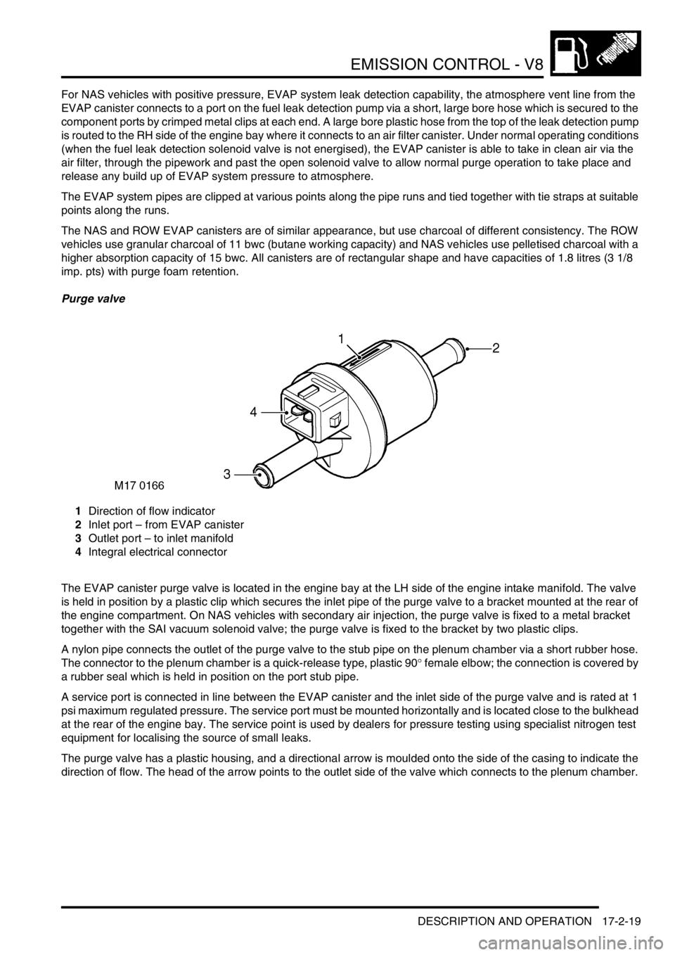
Purge valve
1Direction of flow indicator
2Inlet port – from EVAP canister
3Outlet port – to inlet manifold
4Integral electrical connector
The EVAP canister purge valve is located in the engine bay at the LH side of the engine intake manifold. The valve
is held in position by a plastic clip which secures the inlet pipe of the purge valve to a bracket mounted at the rear of
the engine compartment. On NAS vehicles with secondary air injection, the purge valve is fixed to a metal bracket
together with the SAI vacuum solenoid valve; the purge valve is fixed to the bracket by two plastic clips.
A nylon pipe connects the outlet of the purge valve to the stub pipe on the plenum chamber via a short rubber hose.
The connector to the plenum chamber is a quick-release type, plastic 90
° female elbow; the connection is covered by
a rubber seal which is held in position on the port stub pipe.
A service port is connected in line between the EVAP canister and the inlet side of the purge valve and is rated at 1
psi maximum regulated pressure. The service port must be mounted horizontally and is located close to the bulkhead
at the rear of the engine bay. The service point is used by dealers for pressure testing using specialist nitrogen test
equipment for localising the source of small leaks.
The purge valve has a plastic housing, and a directional arrow is moulded onto the side of the casing to indicate the
direction of flow. The head of the arrow points to the outlet side of the valve which connects to the plenum chamber.
Page 464 of 1672

ENGINE MANAGEMENT SYSTEM - V8
DESCRIPTION AND OPERATION 18-2-7
The ECM controls the following outputs:
lFuel injectors (1 per cylinder).
lIgnition coils/ high tension leads/ spark plugs.
lFuel pump relay.
lIdle air control valve.
lHeated oxygen sensors.
lEVAP canister purge valve.
lEVAP canister vent solenoid (CVS) valve (where fitted).
lMalfunction Indicator Lamp (MIL)/ service engine soon lamp (where fitted).
lHill descent control (via SLABS interface).
lEVAP system fuel leak detection pump (where fitted)
lSecondary air injection pump (where fitted)
The ECM also interfaces with the following:
lDiagnostics via diagnostic connector with TestBook.
lController Area Network (CAN) link to EAT ECU.
lAir conditioning system.
lSelf Levelling & Anti-lock Braking System (SLABS) ECU.
lImmobilisation system via the body control unit (BCU).
lInstrument cluster.
lCruise control ECU
lActive Cornering Enhancement (ACE) ECU
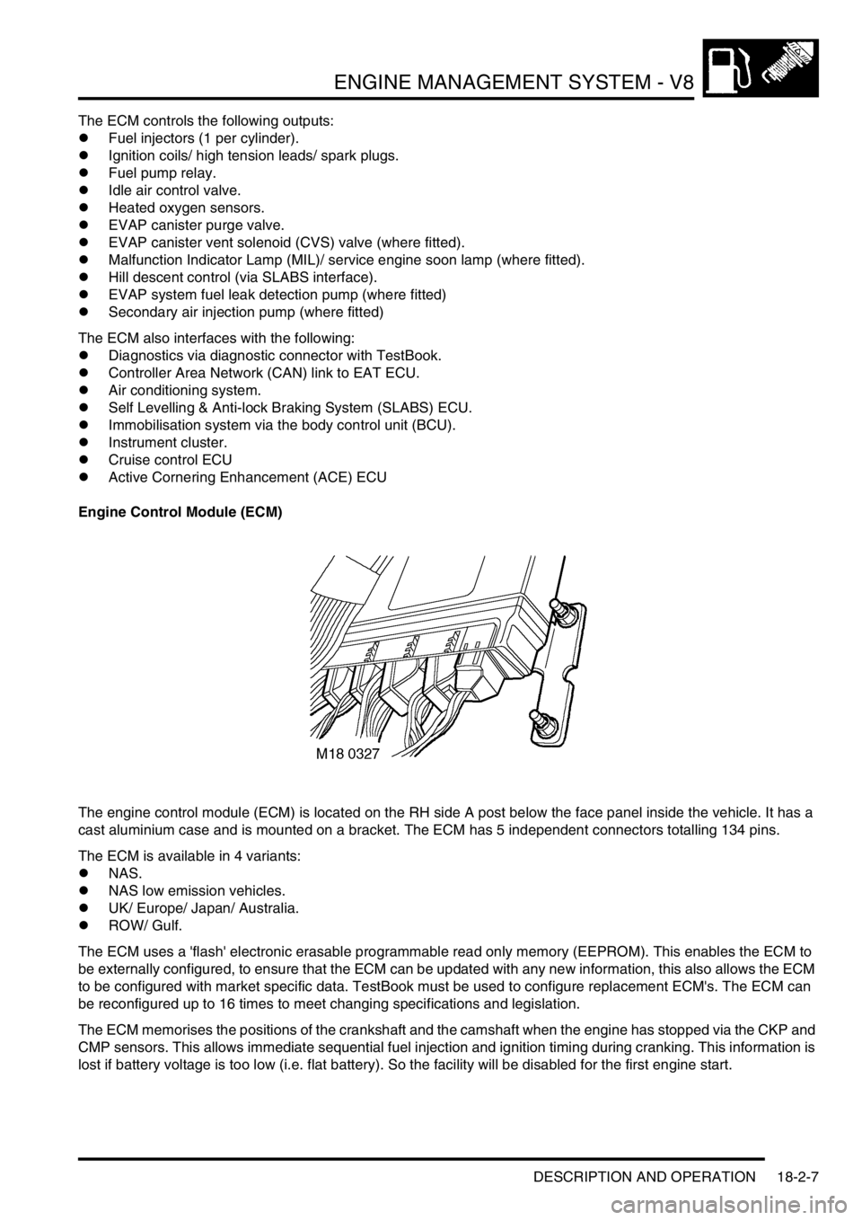
Engine Control Module (ECM)
The engine control module (ECM) is located on the RH side A post below the face panel inside the vehicle. It has a
cast aluminium case and is mounted on a bracket. The ECM has 5 independent connectors totalling 134 pins.
The ECM is available in 4 variants:
lNAS.
lNAS low emission vehicles.
lUK/ Europe/ Japan/ Australia.
lROW/ Gulf.
The ECM uses a 'flash' electronic erasable programmable read only memory (EEPROM). This enables the ECM to
be externally configured, to ensure that the ECM can be updated with any new information, this also allows the ECM
to be configured with market specific data. TestBook must be used to configure replacement ECM's. The ECM can
be reconfigured up to 16 times to meet changing specifications and legislation.
The ECM memorises the positions of the crankshaft and the camshaft when the engine has stopped via the CKP and
CMP sensors. This allows immediate sequential fuel injection and ignition timing during cranking. This information is
lost if battery voltage is too low (i.e. flat battery). So the facility will be disabled for the first engine start.
Page 496 of 1672

ENGINE MANAGEMENT SYSTEM - V8
DESCRIPTION AND OPERATION 18-2-39
Hill Decent Control (HDC)
Refer to Brakes for description of the hill descent control.
+ BRAKES, DESCRIPTION AND OPERATION, Description.
High/Low ratio switch
Refer to Transfer Box for description of the high/ low ratio switch transfer box components.
+ TRANSFER BOX - LT230SE, DESCRIPTION AND OPERATION, Description.
Malfunction Indicator Lamp (MIL)/ service engine soon warning lamp
The MIL/ service engine soon warning lamp is located in the instrument cluster. It illuminates to alert the driver to
system malfunctions. Service engine soon warning lamp is the name for this warning lamp in NAS only, it is called
MIL in all other markets.
During ignition a self-test function of the lamp is carried out. The lamp will illuminate for 3 seconds then it will
extinguish if no faults exist.
+ INSTRUMENTS, DESCRIPTION AND OPERATION, Description.
Input/Output
The MIL is supplied with battery voltage from the instrument cluster. When the ECM detects a fault, it provides an
earth path to illuminate the MIL. Output to the MIL is via pin 20 of connector C0637 of the ECM.
Page 931 of 1672

STEERING
57-44 REPAIRS
14.Position steering column assembly in a vice.
15.Remove 2 screws and remove ignition switch.
16.Remove cable tie and remove multiplug from
ignition switch.
17.Centre punch or drill out steering lock shear
bolts.
18.Remove steering lock
Refit
1.Position lock to steering column assembly and
fit shear bolts. Do not tighten shear bolts at this
stage.
2.Insert starter key, check operation of steering
lock and that key turns freely.
3.Tighten shear bolts fully and shear heads off.
4.Position ignition switch to column, fit and
tighten screws.
5.Position multiplug to switch and secure with
new cable tie.
6.Fit rubber boot to column.
7.Remove column from vice.
8.Position steering to fascia rail fit nuts and
tighten to 22 Nm (16 lbf.ft).
9.Secure harness to column clip.
10.Position rubber grommet.
11.Close access panel and secure turn buckles.
12.Connect ignition switch multiplugs.
13.Position column switch and tighten clamp
screw.
14.Connect column switch multiplugs.
15.Position passive coil, connect multiplug and
illumination bulb.
16.Fit steering column nacelle.
+ STEERING, REPAIRS, Nacelle -
steering column.
17.Fit rotary coupler.
+ RESTRAINT SYSTEMS, REPAIRS,
Rotary coupler.
18.Close fascia lower access panel.
19.Fit steering column intermediate shaft.
+ STEERING, REPAIRS, Shaft -
intermediate and universal joint - steering
column.
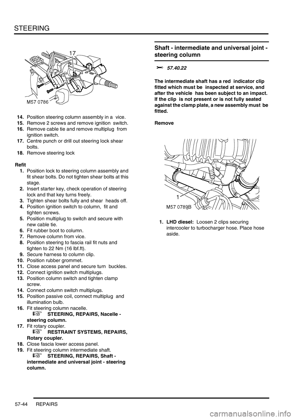
Shaft - intermediate and universal joint -
steering column
$% 57.40.22
The intermediate shaft has a red indicator clip
fitted which must be inspected at service, and
after the vehicle has been subject to an impact.
If the clip is not present or is not fully seated
against the clamp plate, a new assembly must be
fitted.
Remove
1. LHD diesel: Loosen 2 clips securing
intercooler to turbocharger hose. Place hose
aside.
Page 1484 of 1672

BODY CONTROL UNIT
DESCRIPTION AND OPERATION 86-3-15
The BCU controls the wiper motor frequency of operation via the IDM when intermittent wipe or wash is selected. The
front intermittent wipe option features five different intermittent delay periods. The shortest delay period is 3 seconds
and this is increased by 2 second increments up to a maximum delay of 11 seconds. The desired delay period for the
front wipers is set by the position of the rotary switch located on the wiper column stalk.
The rear wiper switch is located on the instrument pack cowl and is latched when pressed. The rear wiper electric
motor is located in the tail door. The rear wiper operation is controlled according to a programmed strategy via the
BCU and the IDM. The BCU also checks for a signal from either the reverse lamp switch located in the vehicle gearbox
(manual gearbox models) or the gear position switch (automatic gearbox models) for operating the rear wipers when
the vehicle is in reverse. The rear wiper and washer only operate when the ignition switch is in position II.
The front and rear washer pumps and the headlamp powerwash (where fitted) are also controlled through the BCU.
The washers are operated from electric pumps attached to the washer reservoir located in the left hand wheel arch.
The front wash switch is located on the wiper column stalk and is pulled towards the steering wheel to select the
washer function. When the front washers are operated, the wipers are also activated for three full cycles. The rear
wash switch is located on the instrument pack cowl. The BCU programme can be configured in one of two modes of
operation:
lNo wiper operation when the wash switch is pressed.
lWiper action after an initial delay of 400 ms.
Headlamp wash is activated by the BCU via the IDM and operates when the headlamps are on and the front washers
function is selected.
Electric seats
The BCU controls the logical operation of the electrically operated front seats. Two modes of operation are available:
+ SEATS, DESCRIPTION AND OPERATION, Description - electric seats.
lElectric seat adjustment is enabled if the ignition is on or the driver's door is opened for a short time period.
lElectric seat adjustment is enabled if the ignition is on and the driver's door is closed.
The seats are operated by four electric motors which control the seat cushion rear up/ down, the seat cushion front
up/ down, seat cushion forward/ rearward and seat squab recline. The electrically powered lumbar adjustment in each
seat is operated by a single motorised air pump and a solenoid located on the seat squab frame. The air pump inflates
a cushion in the seat squab and the solenoid operates a valve to deflate the cushion. The seat squab and cushion
may also contain heater elements to provide heated seat operation.
The switches for electrically operated seats are located either side of the centre console.
Direction indicators and hazard warning lamps
The direction indicator lamps are operated from a three position direction indicator switch on the left hand, steering
column stalk. The BCU only allows the lamps to work as direction indicators when the ignition switch is in position II.
The BCU also controls the lamps to operate as hazard warning lamps and as a visual warning for the anti-theft system,
in which cases all lamps flash simultaneously irrespective of the ignition switch position.
System control of the direction indicators and hazard warning lamps is provided by the BCU operating with the IDM
and two electronic relays located in the passenger compartment fuse box. The IDM and relays are integral parts of
the passenger compartment fuse box and cannot be serviced individually. The serial data bus is used for
communication of status and operation requests between the BCU, IDM and instrument pack.
The hazard warning lamps are operated from a latching pushbutton switch located on the fascia.
All direction indicator/ hazard warning lamp bulbs are rated at 5 Watts.
Page 1632 of 1672

INSTRUMENTS
DESCRIPTION AND OPERATION 88-5
Description
General
The instrument pack consists of four analogue dials, four warning lamp packs and a Liquid Crystal Display (LCD)
odometer.
The four dials are used to indicate:
lRoad speed.
lEngine speed.
lFuel tank level.
lEngine coolant temperature.
The dials are driven by a microprocessor from information received from the serial communication link. Information
input is received as either:
lDigital.
lAnalogue.
lPulse train.
lPulse Width Modulation (PWM).
The LCD provides information for:
lOdometer.
lTrip distance.
lSelected gear (on vehicles fitted with an automatic gearbox).
A trip reset button is provided to zero the trip display, this button also allows the selection of "miles" or "kilometres"
for the display. A photocell controls the illumination of the LCD, maintaining contrast of the display during ambient light
changes.
Within the four warning lamp packs there are 28 lamps. A long life bulb illuminates the high beam warning lamp and
the rest of the warning lamps are illuminated by Light Emitting Diodes (LED's). All warning lamp legends are invisible
until lit. When lit the symbols are illuminated on a black background.
The warning lamps illuminate in one of four colours. The colour indicates the level of importance to the driver, as
follows:
lRed = warning.
lAmber = caution.
lGreen = system operative.
lBlue = main beam operative.
The first warning lamp pack is located in the top left-hand side of the instrument pack and contains the following
warning lamps:
lTraction control warning lamp.
lTransfer box in neutral warning lamp.
lDifferential lock warning lamp
lOverspeed warning lamp (activated for gulf market only).
lBrake system warning lamp.
lHill Descent Control (HDC) information warning lamp.
lMalfunction Indicator Lamp (MIL)/ SERVICE ENGINE SOON warning lamp.
The second warning lamp pack is located in the centre of the instrument pack and contains the following warning
lamps:
lDirection indicator warning lamps.
lHigh beam warning lamp.
lAnti-lock brake system warning lamp.
Page 1639 of 1672

INSTRUMENTS
88-12 DESCRIPTION AND OPERATION
Malfunction Indicator Lamp (MIL)/ SERVICE ENGINE SOON warning lamp
The MIL/service engine soon warning lamp within the instrument pack utilises an amber LED and a clear legend. If
an emission related fault is detected by the engine management system or, on automatic gearbox models, the EAT
ECU, the ECM will illuminate the LED providing the driver with a visible warning.
The warning lamp will illuminate whenever the vehicle is driven until the fault is repaired, and the ECM fault code
memory is cleared using TestBook.
When the ignition is switch on the ECM carries out a self-test function of the lamp. The lamp will illuminate for 3
seconds then extinguish if no faults exist. If a fault is present the lamp will be extinguished for 1 second before
illuminating again to indicate a fault exists.
There are two configurations of the legend for the warning lamp:
lNAS and Canada = SERVICE ENGINE SOON text.
lAll other markets = MIL SAE J1930 symbol.
The power input for the LED is supplied by the instrument pack via fuse 27. The ECM provides a voltage to the
instrument pack Central Processing Unit (CPU) to control the warning lamp:
l< 1.8 volts = warning lamp on.
l> 7.7 volts = warning lamp off.