handbrake LAND ROVER FREELANDER 2001 User Guide
[x] Cancel search | Manufacturer: LAND ROVER, Model Year: 2001, Model line: FREELANDER, Model: LAND ROVER FREELANDER 2001Pages: 1007, PDF Size: 23.47 MB
Page 491 of 1007
REAR AXLE & FINAL DRIVE
51-6 REPAIRS
Refit
1.Fit new collapsible spacer.
2.Fit pinion bearing and oil thrower.
3.Clean pinion flange and oil seal recess.
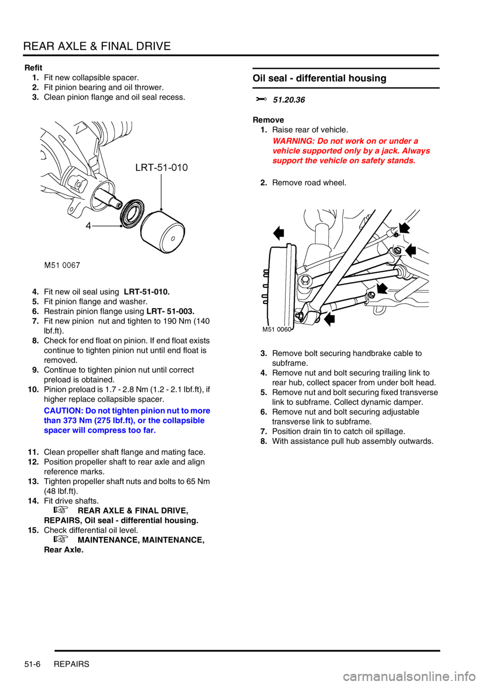
4.Fit new oil seal using LRT-51-010.
5.Fit pinion flange and washer.
6.Restrain pinion flange using LRT- 51-003.
7.Fit new pinion nut and tighten to 190 Nm (140
lbf.ft).
8.Check for end float on pinion. If end float exists
continue to tighten pinion nut until end float is
removed.
9.Continue to tighten pinion nut until correct
preload is obtained.
10.Pinion preload is 1.7 - 2.8 Nm (1.2 - 2.1 lbf.ft), if
higher replace collapsible spacer.
CAUTION: Do not tighten pinion nut to more
than 373 Nm (275 lbf.ft), or the collapsible
spacer will compress too far.
11.Clean propeller shaft flange and mating face.
12.Position propeller shaft to rear axle and align
reference marks.
13.Tighten propeller shaft nuts and bolts to 65 Nm
(48 lbf.ft).
14.Fit drive shafts.
+ REAR AXLE & FINAL DRIVE,
REPAIRS, Oil seal - differential housing.
15.Check differential oil level.
+ MAINTENANCE, MAINTENANCE,
Rear Axle.
Oil seal - differential housing
$% 51.20.36
Remove
1.Raise rear of vehicle.
WARNING: Do not work on or under a
vehicle supported only by a jack. Always
support the vehicle on safety stands.
2.Remove road wheel.
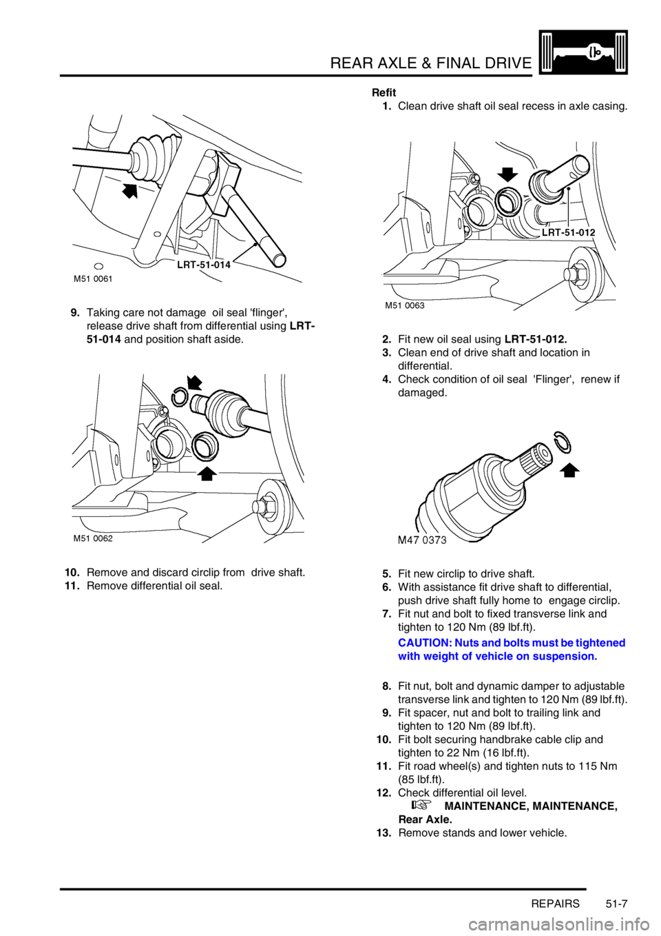
3.Remove bolt securing handbrake cable to
subframe.
4.Remove nut and bolt securing trailing link to
rear hub, collect spacer from under bolt head.
5.Remove nut and bolt securing fixed transverse
link to subframe. Collect dynamic damper.
6.Remove nut and bolt securing adjustable
transverse link to subframe.
7.Position drain tin to catch oil spillage.
8.With assistance pull hub assembly outwards.
Page 492 of 1007
REAR AXLE & FINAL DRIVE
REPAIRS 51-7
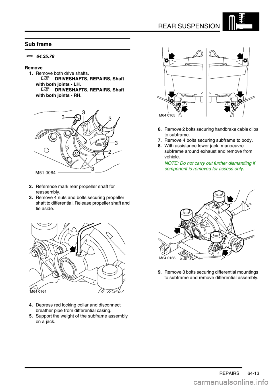
9.Taking care not damage oil seal 'flinger',
release drive shaft from differential using LRT-
51-014 and position shaft aside.
10.Remove and discard circlip from drive shaft.
11.Remove differential oil seal.Refit
1.Clean drive shaft oil seal recess in axle casing.
2.Fit new oil seal using LRT-51-012.
3.Clean end of drive shaft and location in
differential.
4.Check condition of oil seal 'Flinger', renew if
damaged.
5.Fit new circlip to drive shaft.
6.With assistance fit drive shaft to differential,
push drive shaft fully home to engage circlip.
7.Fit nut and bolt to fixed transverse link and
tighten to 120 Nm (89 lbf.ft).
CAUTION: Nuts and bolts must be tightened
with weight of vehicle on suspension.
8.Fit nut, bolt and dynamic damper to adjustable
transverse link and tighten to 120 Nm (89 lbf.ft).
9.Fit spacer, nut and bolt to trailing link and
tighten to 120 Nm (89 lbf.ft).
10.Fit bolt securing handbrake cable clip and
tighten to 22 Nm (16 lbf.ft).
11.Fit road wheel(s) and tighten nuts to 115 Nm
(85 lbf.ft).
12.Check differential oil level.
+ MAINTENANCE, MAINTENANCE,
Rear Axle.
13.Remove stands and lower vehicle.
Page 537 of 1007

REAR SUSPENSION
64-2 REPAIRS
Bearing - hub
$% 64.15.14
Remove
1.Raise rear of vehicle.
WARNING: Do not work on or under a
vehicle supported only by a jack. Always
support the vehicle on safety stands.
2.Remove road wheel.
3.With assistant depressing the brake pedal,
remove and discard drive shaft nut.
4.Remove brake shoe assembly.
+ BRAKES, REPAIRS, Brake Shoes -
rear set.
5.Using LRT-70-007 release handbrake cable
from backplate and remove from backplate.6.Remove clip securing brake hose to bracket on
damper.
7.Disconnect brake pipe union from wheel
cylinder.
CAUTION: Always fit plugs to open
connections to prevent contamination.
8.Release ABS sensor from hub.
9.Remove nut and bolt securing trailing link to
hub.
10.Remove nut, bolt and washers securing
transverse links to hub.
11.Remove 2 nuts and bolts securing hub to
damper.
12.Release damper from hub.
13.Remove hub assembly from drive shaft.
NOTE: Do not carry out further dismantling if
component is removed for access only.
Page 540 of 1007

REAR SUSPENSION
REPAIRS 64-5
7.Fit hub to damper and tighten bolts to 205 Nm
(151 lbf.ft).
CAUTION: Nuts and bolts must be tightened
with weight of vehicle on suspension.
8.Fit nut, bolt and washers securing transverse
links to hub and tighten nut to 105 Nm (77 lbf.ft).
9.Fit trailing link to hub and tighten nut and bolt to
120 Nm (89 lbf.ft).
NOTE: Ensure that washers are fitted to both
ends of bolts
10.Clean ABS sensor, smear sensor with an anti-
seize grease and fit sensor to hub.
CAUTION: Ensure ABS sensor is fully
located into hub, so that sensor touches
pole wheel teeth.
11.Fit brake pipe to wheel cylinder and tighten
union to 14 Nm (10 lbf.ft).
12.Fit clip securing brakepipe to bracket.
13.Fit and secure handbrake cable to backplate.
14.Fit brake shoes.
+ BRAKES, REPAIRS, Brake Shoes -
rear set.
15.Fit new drive shaft nut and tighten to 400 Nm
(295 lbf.ft). Stake nut to shaft.
16.Bleed brakes.
+ BRAKES, ADJUSTMENTS, Brake
bleed.
17.Fit road wheel(s) and tighten nuts to 115 Nm
(85 lbf.ft).
18.Remove stands and lower vehicle.
Damper
$% 64.30.02
Remove
1.Raise rear of vehicle.
WARNING: Do not work on or under a
vehicle supported only by a jack. Always
support the vehicle on safety stands.
2.Remove road wheel.
3.Clamp brake hose to prevent fluid loss.
4.Position absorbent cloth to catch spillage.
5.Loosen brake pipe union to hose and release
union.
CAUTION: Always fit plugs to open
connections to prevent contamination.
6.Remove clip securing brake hose to bracket on
damper. Release brake hose from bracket.
7.Release ABS sensor harness and brake hose
from damper.
8.Release ABS sensor from hub.
Page 548 of 1007
REAR SUSPENSION
REPAIRS 64-13
Sub frame
$% 64.35.78
Remove
1.Remove both drive shafts.
+ DRIVESHAFTS, REPAIRS, Shaft
with both joints - LH.
+ DRIVESHAFTS, REPAIRS, Shaft
with both joints - RH.
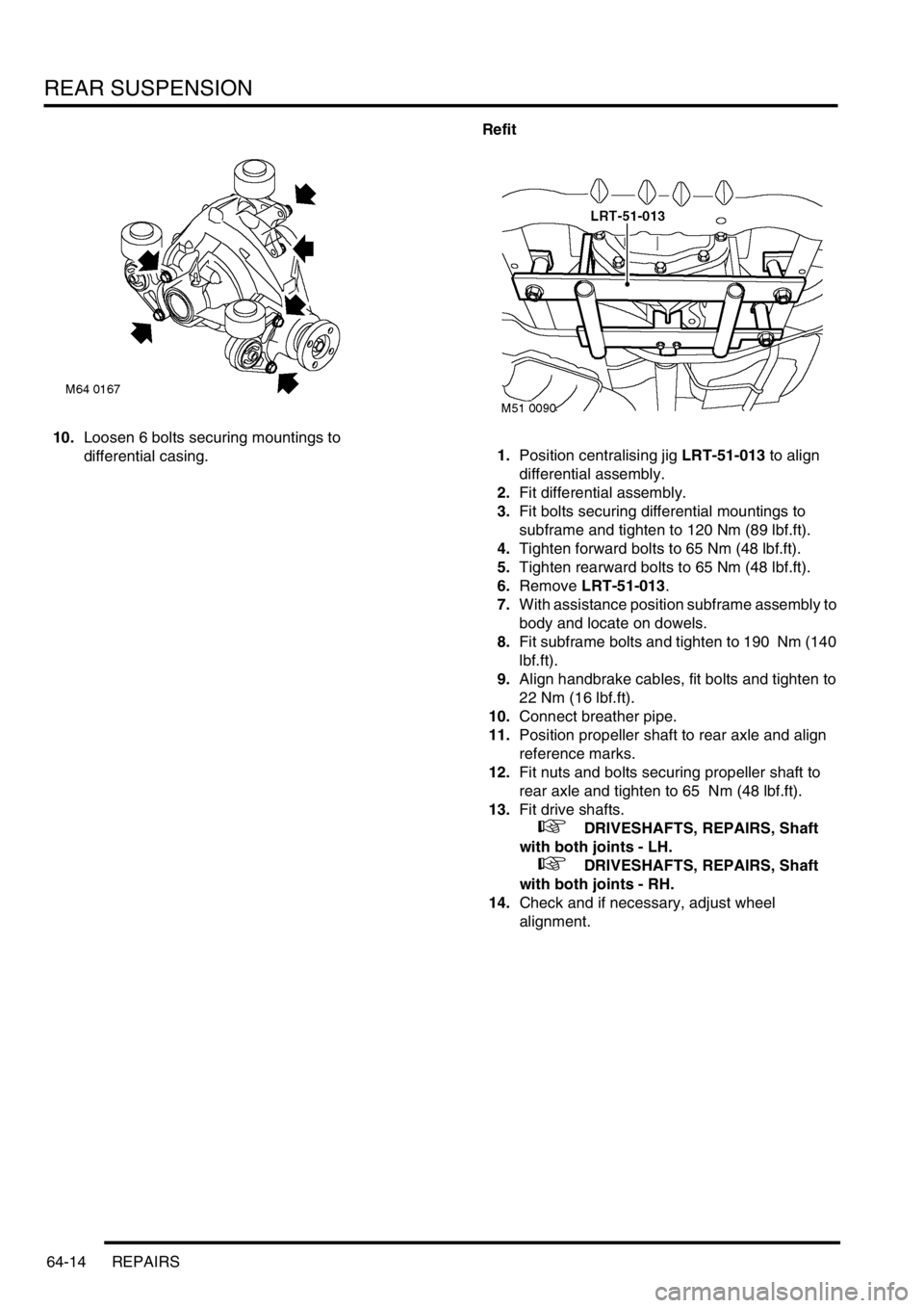
2.Reference mark rear propeller shaft for
reassembly.
3.Remove 4 nuts and bolts securing propeller
shaft to differential. Release propeller shaft and
tie aside.
4.Depress red locking collar and disconnect
breather pipe from differential casing.
5.Support the weight of the subframe assembly
on a jack.6.Remove 2 bolts securing handbrake cable clips
to subframe.
7.Remove 4 bolts securing subframe to body.
8.With assistance lower jack, manoeuvre
subframe around exhaust and remove from
vehicle.
NOTE: Do not carry out further dismantling if
component is removed for access only.
9.Remove 3 bolts securing differential mountings
to subframe and remove differential assembly.
Page 549 of 1007
REAR SUSPENSION
64-14 REPAIRS
10.Loosen 6 bolts securing mountings to
differential casing.Refit
1.Position centralising jig LRT-51-013 to align
differential assembly.
2.Fit differential assembly.
3.Fit bolts securing differential mountings to
subframe and tighten to 120 Nm (89 lbf.ft).
4.Tighten forward bolts to 65 Nm (48 lbf.ft).
5.Tighten rearward bolts to 65 Nm (48 lbf.ft).
6.Remove LRT-51-013.
7.With assistance position subframe assembly to
body and locate on dowels.
8.Fit subframe bolts and tighten to 190 Nm (140
lbf.ft).
9.Align handbrake cables, fit bolts and tighten to
22 Nm (16 lbf.ft).
10.Connect breather pipe.
11.Position propeller shaft to rear axle and align
reference marks.
12.Fit nuts and bolts securing propeller shaft to
rear axle and tighten to 65 Nm (48 lbf.ft).
13.Fit drive shafts.
+ DRIVESHAFTS, REPAIRS, Shaft
with both joints - LH.
+ DRIVESHAFTS, REPAIRS, Shaft
with both joints - RH.
14.Check and if necessary, adjust wheel
alignment.
Page 551 of 1007
BRAKES
70-2 ADJUSTMENTS
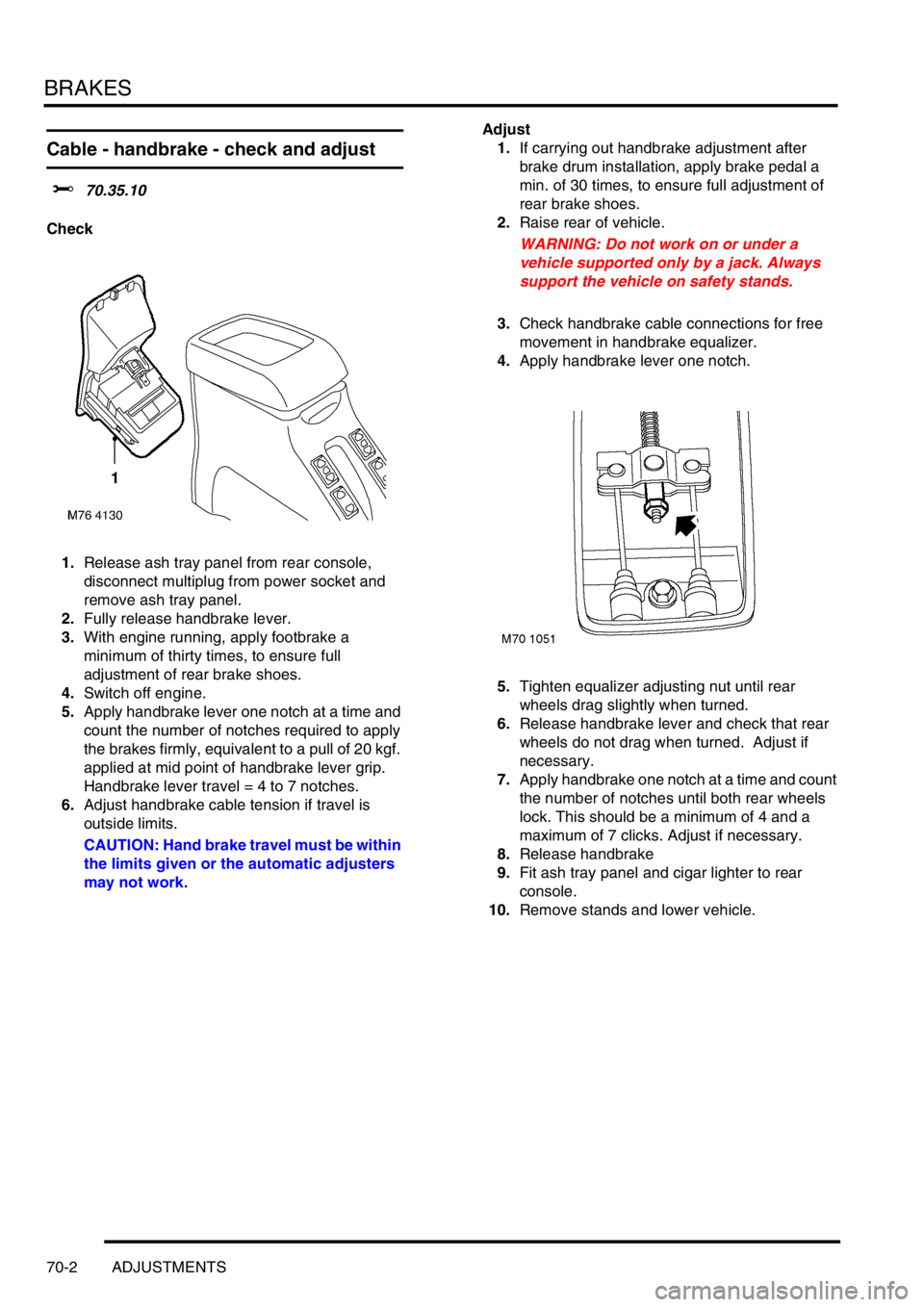
Cable - handbrake - check and adjust
$% 70.35.10
Check
1.Release ash tray panel from rear console,
disconnect multiplug from power socket and
remove ash tray panel.
2.Fully release handbrake lever.
3.With engine running, apply footbrake a
minimum of thirty times, to ensure full
adjustment of rear brake shoes.
4.Switch off engine.
5.Apply handbrake lever one notch at a time and
count the number of notches required to apply
the brakes firmly, equivalent to a pull of 20 kgf.
applied at mid point of handbrake lever grip.
Handbrake lever travel = 4 to 7 notches.
6.Adjust handbrake cable tension if travel is
outside limits.
CAUTION: Hand brake travel must be within
the limits given or the automatic adjusters
may not work.Adjust
1.If carrying out handbrake adjustment after
brake drum installation, apply brake pedal a
min. of 30 times, to ensure full adjustment of
rear brake shoes.
2.Raise rear of vehicle.
WARNING: Do not work on or under a
vehicle supported only by a jack. Always
support the vehicle on safety stands.
3.Check handbrake cable connections for free
movement in handbrake equalizer.
4.Apply handbrake lever one notch.
5.Tighten equalizer adjusting nut until rear
wheels drag slightly when turned.
6.Release handbrake lever and check that rear
wheels do not drag when turned. Adjust if
necessary.
7.Apply handbrake one notch at a time and count
the number of notches until both rear wheels
lock. This should be a minimum of 4 and a
maximum of 7 clicks. Adjust if necessary.
8.Release handbrake
9.Fit ash tray panel and cigar lighter to rear
console.
10.Remove stands and lower vehicle.
Page 552 of 1007
BRAKES
REPAIRS 70-3
REPAIRS
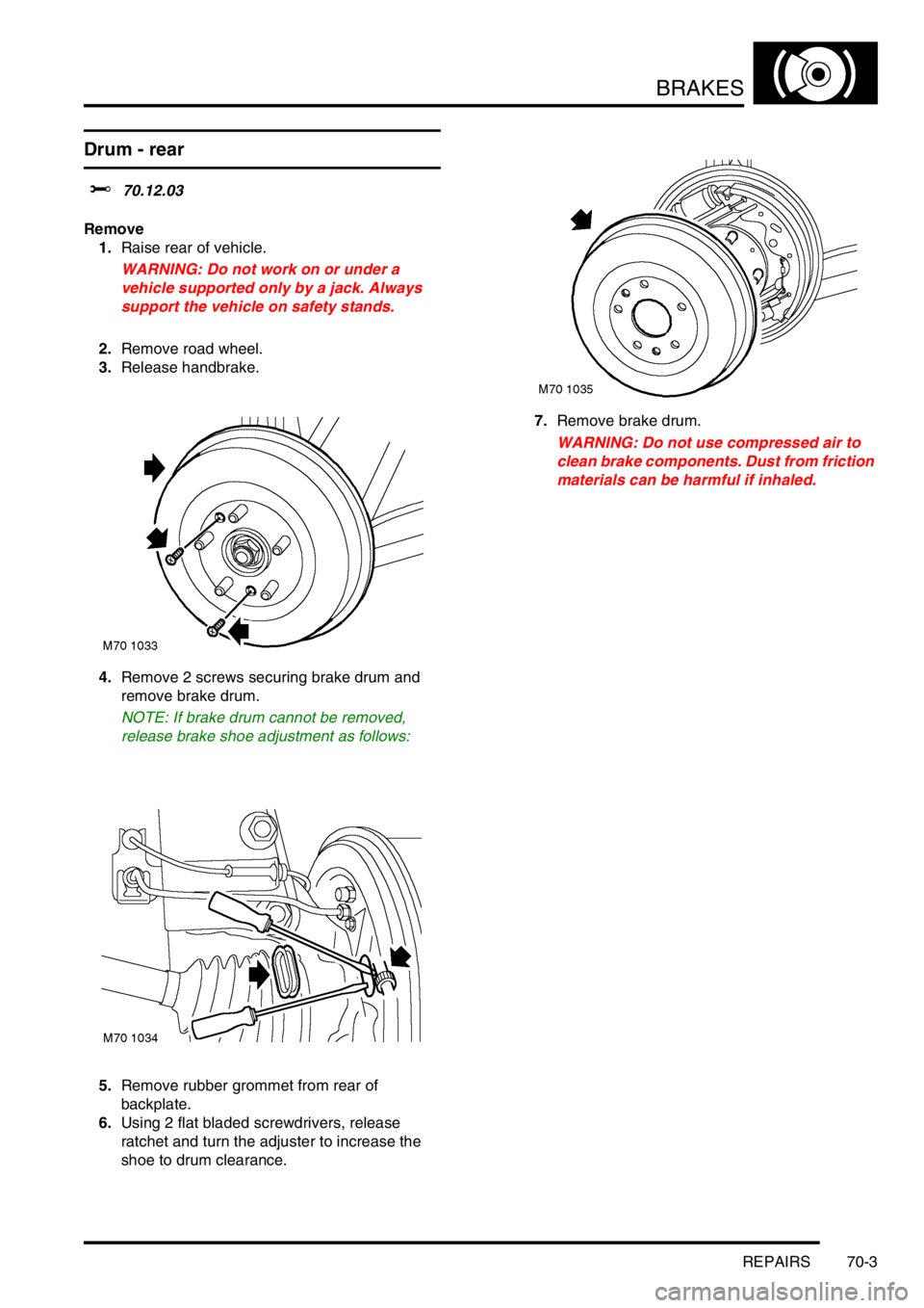
Drum - rear
$% 70.12.03
Remove
1.Raise rear of vehicle.
WARNING: Do not work on or under a
vehicle supported only by a jack. Always
support the vehicle on safety stands.
2.Remove road wheel.
3.Release handbrake.
4.Remove 2 screws securing brake drum and
remove brake drum.
NOTE: If brake drum cannot be removed,
release brake shoe adjustment as follows:
5.Remove rubber grommet from rear of
backplate.
6.Using 2 flat bladed screwdrivers, release
ratchet and turn the adjuster to increase the
shoe to drum clearance.7.Remove brake drum.
WARNING: Do not use compressed air to
clean brake components. Dust from friction
materials can be harmful if inhaled.
Page 553 of 1007
BRAKES
70-4 REPAIRS
Refit
1.Renew brake drum if scored, grooved or
cracked.
2.Check wheel cylinder pistons for freedom of
movement.
3.Clean backplate and brake drum with brake
cleaning fluid.
WARNING: Do not use petroleum based
fluid as damage will occur to rubber
components
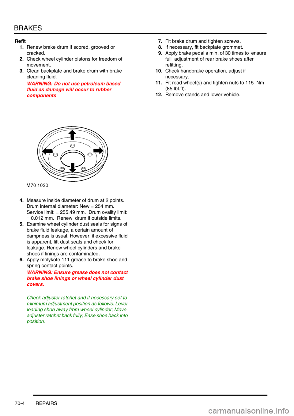
4.Measure inside diameter of drum at 2 points.
Drum internal diameter: New = 254 mm.
Service limit: = 255.49 mm. Drum ovality limit:
= 0.012 mm. Renew drum if outside limits.
5.Examine wheel cylinder dust seals for signs of
brake fluid leakage, a certain amount of
dampness is usual. However, if excessive fluid
is apparent, lift dust seals and check for
leakage. Renew wheel cylinders and brake
shoes if linings are contaminated.
6.Apply molykote 111 grease to brake shoe and
spring contact points.
WARNING: Ensure grease does not contact
brake shoe linings or wheel cylinder dust
covers.
Check adjuster ratchet and if necessary set to
minimum adjustment position as follows: Lever
leading shoe away from wheel cylinder; Move
adjuster ratchet back fully; Ease shoe back into
position.7.Fit brake drum and tighten screws.
8.If necessary, fit backplate grommet.
9.Apply brake pedal a min. of 30 times to ensure
full adjustment of rear brake shoes after
refitting.
10.Check handbrake operation, adjust if
necessary.
11.Fit road wheel(s) and tighten nuts to 115 Nm
(85 lbf.ft).
12.Remove stands and lower vehicle.
Page 559 of 1007
BRAKES
70-10 REPAIRS
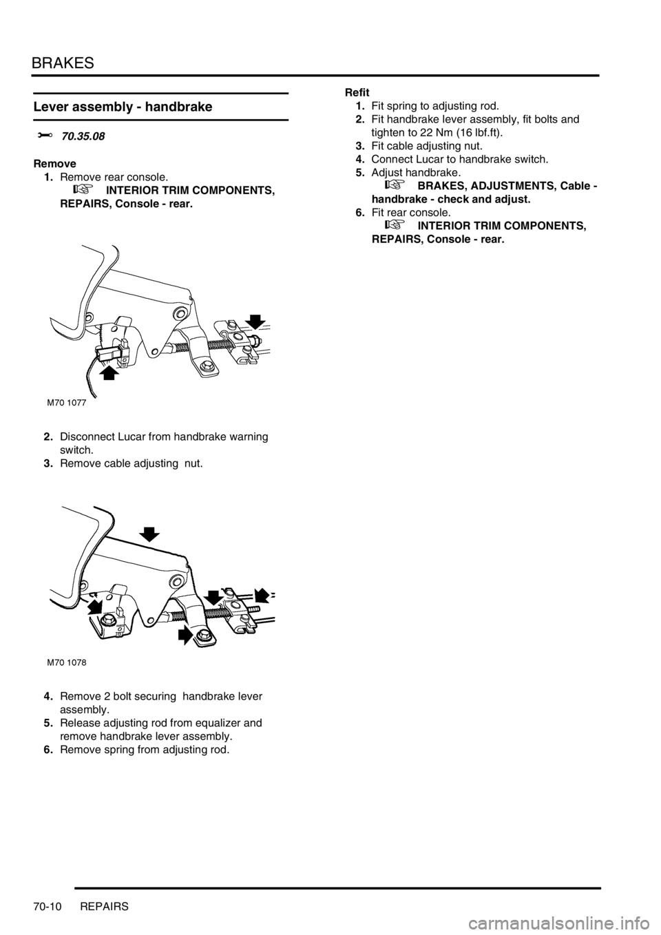
Lever assembly - handbrake
$% 70.35.08
Remove
1.Remove rear console.
+ INTERIOR TRIM COMPONENTS,
REPAIRS, Console - rear.
2.Disconnect Lucar from handbrake warning
switch.
3.Remove cable adjusting nut.
4.Remove 2 bolt securing handbrake lever
assembly.
5.Release adjusting rod from equalizer and
remove handbrake lever assembly.
6.Remove spring from adjusting rod.Refit
1.Fit spring to adjusting rod.
2.Fit handbrake lever assembly, fit bolts and
tighten to 22 Nm (16 lbf.ft).
3.Fit cable adjusting nut.
4.Connect Lucar to handbrake switch.
5.Adjust handbrake.
+ BRAKES, ADJUSTMENTS, Cable -
handbrake - check and adjust.
6.Fit rear console.
+ INTERIOR TRIM COMPONENTS,
REPAIRS, Console - rear.