differential LAND ROVER FREELANDER 2001 Owner's Manual
[x] Cancel search | Manufacturer: LAND ROVER, Model Year: 2001, Model line: FREELANDER, Model: LAND ROVER FREELANDER 2001Pages: 1007, PDF Size: 23.47 MB
Page 490 of 1007
REAR AXLE & FINAL DRIVE
REPAIRS 51-5
Oil seal - pinion
$% 51.20.01
Remove
1.Release both drive shafts from differential
assembly.
+ REAR AXLE & FINAL DRIVE,
REPAIRS, Oil seal - differential housing.
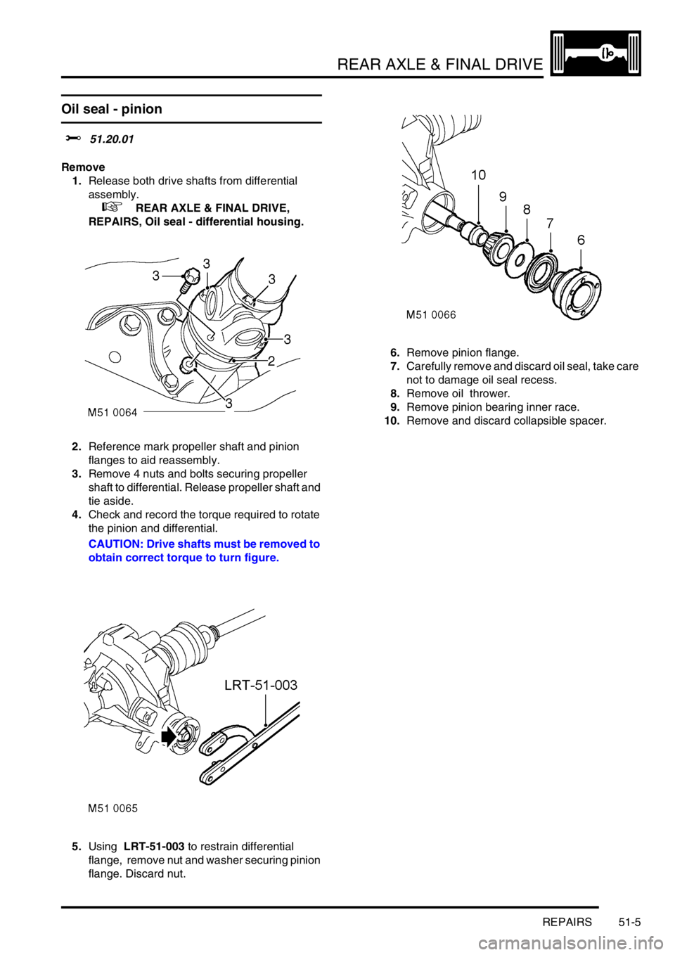
2.Reference mark propeller shaft and pinion
flanges to aid reassembly.
3.Remove 4 nuts and bolts securing propeller
shaft to differential. Release propeller shaft and
tie aside.
4.Check and record the torque required to rotate
the pinion and differential.
CAUTION: Drive shafts must be removed to
obtain correct torque to turn figure.
5.Using LRT-51-003 to restrain differential
flange, remove nut and washer securing pinion
flange. Discard nut.6.Remove pinion flange.
7.Carefully remove and discard oil seal, take care
not to damage oil seal recess.
8.Remove oil thrower.
9.Remove pinion bearing inner race.
10.Remove and discard collapsible spacer.
Page 491 of 1007
REAR AXLE & FINAL DRIVE
51-6 REPAIRS
Refit
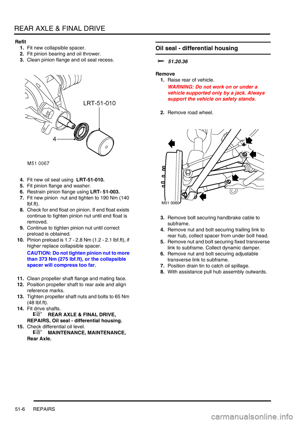
1.Fit new collapsible spacer.
2.Fit pinion bearing and oil thrower.
3.Clean pinion flange and oil seal recess.
4.Fit new oil seal using LRT-51-010.
5.Fit pinion flange and washer.
6.Restrain pinion flange using LRT- 51-003.
7.Fit new pinion nut and tighten to 190 Nm (140
lbf.ft).
8.Check for end float on pinion. If end float exists
continue to tighten pinion nut until end float is
removed.
9.Continue to tighten pinion nut until correct
preload is obtained.
10.Pinion preload is 1.7 - 2.8 Nm (1.2 - 2.1 lbf.ft), if
higher replace collapsible spacer.
CAUTION: Do not tighten pinion nut to more
than 373 Nm (275 lbf.ft), or the collapsible
spacer will compress too far.
11.Clean propeller shaft flange and mating face.
12.Position propeller shaft to rear axle and align
reference marks.
13.Tighten propeller shaft nuts and bolts to 65 Nm
(48 lbf.ft).
14.Fit drive shafts.
+ REAR AXLE & FINAL DRIVE,
REPAIRS, Oil seal - differential housing.
15.Check differential oil level.
+ MAINTENANCE, MAINTENANCE,
Rear Axle.
Oil seal - differential housing
$% 51.20.36
Remove
1.Raise rear of vehicle.
WARNING: Do not work on or under a
vehicle supported only by a jack. Always
support the vehicle on safety stands.
2.Remove road wheel.
3.Remove bolt securing handbrake cable to
subframe.
4.Remove nut and bolt securing trailing link to
rear hub, collect spacer from under bolt head.
5.Remove nut and bolt securing fixed transverse
link to subframe. Collect dynamic damper.
6.Remove nut and bolt securing adjustable
transverse link to subframe.
7.Position drain tin to catch oil spillage.
8.With assistance pull hub assembly outwards.
Page 492 of 1007
REAR AXLE & FINAL DRIVE
REPAIRS 51-7
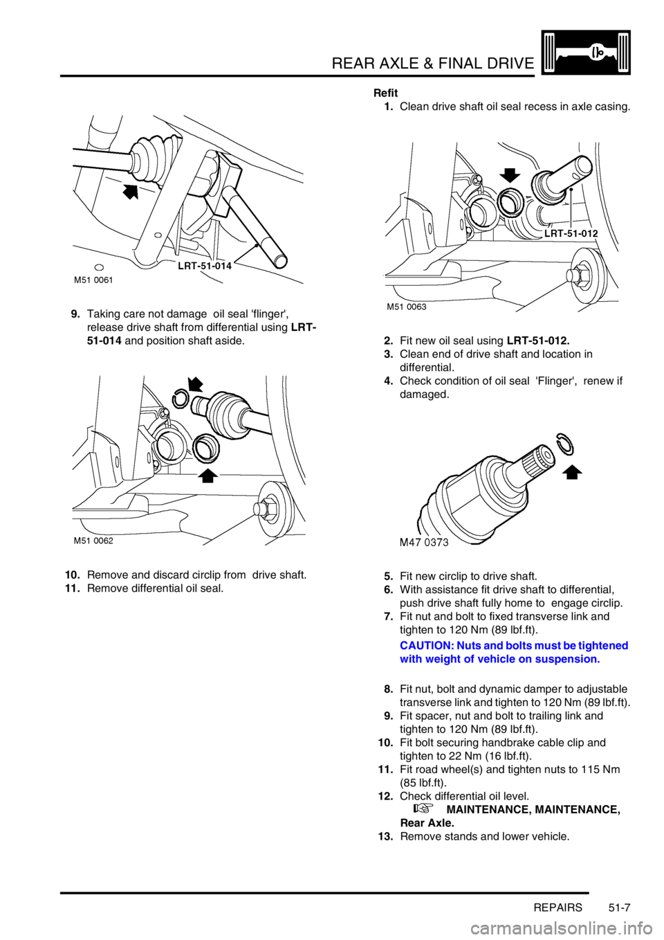
9.Taking care not damage oil seal 'flinger',
release drive shaft from differential using LRT-
51-014 and position shaft aside.
10.Remove and discard circlip from drive shaft.
11.Remove differential oil seal.Refit
1.Clean drive shaft oil seal recess in axle casing.
2.Fit new oil seal using LRT-51-012.
3.Clean end of drive shaft and location in
differential.
4.Check condition of oil seal 'Flinger', renew if
damaged.
5.Fit new circlip to drive shaft.
6.With assistance fit drive shaft to differential,
push drive shaft fully home to engage circlip.
7.Fit nut and bolt to fixed transverse link and
tighten to 120 Nm (89 lbf.ft).
CAUTION: Nuts and bolts must be tightened
with weight of vehicle on suspension.
8.Fit nut, bolt and dynamic damper to adjustable
transverse link and tighten to 120 Nm (89 lbf.ft).
9.Fit spacer, nut and bolt to trailing link and
tighten to 120 Nm (89 lbf.ft).
10.Fit bolt securing handbrake cable clip and
tighten to 22 Nm (16 lbf.ft).
11.Fit road wheel(s) and tighten nuts to 115 Nm
(85 lbf.ft).
12.Check differential oil level.
+ MAINTENANCE, MAINTENANCE,
Rear Axle.
13.Remove stands and lower vehicle.
Page 548 of 1007
REAR SUSPENSION
REPAIRS 64-13
Sub frame
$% 64.35.78
Remove
1.Remove both drive shafts.
+ DRIVESHAFTS, REPAIRS, Shaft
with both joints - LH.
+ DRIVESHAFTS, REPAIRS, Shaft
with both joints - RH.
2.Reference mark rear propeller shaft for
reassembly.
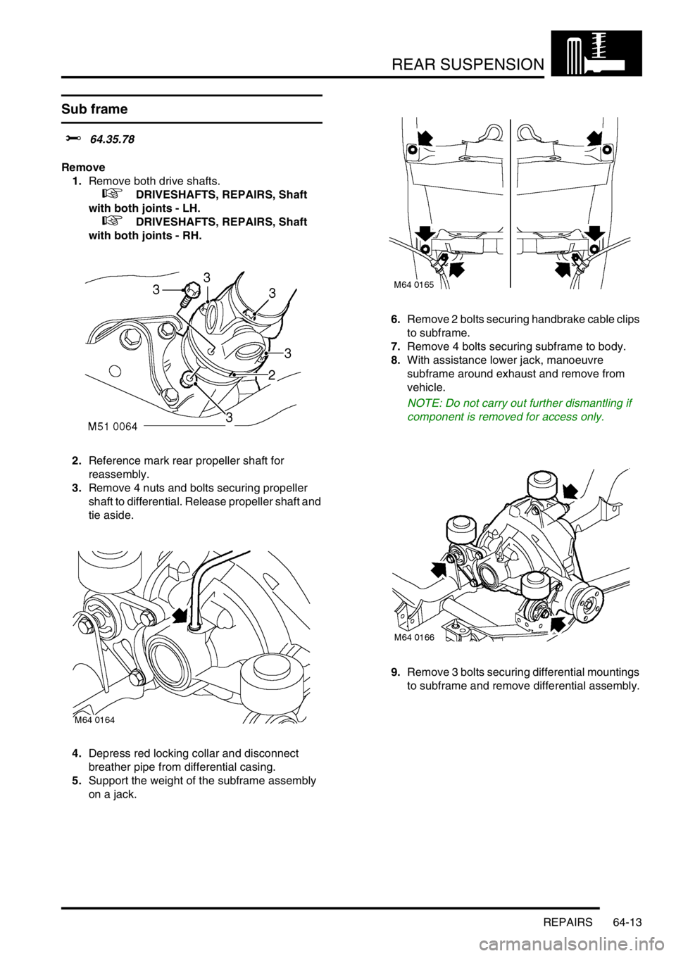
3.Remove 4 nuts and bolts securing propeller
shaft to differential. Release propeller shaft and
tie aside.
4.Depress red locking collar and disconnect
breather pipe from differential casing.
5.Support the weight of the subframe assembly
on a jack.6.Remove 2 bolts securing handbrake cable clips
to subframe.
7.Remove 4 bolts securing subframe to body.
8.With assistance lower jack, manoeuvre
subframe around exhaust and remove from
vehicle.
NOTE: Do not carry out further dismantling if
component is removed for access only.
9.Remove 3 bolts securing differential mountings
to subframe and remove differential assembly.
Page 549 of 1007
REAR SUSPENSION
64-14 REPAIRS
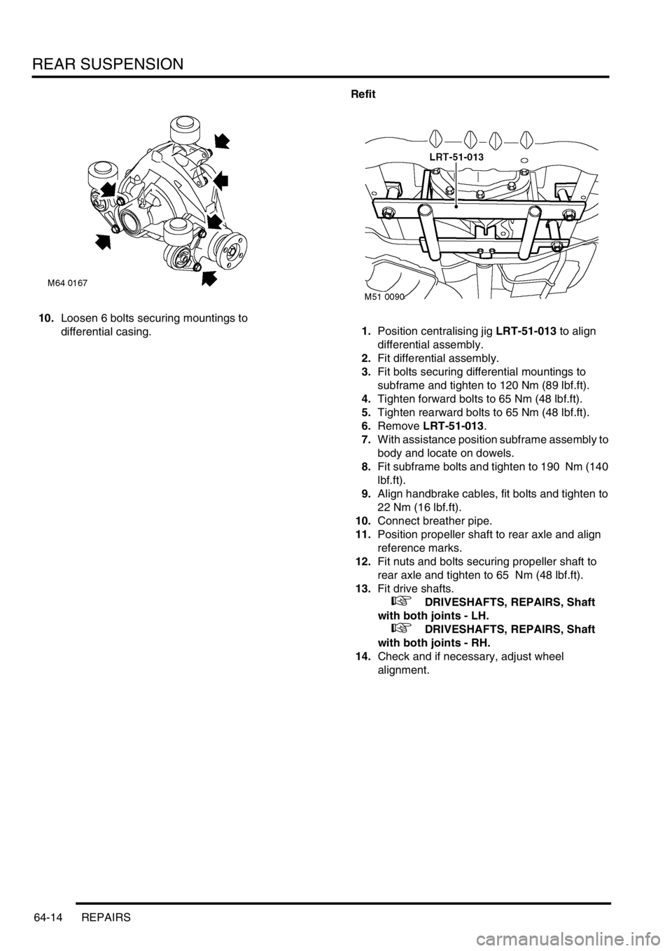
10.Loosen 6 bolts securing mountings to
differential casing.Refit
1.Position centralising jig LRT-51-013 to align
differential assembly.
2.Fit differential assembly.
3.Fit bolts securing differential mountings to
subframe and tighten to 120 Nm (89 lbf.ft).
4.Tighten forward bolts to 65 Nm (48 lbf.ft).
5.Tighten rearward bolts to 65 Nm (48 lbf.ft).
6.Remove LRT-51-013.
7.With assistance position subframe assembly to
body and locate on dowels.
8.Fit subframe bolts and tighten to 190 Nm (140
lbf.ft).
9.Align handbrake cables, fit bolts and tighten to
22 Nm (16 lbf.ft).
10.Connect breather pipe.
11.Position propeller shaft to rear axle and align
reference marks.
12.Fit nuts and bolts securing propeller shaft to
rear axle and tighten to 65 Nm (48 lbf.ft).
13.Fit drive shafts.
+ DRIVESHAFTS, REPAIRS, Shaft
with both joints - LH.
+ DRIVESHAFTS, REPAIRS, Shaft
with both joints - RH.
14.Check and if necessary, adjust wheel
alignment.