low beam LAND ROVER FREELANDER 2001 Workshop Manual
[x] Cancel search | Manufacturer: LAND ROVER, Model Year: 2001, Model line: FREELANDER, Model: LAND ROVER FREELANDER 2001Pages: 1007, PDF Size: 23.47 MB
Page 13 of 1007

CONTENTS
10 CONTENTS
REAR AXLE & FINAL DRIVE ................................................................... 51-1
REPAIRS
Differential assembly ..................................................................................................................... 51-1
Cover - rear - differential ................................................................................................................. 51-2
Bush - differential mounting - front ................................................................................................. 51-3
Bush - differential mounting - rear ................................................................................................. 51-4
Oil seal - pinion .............................................................................................................................. 51-5
Oil seal - differential housing ......................................................................................................... 51-6
STEERING ................................................................................................ 57-1
ADJUSTMENTS
Power assisted steering (PAS) system - bleed............................................................................... 57-1
Cable - key interlock - adjust .......................................................................................................... 57-1
Front wheel alignment - check & adjust .......................................................................................... 57-2
Alignment - rear wheel - check & adjust ......................................................................................... 57-3
Power steering - pressure test ........................................................................................................ 57-4
REPAIRS
Power steering rack ........................................................................................................................ 57-5
Gaiter - PAS rack ............................................................................................................................ 57-8
Oil cooler - Td4 & K1.8 models ....................................................................................................... 57-9
Oil cooler - KV6 models .................................................................................................................. 57-10
Drive belt - K1.8 .............................................................................................................................. 57-11
Pump - steering - KV6 .................................................................................................................... 57-12
Pump - steering - K1.8 .................................................................................................................... 57-14
Pump - steering - Td4 ..................................................................................................................... 57-15
Nacelle - column ............................................................................................................................. 57-16
Column lock & ignition/starter switch assembly .............................................................................. 57-17
Cable - key interlock ....................................................................................................................... 57-18
Column assembly - inner & outer ................................................................................................... 57-19
Ball joint - track rod ......................................................................................................................... 57-23
Track rod......................................................................................................................................... 57-24
Steering wheel ................................................................................................................................ 57-25
FRONT SUSPENSION .............................................................................. 60-1
REPAIRS
Anti roll bar...................................................................................................................................... 60-1
Ball joint link - anti roll bar .............................................................................................................. 60-2
Mounting rubbers - anti roll bar - set .............................................................................................. 60-2
Bearing - hub ................................................................................................................................. 60-3
Damper .......................................................................................................................................... 60-7
Lower arm assembly ...................................................................................................................... 60-10
Rear beam ..................................................................................................................................... 60-13
Bush - lower arm - front .................................................................................................................. 60-15
Bush - lower arm - rear ................................................................................................................... 60-16
Page 65 of 1007

GENERAL DATA
04-2
Lubrication
Type Wet aluminium die-cast sump, pressure fed
Oil filter Disposable canister with full flow by-pass
Oil cooler Integral with oil filter assembly, connected to vehicle cooling system
Oil pump:
⇒ Type Crankshaft driven, eccentric rotor
⇒ Oil flow rate 30 litres / min. (6.625 gallons/min.)
⇒ Outer rotor to body clearance 0.080 - 0.158 mm (0.0031 - 0.062 in.)
⇒ Peak pressure up to 20 bar (290 lbf.in
2)
Oil pressure at idle:
⇒ Cold - 1000 rev/min. 1.5 bar (21.8 lbf.in
2)
⇒ Operating temperature (minimum) 0.5 bar (7.3 lbf.in
2)
⇒ Regulated pressure 4.2 ±0.5 bar (60.9 ± 7.3 lbf.in
2)
⇒ Pressure at 3500 rev/min (hot) 3.0 - 4.5 bar (43.5 - 65.3 lbf.in
2)
Relief valve opening pressure 4.2 bar (60.9 lbf.in
2)
Low oil pressure switch opening pressure 0.2 - 0.5 bar (2.9 - 7.3 lbf.in
2)
Cylinder block
Type Grey cast iron with hollow beam structure
Cylinder head warp - maximum 0.03 mm (0.001 in.)
Cylinder head bore:
†
⇒ Standard 84.000 - 84.018 mm (3.3071 - 3.3078 in)
⇒⇒ Wear limit 84.040 mm (3.3087 in)
⇒ Intermediate 84.080 - 84.098 mm (3.3102 - 3.3109 in)
⇒⇒ Wear limit 84.120 mm (3.3118)
⇒ 1st.Oversize (Grinding dimension) 84.250 - 84.268 mm (3.3169 - 3.3176 in)
⇒⇒ Wear limit 84.290 mm (3.3185 in)
Cylinder bore ovality (permitted roundness deviation)
†0.01 mm (0.0004 in)
⇒ Wear limit 0.04 mm (0.0016 in)
Cylinder bore taper (permitted conicity)
†0.01 mm (0.0004 in)
⇒ Wear limit 0.04 mm (0.0016 in)
†Measurements at top centre and bottom of bore
Crankshaft
Main journal diameter 60 mm (2.36 in.)
Crankpin journal diameter 44.975 - 45.009 mm (1.7707 - 1.7720 in)
End float 0.08 - 0.163 mm (0.0031 - 0.0064 in.)
Maximum out of round
†0.15 mm (0.006 in.)
Crankshaft seal PTFE
†At centre main journal; crankshaft supported on outer bearing pins
Page 107 of 1007
TORQUE WRENCH SETTINGS
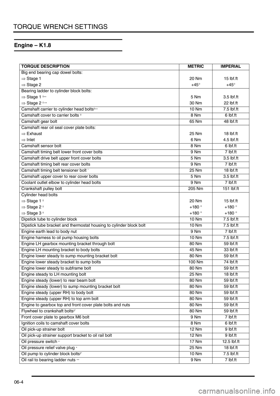
06-4
Engine – K1.8
TORQUE DESCRIPTION METRIC IMPERIAL
Big end bearing cap dowel bolts:
⇒ Stage 120 Nm 15 lbf.ft
⇒ Stage 2+45°+45°
Bearing ladder to cylinder block bolts:
⇒ Stage 1
†++5 Nm 3.5 lbf.ft
⇒ Stage 2
† ++30 Nm 22 lbf.ft
Camshaft carrier to cylinder head bolts
†++10 Nm 7.5 lbf.ft
Camshaft cover to carrier bolts
†8 Nm 6 lbf.ft
Camshaft gear bolt 65 Nm 48 lbf.ft
Camshaft rear oil seal cover plate bolts:
⇒ Exhaust25 Nm 18 lbf.ft
⇒ Inlet6 Nm 4.5 lbf.ft
Camshaft sensor bolt 8 Nm 6 lbf.ft
Camshaft timing belt lower front cover bolts 9 Nm 7 lbf.ft
Camshaft drive belt upper front cover bolts 5 Nm 3.5 lbf.ft
Camshaft timing belt rear cover bolts 9 Nm 7 lbf.ft
Camshaft timing belt tensioner bolt
* 25 Nm 18 lbf.ft
Camshaft upper cover to rear cover bolts 5 Nm 3.5 lbf.ft
Coolant outlet elbow to cylinder head bolts 9 Nm 7 lbf.ft
Crankshaft pulley bolt 205 Nm 151 lbf.ft
Cylinder head bolts
⇒ Stage 1
†20 Nm 15 lbf.ft
⇒ Stage 2
†+180 °+180 °
⇒ Stage 3
†+180 °+180 °
Dipstick tube to cylinder block 10 Nm 7.5 lbf.ft
Dipstick tube bracket and thermostat housing to cylinder block bolt 10 Nm 7.5 lbf.ft
Engine earth lead to body nut 9 Nm 7 lbf.ft
Engine harness to oil pump housing bolts 10 Nm 7.5 lbf.ft
Engine LH gearbox mounting bracket through bolt 80 Nm 59 lbf.ft
Engine LH mounting bracket to body bolts 45 Nm 33 lbf.ft
Engine lower steady to sump mounting bracket bolt 80 Nm 59 lbf.ft
Engine lower steady bracket to sump bolts 100 Nm 74 lbf.ft
Engine lower steady to subframe bolt 80 Nm 59 lbf.ft
Engine steady to LH mounting bolt 25 Nm 18 lbf.ft
Engine steady (lower) to rear beam bolt 80 Nm 59 lbf.ft
Engine steady (lower) to sump mounting bracket bolt 80 Nm 59 lbf.ft
Engine steady (upper RH) to body bolt 80 Nm 59 lbf.ft
Engine steady (upper RH) to top arm bolt 80 Nm 59 lbf.ft
Engine to gearbox top and front cover plate bolts and nuts 80 Nm 59 lbf.ft
Flywheel to crankshaft bolts
†*80 Nm 59 lbf.ft
Front cover plate to gearbox M6 bolt 9 Nm 7 lbf.ft
Ignition coils to camshaft cover bolts 8 Nm 6 lbf.ft
Oil pick-up strainer bolt 12 Nm 9 lbf.ft
Oil pick-up strainer support bracket to oil rail bolt 12 Nm 9 lbf.ft
Oil pressure switch
+17 Nm 12.5 lbf.ft
Oil pressure relief valve plug
+25 Nm 18 lbf.ft
Oil pump to cylinder block bolts
†*10 Nm 7.5 lbf.ft
Oil rail to bearing ladder nuts
++9 Nm 7 lbf.ft
Page 129 of 1007
TORQUE WRENCH SETTINGS
06-26
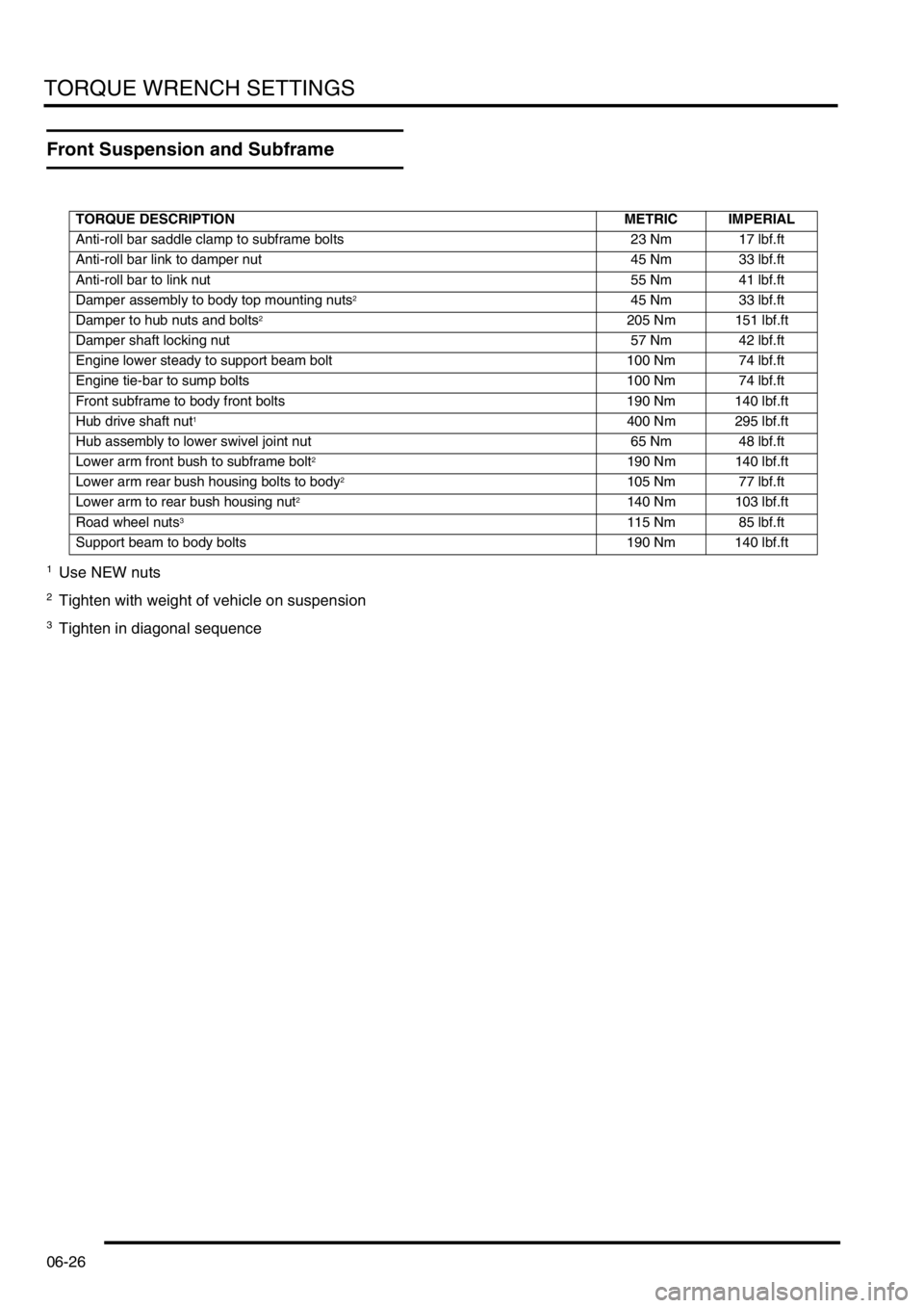
Front Suspension and Subframe
1 Use NEW nuts
2 Tighten with weight of vehicle on suspension
3 Tighten in diagonal sequence
TORQUE DESCRIPTION METRIC IMPERIAL
Anti-roll bar saddle clamp to subframe bolts 23 Nm 17 lbf.ft
Anti-roll bar link to damper nut 45 Nm 33 lbf.ft
Anti-roll bar to link nut 55 Nm 41 lbf.ft
Damper assembly to body top mounting nuts
245 Nm 33 lbf.ft
Damper to hub nuts and bolts
2205 Nm 151 lbf.ft
Damper shaft locking nut 57 Nm 42 lbf.ft
Engine lower steady to support beam bolt 100 Nm 74 lbf.ft
Engine tie-bar to sump bolts 100 Nm 74 lbf.ft
Front subframe to body front bolts 190 Nm 140 lbf.ft
Hub drive shaft nut
1400 Nm 295 lbf.ft
Hub assembly to lower swivel joint nut 65 Nm 48 lbf.ft
Lower arm front bush to subframe bolt
2190 Nm 140 lbf.ft
Lower arm rear bush housing bolts to body
2105 Nm 77 lbf.ft
Lower arm to rear bush housing nut
2140 Nm 103 lbf.ft
Road wheel nuts
3115 Nm 85 lbf.ft
Support beam to body bolts 190 Nm 140 lbf.ft
Page 206 of 1007
ENGINE - K SERIES KV6
REPAIRS 12-3-29
33.With an assistant depressing the brake pedal,
remove and discard LH and RH drive shaft
nuts.
34.Remove rear beam.
+ FRONT SUSPENSION, REPAIRS,
Rear beam.
35.Remove exhaust front pipe.
+ MANIFOLDS & EXHAUST SYSTEMS
- K SERIES KV6, REPAIRS, Front pipe - Non
NAS.
+ MANIFOLDS & EXHAUST SYSTEMS
- K SERIES KV6, REPAIRS, Front pipe - NAS.
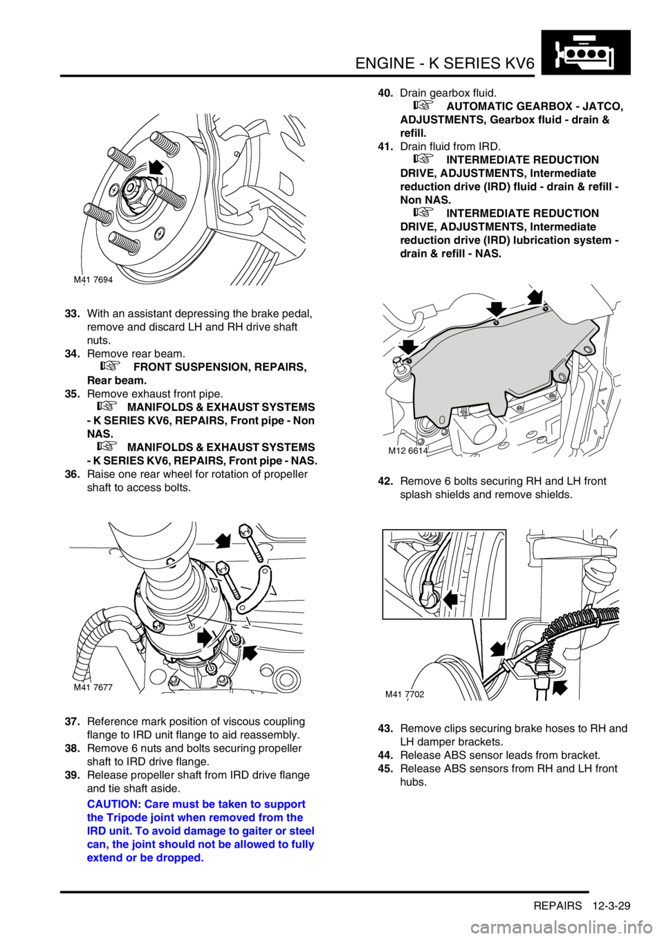
36.Raise one rear wheel for rotation of propeller
shaft to access bolts.
37.Reference mark position of viscous coupling
flange to IRD unit flange to aid reassembly.
38.Remove 6 nuts and bolts securing propeller
shaft to IRD drive flange.
39.Release propeller shaft from IRD drive flange
and tie shaft aside.
CAUTION: Care must be taken to support
the Tripode joint when removed from the
IRD unit. To avoid damage to gaiter or steel
can, the joint should not be allowed to fully
extend or be dropped.40.Drain gearbox fluid.
+ AUTOMATIC GEARBOX - JATCO,
ADJUSTMENTS, Gearbox fluid - drain &
refill.
41.Drain fluid from IRD.
+ INTERMEDIATE REDUCTION
DRIVE, ADJUSTMENTS, Intermediate
reduction drive (IRD) fluid - drain & refill -
Non NAS.
+ INTERMEDIATE REDUCTION
DRIVE, ADJUSTMENTS, Intermediate
reduction drive (IRD) lubrication system -
drain & refill - NAS.
42.Remove 6 bolts securing RH and LH front
splash shields and remove shields.
43.Remove clips securing brake hoses to RH and
LH damper brackets.
44.Release ABS sensor leads from bracket.
45.Release ABS sensors from RH and LH front
hubs.
M12 6614
Page 210 of 1007
ENGINE - K SERIES KV6
REPAIRS 12-3-33
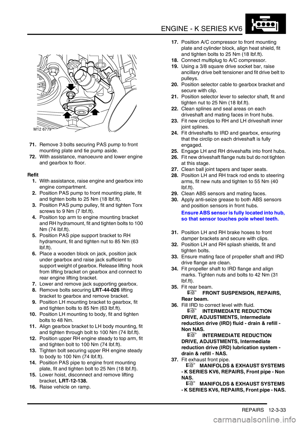
71.Remove 3 bolts securing PAS pump to front
mounting plate and tie pump aside.
72.With assistance, manoeuvre and lower engine
and gearbox to floor.
Refit
1.With assistance, raise engine and gearbox into
engine compartment.
2.Position PAS pump to front mounting plate, fit
and tighten bolts to 25 Nm (18 lbf.ft).
3.Position PAS pump pulley, fit and tighten Torx
screws to 9 Nm (7 lbf.ft).
4.Position top arm to engine mounting bracket
and RH hydramount, fit and tighten bolts to 100
Nm (74 lbf.ft).
5.Position PAS pipe support bracket to RH
hydramount, fit and tighten nut to 85 Nm (63
lbf.ft).
6.Place a wooden block on jack, position jack
under gearbox and raise jack sufficient to
support weight of gearbox. Release lifting hook
from lifting bracket on gearbox and connect to
rear engine lifting bracket.
7.Lower and remove jack supporting gearbox.
8.Remove bolts securing LRT-44-026 lifting
bracket to gearbox and remove bracket.
9.Position LH mounting bracket to gearbox, fit
and tighten bolts to 85 Nm (63 lbf.ft).
10.Position LH mounting to body, fit and tighten
bolts to 48 Nm.
11.Align gearbox bracket to LH body mounting, fit
and tighten through bolt to 100 Nm (74 lbf.ft).
12.Position upper RH engine steady to top arm, fit
and tighten bolt to 100 Nm (74 lbf.ft).
13.Tighten bolt securing upper RH engine steady
to body to 100 Nm (74 lbf.ft).
14.Position PAS pipe to engine front mounting
plate, fit and tighten bolt to 25 Nm (18 lbf.ft).
15.Lower hoist, disconnect and remove lifting
bracket, LRT-12-138.
16.Raise vehicle on ramp.17.Position A/C compressor to front mounting
plate and cylinder block, align heat shield, fit
and tighten bolts to 25 Nm (18 lbf.ft).
18.Connect multiplug to A/C compressor.
19.Using a 3/8 square drive socket bar, raise
ancillary drive belt tensioner and fit drive belt to
pulleys.
20.Position selector cable to gearbox bracket and
secure with clip.
21.Position selector lever to selector shaft, fit and
tighten nut to 25 Nm (18 lbf.ft).
22.Clean splines and seal areas on each
driveshaft and mating faces in front hubs.
23.Fit new circlips to RH and LH driveshaft inner
joint splines.
24.Fit driveshafts to IRD and gearbox, ensuring
that the circlip on each driveshaft is fully
engaged.
25.Engage LH and RH driveshafts into front hubs.
26.Fit new driveshaft flange nuts but do not tighten
at this stage.
27.Clean ball joint tapers and taper seats.
28.Position LH and RH track rod ends to steering
arms, fit new nuts and tighten to 55 Nm (40
lbf.ft).
29.Clean ABS sensors and mating faces.
30.Apply anti-seize grease to both ABS sensors
and position sensors in front hubs.
Ensure ABS sensor is fully located into hub,
so that sensor touches pole wheel teeth.
31.Position LH and RH brake hoses to front
damper brackets and secure with clips.
32.Position LH and RH splash shields, fit and
tighten bolts.
33.Ensure mating face of propeller shaft and IRD
drive flange are clean.
34.Fit propeller shaft to IRD flange and align
marks. Tighten nuts and bolts to 42 Nm (31
lbf.ft).
35.Fit rear beam.
+ FRONT SUSPENSION, REPAIRS,
Rear beam.
36.Fill IRD to correct level with fluid.
+ INTERMEDIATE REDUCTION
DRIVE, ADJUSTMENTS, Intermediate
reduction drive (IRD) fluid - drain & refill -
Non NAS.
+ INTERMEDIATE REDUCTION
DRIVE, ADJUSTMENTS, Intermediate
reduction drive (IRD) lubrication system -
drain & refill - NAS.
37.Fit exhaust front pipe.
+ MANIFOLDS & EXHAUST SYSTEMS
- K SERIES KV6, REPAIRS, Front pipe - Non
NAS.
+ MANIFOLDS & EXHAUST SYSTEMS
- K SERIES KV6, REPAIRS, Front pipe - NAS.
Page 216 of 1007
ENGINE - K SERIES KV6
REPAIRS 12-3-39
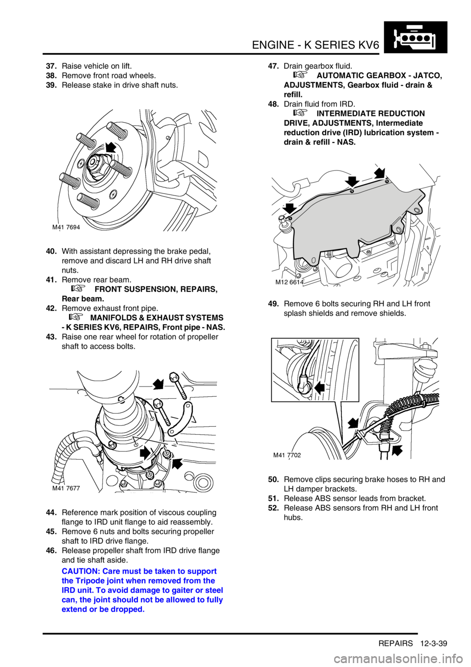
37.Raise vehicle on lift.
38.Remove front road wheels.
39.Release stake in drive shaft nuts.
40.With assistant depressing the brake pedal,
remove and discard LH and RH drive shaft
nuts.
41.Remove rear beam.
+ FRONT SUSPENSION, REPAIRS,
Rear beam.
42.Remove exhaust front pipe.
+ MANIFOLDS & EXHAUST SYSTEMS
- K SERIES KV6, REPAIRS, Front pipe - NAS.
43.Raise one rear wheel for rotation of propeller
shaft to access bolts.
44.Reference mark position of viscous coupling
flange to IRD unit flange to aid reassembly.
45.Remove 6 nuts and bolts securing propeller
shaft to IRD drive flange.
46.Release propeller shaft from IRD drive flange
and tie shaft aside.
CAUTION: Care must be taken to support
the Tripode joint when removed from the
IRD unit. To avoid damage to gaiter or steel
can, the joint should not be allowed to fully
extend or be dropped.47.Drain gearbox fluid.
+ AUTOMATIC GEARBOX - JATCO,
ADJUSTMENTS, Gearbox fluid - drain &
refill.
48.Drain fluid from IRD.
+ INTERMEDIATE REDUCTION
DRIVE, ADJUSTMENTS, Intermediate
reduction drive (IRD) lubrication system -
drain & refill - NAS.
49.Remove 6 bolts securing RH and LH front
splash shields and remove shields.
50.Remove clips securing brake hoses to RH and
LH damper brackets.
51.Release ABS sensor leads from bracket.
52.Release ABS sensors from RH and LH front
hubs.
M12 6614
Page 221 of 1007

ENGINE - K SERIES KV6
12-3-44 REPAIRS
35.Fit rear beam.
+ FRONT SUSPENSION, REPAIRS,
Rear beam.
36.Fill IRD to correct level with fluid.
+ INTERMEDIATE REDUCTION
DRIVE, ADJUSTMENTS, Intermediate
reduction drive (IRD) lubrication system -
drain & refill - NAS.
37.Fit exhaust front pipe.
+ MANIFOLDS & EXHAUST SYSTEMS
- K SERIES KV6, REPAIRS, Front pipe - NAS.
38.With assistant depressing the brake pedal,
tighten front hub nuts to 400 Nm.
39.Stake nuts to drive shafts
40.Fit front road wheels, fit and tighten nuts to 115
Nm.
41.Lower vehicle on lift.
42.Connect brake servo vacuum hose to inlet
manifold chamber.
43.Connect coolant hose to underside of
expansion tank and secure with clip.
44.Connect expansion tank hose to inlet manifold
and secure clip.
45.Connect top hose to radiator and secure with
clip. Position hose in bracket.
46.Connect heater feed and return hoses and
secure with clips.
47.Connect throttle inner cable to throttle cam and
secure outer cable in abutment bracket.
48.Connect hose to purge valve.
49.Fit purge hose into clip.
50.Connect fuel hose to fuel rail pipe, fit rubber
sleeve over hose connector.
51.Connect gearbox harness multiplugs and
secure multiplugs in mounting bracket clips.
52.Connect Lucar connector to starter solenoid.
53.Position earth lead to gearbox housing, fit and
tighten bolt to 25 Nm.
54.Position engine harness to 'E' box mounting
bracket and secure with clips.
55.Connect earth header multiplug.
56.Connect multiplug to under bonnet fuse box.
57.Position battery and starter motor lead to under
bonnet fuse box, fit and tighten bolts to 8 Nm.
58.Fit under bonnet fuse box cover.
59.Position 'E' box, secure in retaining clip, fit and
tighten nut to 9 Nm.
60.Fit carrier to 'E' box.
61.Fit air ducting to 'E' box.
62.Fit body harness to 'E' box, secure grommet
and harness clip.
63.Connect 'E' box cooling fan multiplug.
64.Connect multiplug to 'E' box temperature
sensor.
65.Connect multiplug to gearbox ECU.
66.Position engine harness to 'E' box and secure
grommet.67.Fit engine harness clamp and secure with
screws.
68.Connect engine harness multiplug to body
harness multiplug and fit multiplug to 'E' box.
69.Fit heated front screen harness to battery
positive cable and tighten bolt to 15 Nm (11
lbf.ft).
70.Fit engine ECM.
+ ENGINE MANAGEMENT SYSTEM -
SIEMENS, REPAIRS, Engine control module
(ECM) - fuel - NAS.
71.Fit battery carrier.
+ CHARGING AND STARTING,
REPAIRS, Carrier - battery.
72.Fill cooling system.
+ COOLING SYSTEM - K SERIES KV6,
ADJUSTMENTS, Coolant - drain and refill.
73.Connect the battery earth lead.
74.Fill gearbox with fluid.
+ AUTOMATIC GEARBOX - JATCO,
ADJUSTMENTS, Gearbox fluid - drain &
refill.
75.Fit the engine acoustic cover.
+ ENGINE - K SERIES KV6, REPAIRS,
Cover - engine acoustic.
76.Untie and close bonnet.
Page 409 of 1007

INTERMEDIATE REDUCTION DRIVE
41-6 REPAIRS
Refit
1.Clean mating faces of IRD and gearbox.
2.Lubricate and fit new 'O' ring
3.With assistance, fit IRD.
4.Fit bolts securing IRD to gearbox and tighten
sufficiently only to pull mating faces of IRD and
gearbox together at this stage.
5.Fit IRD support brackets, tighten sufficiently to
pull mating faces together.
6.Final tighten bolts securing IRD to gearbox to
90 Nm (66 lbf.ft).
7.Final tighten bolts securing IRD support
brackets in the following sequence:
lM8 bolts securing support brackets to IRD
37 Nm (22 lbf.ft)
lM10 bolts securing support brackets to IRD
50 Nm (22 lbf.ft)
l3 bolts securing support bracket to cylinder
block 25 Nm (18 lbf.ft)
l3 bolts securing support bracket to sump at
45 Nm (33 lbf.ft).
8.Position lower engine steady, 'TOP' mark
uppermost. Fit bolt but do not tighten at this
stage.
9.Connect coolant hoses and secure with clips.
10.Connect breather hose to IRD housing.
11.Clean propeller shaft flange and mating face.
12.Fit propeller shaft to IRD flange and align
marks. Tighten nuts and bolts to 40 Nm (30
lbf.ft).
13.Inspect drive shaft oil seal, renew if worn or
damaged.14.Clean drive shaft and flange splines.
15.Fit new circlip to drive shaft.
16.With assistance, pull hub outwards, align drive
shaft and fit to IRD taking care not to damage
oil seal.
17.Fit splash shield and secure with bolts.
18.Fit exhaust front pipe.
+ MANIFOLDS & EXHAUST SYSTEMS
- Td4, REPAIRS, Exhaust pipe - front.
19.Fit rear beam.
+ FRONT SUSPENSION, REPAIRS,
Rear beam.
20.Final tighten bolt securing lower engine steady
to IRD support bracket to 100 Nm (74 lbf.ft).
21.Remove stand(s) and lower vehicle.
22.Fill IRD to correct level with fluid.
+ INTERMEDIATE REDUCTION
DRIVE, ADJUSTMENTS, Intermediate
reduction drive (IRD) fluid - drain & refill -
Non NAS.
23.Fill gearbox with fluid.
+ MANUAL GEARBOX - GETRAG,
ADJUSTMENTS, Gearbox oil - drain and
refill.
+ AUTOMATIC GEARBOX - JATCO,
ADJUSTMENTS, Gearbox fluid - drain &
refill.
24.Connect battery earth lead.
25.Refill cooling system.
+ COOLING SYSTEM - Td4,
ADJUSTMENTS, Coolant - drain and refill.
Page 412 of 1007
INTERMEDIATE REDUCTION DRIVE
REPAIRS 41-9
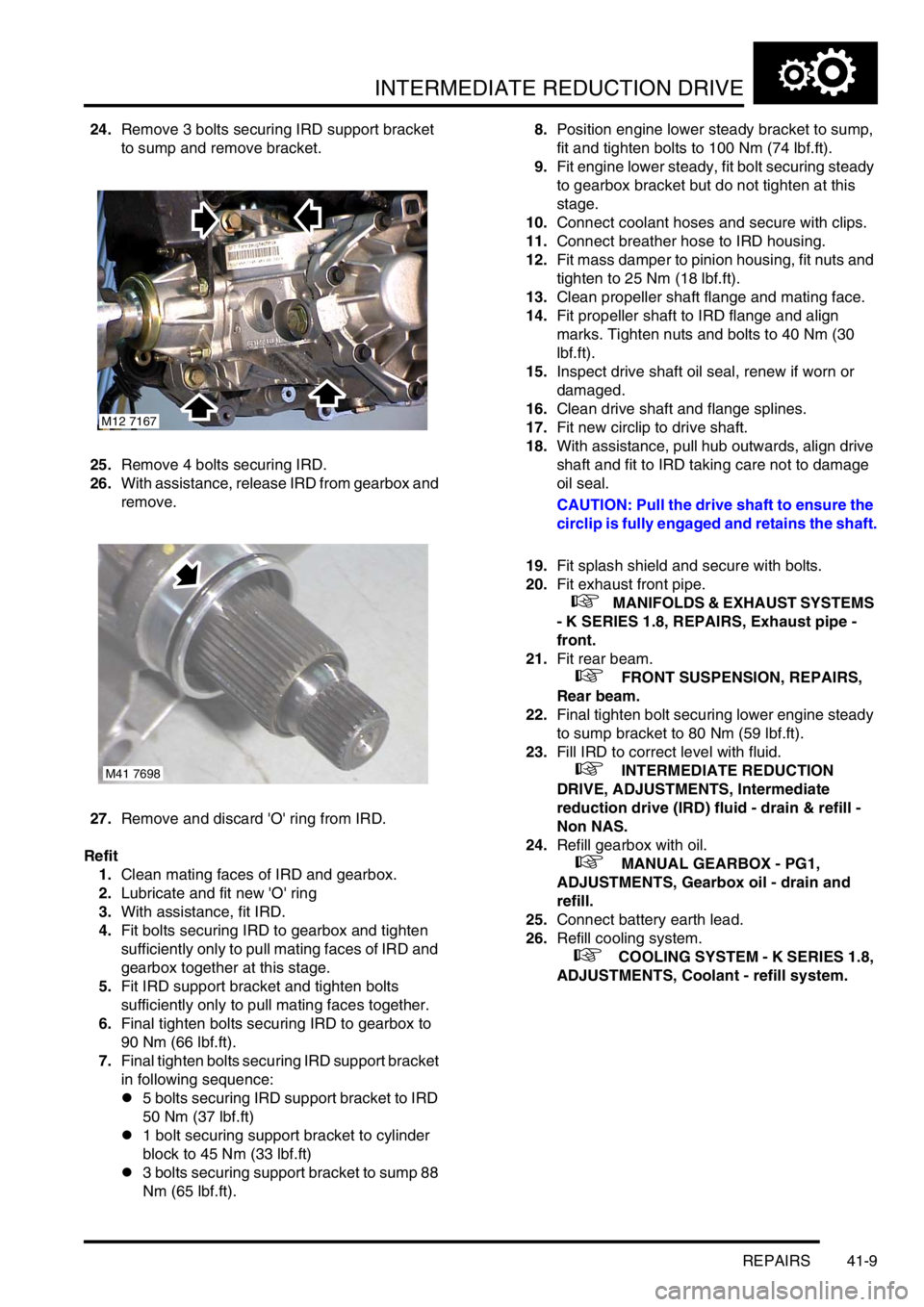
24.Remove 3 bolts securing IRD support bracket
to sump and remove bracket.
25.Remove 4 bolts securing IRD.
26.With assistance, release IRD from gearbox and
remove.
27.Remove and discard 'O' ring from IRD.
Refit
1.Clean mating faces of IRD and gearbox.
2.Lubricate and fit new 'O' ring
3.With assistance, fit IRD.
4.Fit bolts securing IRD to gearbox and tighten
sufficiently only to pull mating faces of IRD and
gearbox together at this stage.
5.Fit IRD support bracket and tighten bolts
sufficiently only to pull mating faces together.
6.Final tighten bolts securing IRD to gearbox to
90 Nm (66 lbf.ft).
7.Final tighten bolts securing IRD support bracket
in following sequence:
l5 bolts securing IRD support bracket to IRD
50 Nm (37 lbf.ft)
l1 bolt securing support bracket to cylinder
block to 45 Nm (33 lbf.ft)
l3 bolts securing support bracket to sump 88
Nm (65 lbf.ft).8.Position engine lower steady bracket to sump,
fit and tighten bolts to 100 Nm (74 lbf.ft).
9.Fit engine lower steady, fit bolt securing steady
to gearbox bracket but do not tighten at this
stage.
10.Connect coolant hoses and secure with clips.
11.Connect breather hose to IRD housing.
12.Fit mass damper to pinion housing, fit nuts and
tighten to 25 Nm (18 lbf.ft).
13.Clean propeller shaft flange and mating face.
14.Fit propeller shaft to IRD flange and align
marks. Tighten nuts and bolts to 40 Nm (30
lbf.ft).
15.Inspect drive shaft oil seal, renew if worn or
damaged.
16.Clean drive shaft and flange splines.
17.Fit new circlip to drive shaft.
18.With assistance, pull hub outwards, align drive
shaft and fit to IRD taking care not to damage
oil seal.
CAUTION: Pull the drive shaft to ensure the
circlip is fully engaged and retains the shaft.
19.Fit splash shield and secure with bolts.
20.Fit exhaust front pipe.
+ MANIFOLDS & EXHAUST SYSTEMS
- K SERIES 1.8, REPAIRS, Exhaust pipe -
front.
21.Fit rear beam.
+ FRONT SUSPENSION, REPAIRS,
Rear beam.
22.Final tighten bolt securing lower engine steady
to sump bracket to 80 Nm (59 lbf.ft).
23.Fill IRD to correct level with fluid.
+ INTERMEDIATE REDUCTION
DRIVE, ADJUSTMENTS, Intermediate
reduction drive (IRD) fluid - drain & refill -
Non NAS.
24.Refill gearbox with oil.
+ MANUAL GEARBOX - PG1,
ADJUSTMENTS, Gearbox oil - drain and
refill.
25.Connect battery earth lead.
26.Refill cooling system.
+ COOLING SYSTEM - K SERIES 1.8,
ADJUSTMENTS, Coolant - refill system.
M12 7167
M41 7698