airbag LAND ROVER FREELANDER 2001 Workshop Manual
[x] Cancel search | Manufacturer: LAND ROVER, Model Year: 2001, Model line: FREELANDER, Model: LAND ROVER FREELANDER 2001Pages: 1007, PDF Size: 23.47 MB
Page 15 of 1007

CONTENTS
12 CONTENTS
RESTRAINT SYSTEMS ............................................................................ 75-1
REPAIRS
Automatic belt assembly - front - 3 door ......................................................................................... 75-1
Automatic belt assembly - front - 5 door ......................................................................................... 75-2
Seat belt - centre - rear ................................................................................................................... 75-3
Seat belt - rear - LH ........................................................................................................................ 75-4
Adjustable mounting - seat belt - 'B' pillar ....................................................................................... 75-5
Stalk - rear seat belt - LH - 3 door .................................................................................................. 75-6
Stalk - rear seat belt - LH - 5 door .................................................................................................. 75-7
Pre-tensioner - seat belt - front ....................................................................................................... 75-8
Pre-tensioner - seat belt - front - deployment - off vehicle ............................................................. 75-9
Stalk - rear seat belt - centre .......................................................................................................... 75-11
Air bag - steering wheel .................................................................................................................. 75-13
Air bag - fascia - passenger - up to 04MY ...................................................................................... 75-14
Air bag - fascia - passenger - from 04MY ....................................................................................... 75-15
Diagnostic control unit (DCU) ........................................................................................................ 75-16
Airbag - passenger - deployment - off vehicle ............................................................................... 75-17
Rotary coupler - (SRS) air bag system ........................................................................................... 75-19
Airbag module - steering wheel - deployment - off vehicle ............................................................ 75-20
Airbag module - steering wheel - deployment - in-vehicle .............................................................. 75-21
Pre-tensioner - front seatbelt - deployment - in-vehicle .................................................................. 75-23
DOORS...................................................................................................... 76-1-1
ADJUSTMENTS
Door - front or rear - adjust on striker ............................................................................................ 76-1-1
Door - front - align on hinges .......................................................................................................... 76-1-2
REPAIRS
Door assembly - front - remove for access & refit .......................................................................... 76-1-3
Door assembly - rear - remove for access & refit ........................................................................... 76-1-4
Door - tail assembly - remove for access & refit ............................................................................. 76-1-5
Glass - front door .......................................................................................................................... 76-1-6
Glass - rear door ............................................................................................................................ 76-1-7
Rubber/felt - glass channel - front door ........................................................................................ 76-1-8
Rubber/felt - glass channel - rear door .......................................................................................... 76-1-9
Glass - tail door .............................................................................................................................. 76-1-10
Quarter light - rear door .................................................................................................................. 76-1-11
Glass regulator - tail door .............................................................................................................. 76-1-12
Seal - waist inner - tail door ............................................................................................................ 76-1-13
Trim casing - front door - 3 door .................................................................................................... 76-1-14
Trim casing - front door - 5 door - up to 04MY................................................................................ 76-1-15
Trim casing - front door - 5 door - from 04MY ................................................................................ 76-1-16
Trim casing - rear door - up to 04MY .............................................................................................. 76-1-18
Trim casing - rear door - from 04MY............................................................................................... 76-1-20
Trim casing - tail door ..................................................................................................................... 76-1-22
Plastic sheet - front door - lower - 3 door........................................................................................ 76-1-23
Pocket - front door - 3 door ............................................................................................................. 76-1-23
Plastic sheet - front door - upper - 3 door ....................................................................................... 76-1-24
Plastic sheet - tail door ................................................................................................................... 76-1-24
Plastic sheet - front door - 5 door .................................................................................................. 76-1-25
Plastic sheet - rear door.................................................................................................................. 76-1-25
Latch - front door - 3 door ............................................................................................................... 76-1-26
Latch - front door - 5 door .............................................................................................................. 76-1-27
Latch - rear door ............................................................................................................................. 76-1-28
Latch - tail door ............................................................................................................................... 76-1-29
Page 37 of 1007

GENERAL INFORMATION
03-6
Waste Management
One of the major ways that pollution can be reduced
is by the careful handling, storage and disposal of all
waste materials that occur on sites. Legislation
makes it illegal to dispose of waste materials other
than to licensed waste carriers and disposal sites.
This means that it is necessary to not only know what
the waste materials are, but also to have the
necessary documentation and licenses.
Handling and storage of waste
Ensure that waste materials are not poured down the
drain or onto soils. They should be stored in such a
way as to prevent the escape of material to land,
water or air.
They must also be segregated into different types of
waste e.g. oil, metals, batteries, used vehicle
components. This will prevent any reaction between
different materials and assist in disposal.
Disposal of waste
Disposal of waste materials must only be to waste
carriers who are licensed to carry those particular
waste materials and all the necessary
documentation must be completed. The waste
carrier is responsible for ensuring that the waste is
taken to the correct disposal sites.Dispose of waste in accordance with the following
guidelines:
lFuel, hydraulic fluid, anti-freeze and oil –
keep separate and dispose of to specialist
contractor.
lRefrigerant – collect using specialist
equipment and containers, and reuse.
lDetergents – safe to pour down the foul drain
if diluted.
lPaint, thinners – keep separate and dispose of
to specialist contractor.
lComponents – send back to supplier for
refurbishment, or disassemble and reuse any
suitable parts. Dispose of the remainder in
ordinary waste.
lSmall parts – reuse any suitable parts, dispose
of the remainder in ordinary waste.
lMetals – can be sold if kept separate from
general waste.
lTyres – keep separate and dispose of to
specialist contractor.
lPackaging – compact as much as possible and
dispose of in ordinary waste.
lAsbestos-containing – keep separate and
dispose of to specialist contractor.
lOily and fuel wastes (e.g. rags, used spill kit
material) – keep separate and dispose of to
specialist contractor.
lAir filters – keep separate and dispose of to
specialist contractor.
lRubber/plastics – dispose of in ordinary
waste.
lHoses – dispose of in ordinary waste.
lBatteries – keep separate and dispose of to
specialist contractor.
lAirbags (explosives) – keep separate and
dispose of to specialist contractor.
lElectrical components – send back to
supplier for refurbishment, or disassemble and
reuse any suitable parts. Dispose of the
remainder in ordinary waste.
lElectronic components – send back to
supplier for refurbishment, or disassemble and
reuse any suitable parts. Dispose of the
remainder in ordinary waste.
lCatalysts – can be sold if kept separate from
general waste.
lUsed spill-absorbing material – keep
separate and dispose of to specialist contractor.
lOffice waste – recycle paper and toner/ink
cartridges, dispose of the remainder in ordinary
waste.
Page 51 of 1007
GENERAL INFORMATION
03-20
Disciplines
Switch off the ignition prior to making any connection
or disconnection in the system, to prevent electrical
surges caused by disconnecting 'live' connections
damaging electronic components.
Ensure hands and work surfaces are clean and free
of grease, swarf, etc. Grease collects dirt which can
cause electrical tracking (short-circuits) or high-
resistance contacts.
When handling printed circuit boards, treat with care
and hold by the edges only; note that some electronic
components are susceptible to body static.
Connectors should never be subjected to forced
removal or refit, especially inter-board connectors.
Damaged contacts can cause short-circuit and
open-circuit fault conditions.
Prior to commencing test, and periodically during a
test, touch a good vehicle body earth to discharge
static charge. Some electronic components are
vulnerable to the static electricity that may be
generated by the operator.
Grease for electrical connectors
Some under bonnet and under body connectors may
be protected against corrosion by the application of a
special grease during vehicle production. Should
connectors be disturbed in service, or repaired or
replaced, additional grease should be re-applied:
Part No. BAU 5811, available in 150 gm tubs.
NOTE: The use of greases other than BAU 5811
must be avoided as they can migrate into relays,
switches etc. contaminating the contacts and leading
to intermittent operation or failure.
Supplementary restraint system
precautions
General
The Supplementary Restraint System (SRS)
provides active protection for vehicle occupants in
the event of a serious collision. The system
components include airbags and pre-tensioner seat
belts which are automatically deployed when a
severe frontal crash condition is detected.
The SRS pyrotechnic components could be
potentially hazardous to the service engineer if not
handled correctly. The following guidelines are
intended to alert the service engineer to potential
sources of danger and emphasise the importance of
ensuring the integrity of SRS components fitted to
the vehicle.
In order to assure system integrity, it is essential that
the SRS system is regularly checked and maintained
so that it is ready for operation in the event of an
accident.
Where necessary, additional specific precautions are
detailed in the relevant sections of this Manual which
should be referred to prior to commencing repair
operations.
WARNING: Always follow the 'SRS Precautions'
and the correct procedures for working on SRS
components. Persons working on SRS systems
must be fully trained and have been issued with
copies of the Safety guidelines.
WARNING: It is imperative that before any work
is undertaken on the SRS system the appropriate
information is read thoroughly.
WARNING: The airbag module contains sodium
azide which is poisonous and extremely
flammable. Contact with water, acid or heavy
metals may produce harmful or explosive
compounds. Do not dismantle, incinerate or
bring into contact with electricity, before the unit
has been deployed.
WARNING: Always replace a seat belt assembly
that has withstood the strain of a severe vehicle
impact, or if the webbing shows signs of fraying.
WARNING: Always disconnect the vehicle
battery before carrying out any electric welding
on a vehicle fitted with an SRS system.
CAUTION: Do not expose an airbag module or
seat belt pre-tensioner to heat exceeding 85º C
(185º F).
Page 52 of 1007
GENERAL INFORMATION
03-21
It should be noted that these precautions are not
restricted to operations performed when servicing
the SRS system, the same care should be exercised
when working on ancillary systems and components
located in the vicinity of SRS components; these
include but are not limited to:
lSteering system – steering wheel airbag,
rotary coupler.
lFront fascia – passenger front airbag (where
fitted); SRS DCU behind centre console, on
transmission tunnel under the HeVAC system.
lFront seats – seat belt pre-tensioners, integral
with seat belt buckle assembly.
lElectrical system – SRS harnesses, link leads
and connectors.
Making the SRS system safe
Before working on or in the vicinity of SRS
components, ensure the system is rendered safe by
performing the following procedures:
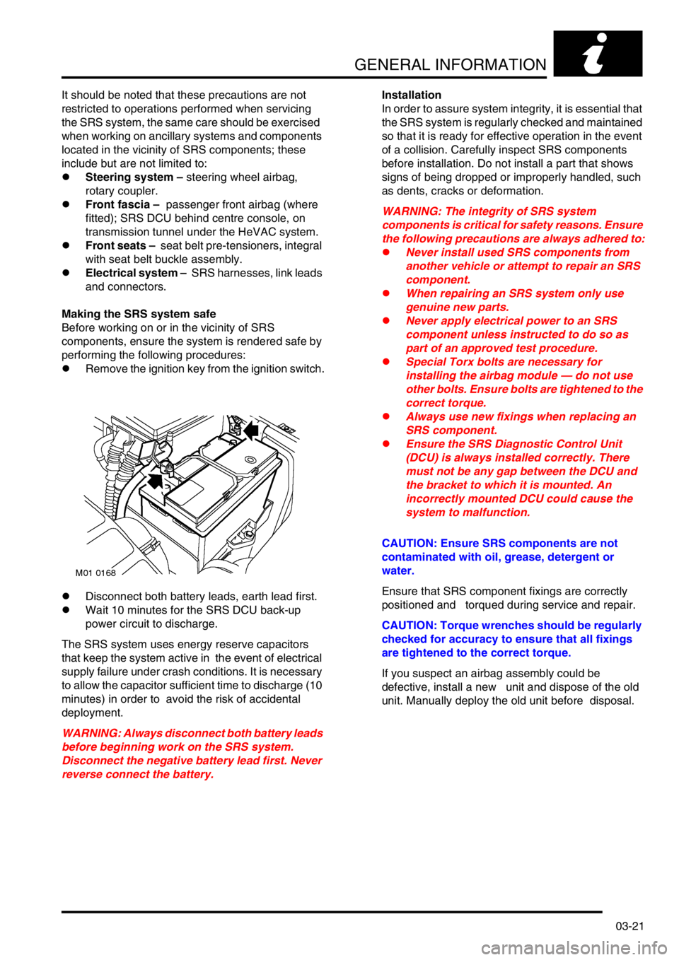
lRemove the ignition key from the ignition switch.
lDisconnect both battery leads, earth lead first.
lWait 10 minutes for the SRS DCU back-up
power circuit to discharge.
The SRS system uses energy reserve capacitors
that keep the system active in the event of electrical
supply failure under crash conditions. It is necessary
to allow the capacitor sufficient time to discharge (10
minutes) in order to avoid the risk of accidental
deployment.
WARNING: Always disconnect both battery leads
before beginning work on the SRS system.
Disconnect the negative battery lead first. Never
reverse connect the battery.Installation
In order to assure system integrity, it is essential that
the SRS system is regularly checked and maintained
so that it is ready for effective operation in the event
of a collision. Carefully inspect SRS components
before installation. Do not install a part that shows
signs of being dropped or improperly handled, such
as dents, cracks or deformation.
WARNING: The integrity of SRS system
components is critical for safety reasons. Ensure
the following precautions are always adhered to:
lNever install used SRS components from
another vehicle or attempt to repair an SRS
component.
lWhen repairing an SRS system only use
genuine new parts.
lNever apply electrical power to an SRS
component unless instructed to do so as
part of an approved test procedure.
lSpecial Torx bolts are necessary for
installing the airbag module — do not use
other bolts. Ensure bolts are tightened to the
correct torque.
lAlways use new fixings when replacing an
SRS component.
lEnsure the SRS Diagnostic Control Unit
(DCU) is always installed correctly. There
must not be any gap between the DCU and
the bracket to which it is mounted. An
incorrectly mounted DCU could cause the
system to malfunction.
CAUTION: Ensure SRS components are not
contaminated with oil, grease, detergent or
water.
Ensure that SRS component fixings are correctly
positioned and torqued during service and repair.
CAUTION: Torque wrenches should be regularly
checked for accuracy to ensure that all fixings
are tightened to the correct torque.
If you suspect an airbag assembly could be
defective, install a new unit and dispose of the old
unit. Manually deploy the old unit before disposal.
Page 53 of 1007
GENERAL INFORMATION
03-22
SRS component testing
The SRS components are triggered using relatively
low operating currents, always adhere to the
following precautions:
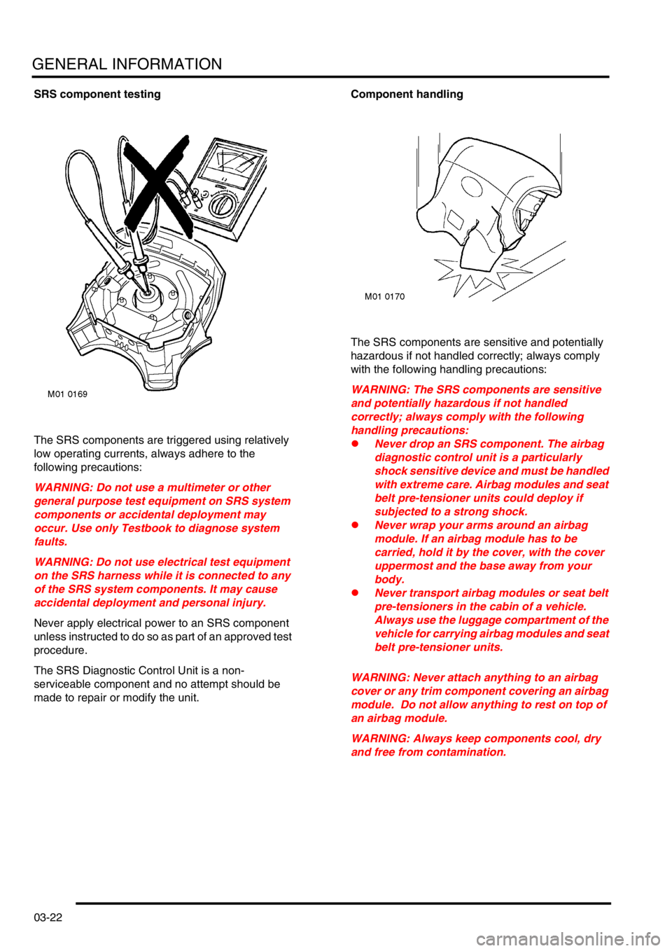
WARNING: Do not use a multimeter or other
general purpose test equipment on SRS system
components or accidental deployment may
occur. Use only Testbook to diagnose system
faults.
WARNING: Do not use electrical test equipment
on the SRS harness while it is connected to any
of the SRS system components. It may cause
accidental deployment and personal injury.
Never apply electrical power to an SRS component
unless instructed to do so as part of an approved test
procedure.
The SRS Diagnostic Control Unit is a non-
serviceable component and no attempt should be
made to repair or modify the unit.Component handling
The SRS components are sensitive and potentially
hazardous if not handled correctly; always comply
with the following handling precautions:
WARNING: The SRS components are sensitive
and potentially hazardous if not handled
correctly; always comply with the following
handling precautions:
lNever drop an SRS component. The airbag
diagnostic control unit is a particularly
shock sensitive device and must be handled
with extreme care. Airbag modules and seat
belt pre-tensioner units could deploy if
subjected to a strong shock.
lNever wrap your arms around an airbag
module. If an airbag module has to be
carried, hold it by the cover, with the cover
uppermost and the base away from your
body.
lNever transport airbag modules or seat belt
pre-tensioners in the cabin of a vehicle.
Always use the luggage compartment of the
vehicle for carrying airbag modules and seat
belt pre-tensioner units.
WARNING: Never attach anything to an airbag
cover or any trim component covering an airbag
module. Do not allow anything to rest on top of
an airbag module.
WARNING: Always keep components cool, dry
and free from contamination.
Page 54 of 1007
GENERAL INFORMATION
03-23
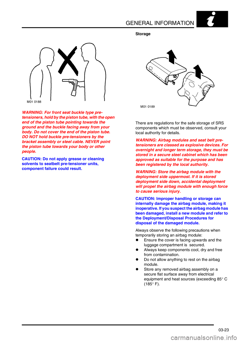
WARNING: For front seat buckle type pre-
tensioners, hold by the piston tube, with the open
end of the piston tube pointing towards the
ground and the buckle facing away from your
body. Do not cover the end of the piston tube.
DO NOT hold buckle pre-tensioners by the
bracket assembly or steel cable. NEVER point
the piston tube towards your body or other
people.
CAUTION: Do not apply grease or cleaning
solvents to seatbelt pre-tensioner units,
component failure could result.Storage
There are regulations for the safe storage of SRS
components which must be observed, consult your
local authority for details.
WARNING: Airbag modules and seat belt pre-
tensioners are classed as explosive devices. For
overnight and longer term storage, they must be
stored in a secure steel cabinet which has been
approved as suitable for the purpose and has
been registered by the local authority.
WARNING: Store the airbag module with the
deployment side uppermost. If it is stored
deployment side down, accidental deployment
will propel the airbag module with enough force
to cause serious injury.
CAUTION: Improper handling or storage can
internally damage the airbag module, making it
inoperative. If you suspect the airbag module has
been damaged, install a new module and refer to
the Deployment/Disposal Procedures for
disposal of the damaged module.
Always observe the following precautions when
temporarily storing an airbag module:
lEnsure the cover is facing upwards and the
luggage compartment is secured.
lAlways keep components cool, dry and free
from contamination.
lDo not allow anything to rest on the airbag
module.
lStore any removed airbag assembly on a
secure flat surface away from electrical
equipment and heat sources (exceeding 85° C
(185° F).
Page 55 of 1007
GENERAL INFORMATION
03-24
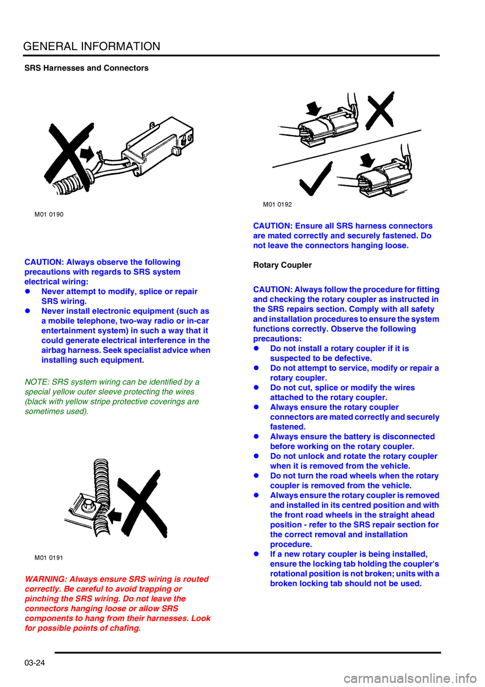
SRS Harnesses and Connectors
CAUTION: Always observe the following
precautions with regards to SRS system
electrical wiring:
lNever attempt to modify, splice or repair
SRS wiring.
lNever install electronic equipment (such as
a mobile telephone, two-way radio or in-car
entertainment system) in such a way that it
could generate electrical interference in the
airbag harness. Seek specialist advice when
installing such equipment.
NOTE: SRS system wiring can be identified by a
special yellow outer sleeve protecting the wires
(black with yellow stripe protective coverings are
sometimes used).
WARNING: Always ensure SRS wiring is routed
correctly. Be careful to avoid trapping or
pinching the SRS wiring. Do not leave the
connectors hanging loose or allow SRS
components to hang from their harnesses. Look
for possible points of chafing.CAUTION: Ensure all SRS harness connectors
are mated correctly and securely fastened. Do
not leave the connectors hanging loose.
Rotary Coupler
CAUTION: Always follow the procedure for fitting
and checking the rotary coupler as instructed in
the SRS repairs section. Comply with all safety
and installation procedures to ensure the system
functions correctly. Observe the following
precautions:
lDo not install a rotary coupler if it is
suspected to be defective.
lDo not attempt to service, modify or repair a
rotary coupler.
lDo not cut, splice or modify the wires
attached to the rotary coupler.
lAlways ensure the rotary coupler
connectors are mated correctly and securely
fastened.
lAlways ensure the battery is disconnected
before working on the rotary coupler.
lDo not unlock and rotate the rotary coupler
when it is removed from the vehicle.
lDo not turn the road wheels when the rotary
coupler is removed from the vehicle.
lAlways ensure the rotary coupler is removed
and installed in its centred position and with
the front road wheels in the straight ahead
position - refer to the SRS repair section for
the correct removal and installation
procedure.
lIf a new rotary coupler is being installed,
ensure the locking tab holding the coupler's
rotational position is not broken; units with a
broken locking tab should not be used.
Page 56 of 1007
GENERAL INFORMATION
03-25
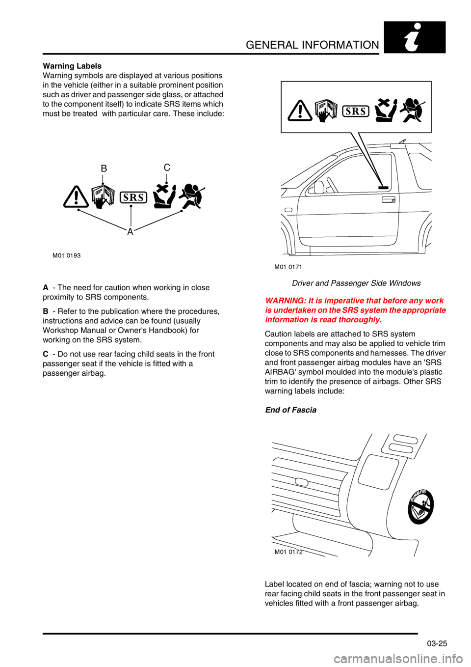
Warning Labels
Warning symbols are displayed at various positions
in the vehicle (either in a suitable prominent position
such as driver and passenger side glass, or attached
to the component itself) to indicate SRS items which
must be treated with particular care. These include:
A - The need for caution when working in close
proximity to SRS components.
B - Refer to the publication where the procedures,
instructions and advice can be found (usually
Workshop Manual or Owner's Handbook) for
working on the SRS system.
C - Do not use rear facing child seats in the front
passenger seat if the vehicle is fitted with a
passenger airbag.Driver and Passenger Side Windows
WARNING: It is imperative that before any work
is undertaken on the SRS system the appropriate
information is read thoroughly.
Caution labels are attached to SRS system
components and may also be applied to vehicle trim
close to SRS components and harnesses. The driver
and front passenger airbag modules have an 'SRS
AIRBAG' symbol moulded into the module's plastic
trim to identify the presence of airbags. Other SRS
warning labels include:
End of Fascia
Label located on end of fascia; warning not to use
rear facing child seats in the front passenger seat in
vehicles fitted with a front passenger airbag.
Page 57 of 1007
GENERAL INFORMATION
03-26
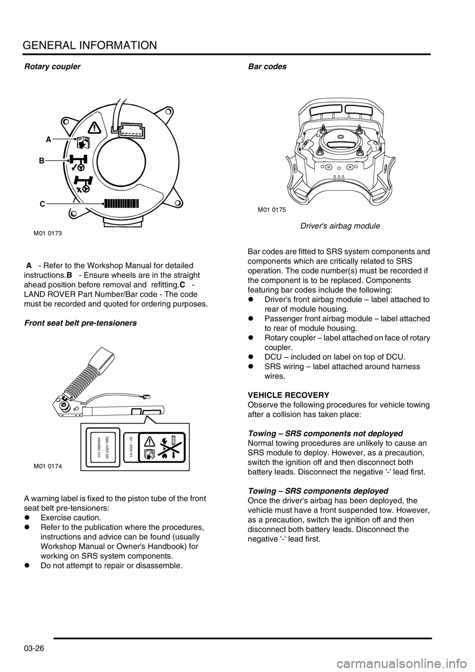
Rotary coupler
A - Refer to the Workshop Manual for detailed
instructions.B - Ensure wheels are in the straight
ahead position before removal and refitting.C -
LAND ROVER Part Number/Bar code - The code
must be recorded and quoted for ordering purposes.
Front seat belt pre-tensioners
A warning label is fixed to the piston tube of the front
seat belt pre-tensioners:
lExercise caution.
lRefer to the publication where the procedures,
instructions and advice can be found (usually
Workshop Manual or Owner's Handbook) for
working on SRS system components.
lDo not attempt to repair or disassemble.Bar codes
Driver's airbag module
Bar codes are fitted to SRS system components and
components which are critically related to SRS
operation. The code number(s) must be recorded if
the component is to be replaced. Components
featuring bar codes include the following:
lDriver's front airbag module – label attached to
rear of module housing.
lPassenger front airbag module – label attached
to rear of module housing.
lRotary coupler – label attached on face of rotary
coupler.
lDCU – included on label on top of DCU.
lSRS wiring – label attached around harness
wires.
VEHICLE RECOVERY
Observe the following procedures for vehicle towing
after a collision has taken place:
Towing – SRS components not deployed
Normal towing procedures are unlikely to cause an
SRS module to deploy. However, as a precaution,
switch the ignition off and then disconnect both
battery leads. Disconnect the negative '-' lead first.
Towing – SRS components deployed
Once the driver's airbag has been deployed, the
vehicle must have a front suspended tow. However,
as a precaution, switch the ignition off and then
disconnect both battery leads. Disconnect the
negative '-' lead first.
Page 58 of 1007
GENERAL INFORMATION
03-27
SRS component manual deployment
If a vehicle is to be scrapped and contains an
undeployed airbag module, the module must be
manually deployed. Always observe the following
precautions:
WARNING: Only personnel who have undergone
the appropriate training should undertake
deployment of airbag and seat belt pre-tensioner
modules.
WARNING: A deployed airbag or seatbelt pre-
tensioner is very hot, DO NOT return to a
deployed airbag module until at least 30 minutes
have elapsed since deployment.
WARNING: Only use approved deployment
equipment, and only deploy SRS components in
a well ventilated designated area. Ensure SRS
components are not damaged or ruptured before
deployment. Notify the relevant authorities.
WARNING: If a vehicle is to be scrapped,
undeployed airbag modules and pre-tensioner
units must be deployed in accordance with the
instructions in this manual.
WARNING: Contact with chemicals from
deployed and damaged SRS components could
present a health hazard, wear protective clothing
when handling. DO NOT eat, drink or smoke
when handling SRS components.
WARNING: Deployment of airbag modules and
seatbelt pre-tensioners can cause injury to
personnel in the close vicinity of the deploying
unit. In case of injury seek urgent medical advice.
Possible sources of injury include:
limpact - due to inflating airbag or pre-
tensioner operation causing component
'kick'.
l hearing - due to noise produced by
deploying airbags and seatbelt pre-
tensioner units.
l burns - hot component parts and gases.
l irritation to eyes and lungs - from deploying
gases or combustion residue.
WARNING: Ensure the SRS component to be
deployed is securely fastened to its mounting.WARNING: Deployment procedures detailed in
this manual should be strictly adhered to.
Compliance with the following precautions
MUST be ensured:
lOnly use deployment equipment approved
for the intended purpose.
lBefore commencing deployment procedure,
ensure the deployment tool functions
properly by performing the self test
procedure detailed in the SRS Repairs
section of this manual.
lDeployment of airbag/pre-tensioner
modules should be performed in a well
ventilated area which has been designated
for the purpose.
lEnsure airbag/pre-tensioner modules are
not damaged or ruptured before attempting
to deploy.
lNotify the relevant authorities of intention to
deploy airbag and pre-tensioner units.
lWhen deploying airbag and seatbelt pre-
tensioner units, ensure that all personnel are
at least 15 metres away from the deployment
zone.
lEnsure deployment tool is connected
correctly, in compliance with the
instructions detailed in this manual. In
particular, ensure deployment tool is NOT
connected to battery supply before
connecting to the airbag or seatbelt pre-
tensioner module connector.
lWhen deploying seatbelt pre-tensioners in
the vehicle, ensure the pre-tensioner unit is
fully secured to its fixing point.
lWhen removing deployed airbag and
seatbelt pre-tensioner modules, wear
protective clothing. Use gloves and seal
deployed units in a plastic bag.
lFollowing deployment of any component of
the SRS system within the vehicle, all SRS
components must be replaced. DO NOT re-
use or salvage any parts of the SRS system.
lDo not lean over airbag modules or seatbelt
pre-tensioner units when connecting
deployment equipment.
WARNING: During deployment parts of the
airbag module become hot enough to burn you.
Wait 30 minutes after deployment before
touching the airbag module.