headlamp connector LAND ROVER FRELANDER 2 2006 Repair Manual
[x] Cancel search | Manufacturer: LAND ROVER, Model Year: 2006, Model line: FRELANDER 2, Model: LAND ROVER FRELANDER 2 2006Pages: 3229, PDF Size: 78.5 MB
Page 21 of 3229
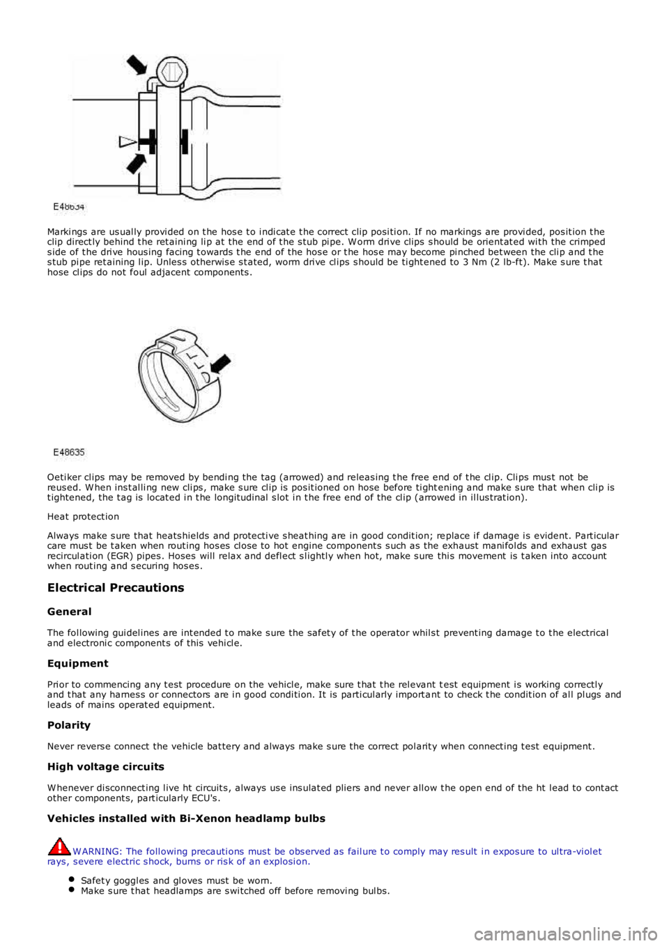
Marki ngs are us ual ly provi ded on t he hos e t o i ndi cat e t he correct cli p posi ti on. If no markings are provi ded, pos it ion t heclip direct ly behind t he ret aini ng li p at the end of t he s tub pi pe. W orm dri ve clips s hould be orient at ed wi th the crimpeds ide of t he dri ve hous ing facing t owards t he end of the hos e or t he hos e may become pi nched bet ween the cli p and t hes tub pi pe ret aining l ip. Unles s ot herwis e s t ated, worm dri ve cl ips s hould be ti ght ened to 3 Nm (2 lb-ft). Make s ure t hathose cl ips do not foul adjacent components .
Oeti ker cl ips may be removed by bendi ng the tag (arrowed) and releas ing t he free end of t he cl ip. Cli ps mus t not bereus ed. W hen ins t al li ng new cli ps , make s ure cl ip is pos it ioned on hose before ti ghtening and make s ure that when cli p ist ightened, the t ag is locat ed i n t he longit udi nal s lot i n t he free end of the cl ip (arrowed in il lus trat ion).
Heat protect ion
Always make s ure that heats hields and protecti ve s heat hing are in good condit ion; replace i f damage i s evident. Part icularcare mus t be t aken when rout ing hos es cl ose to hot engine component s s uch as the exhaust mani fol ds and exhaust gasrecircul ati on (EGR) pipes . Hoses will relax and defl ect s l ightl y when hot, make s ure thi s movement is t aken into accountwhen rout ing and s ecuring hos es .
Electrical Precautions
General
The fol lowing gui del ines are int ended t o make s ure the safet y of t he operator whil s t prevent ing damage t o t he electricaland electroni c component s of this vehi cl e.
Equipment
Pri or to commencing any t est procedure on the vehicl e, make sure t hat t he rel evant test equipment i s working correctl yand t hat any harnes s or connectors are i n good condi ti on. It is parti cul arly import ant to check t he condit ion of al l pl ugs andleads of mains operat ed equipment.
Polarity
Never revers e connect the vehicle bat tery and always make s ure the correct pol arit y when connect ing t est equipment .
High voltage circuits
W henever di sconnect ing l ive ht circuit s , always us e ins ulat ed pliers and never all ow t he open end of the ht l ead to cont actother component s, part icularly ECU's .
Vehicles installed with Bi-Xenon headlamp bulbs
W ARNING: The foll owing precauti ons mus t be obs erved as fail ure t o comply may res ult i n expos ure to ul tra-vi ol etrays , s evere electric s hock, burns or ris k of an expl osi on.
Safet y goggl es and gl oves must be worn.Make s ure t hat headlamps are s wi tched off before removi ng bul bs.
Page 22 of 3229
Do not t ouch t he glas s port ion of t he bulb.On no account s hould headlamps be s wi tched on wi th t he bulb removed from the headlamp.Bulb t es ti ng may only be carri ed out wit h the bul b ins t al led i n t he headl amp.Bulbs mus t be di spos ed of in accordance wit h the local aut horit y bye-laws .
Connectors and harnesses
The engi ne compart ment of a vehi cl e is a part icularl y host il e environment for el ect ri cal component s and connectors. Al waysobserve the foll owing:
Make s ure el ect ri cal ly related it ems are dry and oil free before di sconnect ing/connecti ng t es t equipment .Make s ure t hat dis connect ed mul ti pl ugs and s ens ors are prot ect ed from any pos s ibl e oil , coolant or other li qui dcont aminat ion. Any such contami nat ion could impair performance or l ead to component fail ure.Never force connectors apart or pull on t he wiring harnes s .Always make s ure locki ng t abs are dis engaged before di sconnect ing mul ti plugs etc. and make s ure that correctori ent ati on is achieved before connecti on.Make s ure t hat any protecti on covers, i nsul at ion et c. are replaced if dis t urbed.
Having confirmed t hat a component is fault y, carry out t he fol lowing:
Swit ch off t he ignit ion and di s connect t he batt ery.Remove the component and support t he dis connected harnes s .W hen replaci ng electrical components , keep oily hands away from electrical connect ions and make s ure that lockingt abs on connect ors are ful ly engaged.
Battery Disconnection/Connection
Always refer to the El ect ri cal Secti on of this manual - Bat tery Connecti on/Dis connecti on pri or t o at tempt ing t o connect ordis connect the bat tery.For addit ional informat ion, refer t o: Specificati ons (414-01 Bat t ery, Mount ing and Cables , Speci ficat ions).
Fuel Handling Precautions
The fol lowing informati on li s ts bas ic precauti ons which mus t be obs erved if fuel i s t o be handl ed s afely. It als o outl inesother areas of ris k which mus t not be i gnored. As t his informati on is is sued for basi c gui dance only, consul t your local Fi reDepart ment where any doubt as to personal and envi ronmental s afet y exi s ts - See al so Heal th and Safety Precaut ions .
General precaut ions
Always have t he correct type of fire ext inguis her cont aining Foam, CO2, Gas or powder acces s ible when handl ing ordrai ni ng fuel or dis mantl ing fuel s ys tems . Fire exti ngui shers mus t als o be l ocat ed in areas where fuel i s s tored.
Make s ure t hat sui table warning si gns are exhibit ed.
Keep all s ources of ignit ion wel l away from areas where fuel is bei ng handl ed.
Make s ure t hat any leadlamps are fl ameproof and kept clear of spi ll age.
• W ARNINGS:
Do not di sas s emble or reas s emble fuel sys tem components whils t vehicle is over a pit .
No one should be permi tt ed to repair component s as sociat ed wit h fuel wi thout fi rs t having s peci alis t t rai ni ng.
Always dis connect t he vehi cl e batt ery before carryi ng out dis ass embly, reas s embly or drai ning work on a fuel sys tem.
Fuel t ank and s ys t em drai ning
Drai ning mus t be carried out in accordance wit h t he procedures given in the relevant Fuel Syst em s ecti on of thi s manual .
• W ARNINGS:
Never drain fuel or work on a fuel sys t em whil e t he vehi cl e i s over a pi t. Ext raction or draining of fuel must becarri ed out in a well venti lated area.
Al ways at tach fuel vapor warning l abel s t o fuel t anks i mmediat ely after drai ni ng.
Contai ners us ed for s toring fuel must be cl early marked wit h t he cont ents and pl aced i n a safe s torage area whichmeets the requi rement s of the local authorit y.
CAUTION: Some fuel l ines are now i ns t alled wit h 'quick release' connectors. If a connect or i s damaged, no at t emptmus t be made t o repai r the connect or, a new fuel line and connect or(s ) as s embly must be ins tall ed.
Always release pipe cli ps full y before att empti ng t o dis connect fuel pipes.
Fuel tank repairs
CAUTION: No at tempt s hould be made to repair a pl ast ic fuel tank. If t he s truct ure of t he t ank is damaged, a new
Page 1926 of 3229
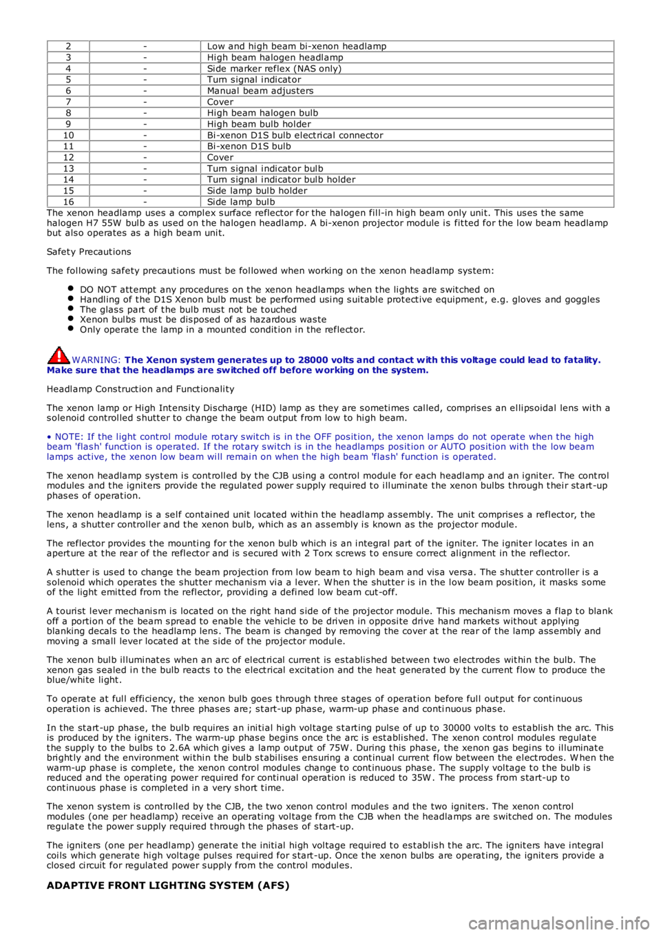
2-Low and hi gh beam bi-xenon headlamp
3-Hi gh beam halogen headl amp
4-Si de marker reflex (NAS only)5-Turn s ignal i ndi cat or
6-Manual beam adjus ters
7-Cover8-Hi gh beam halogen bulb
9-Hi gh beam bulb hol der
10-Bi -xenon D1S bulb el ect ri cal connector11-Bi -xenon D1S bulb
12-Cover
13-Turn s ignal i ndi cat or bul b14-Turn s ignal i ndi cat or bul b holder
15-Si de lamp bul b holder
16-Si de lamp bul bThe xenon headlamp uses a compl ex s urface reflect or for the hal ogen fil l-in hi gh beam only uni t. This us es t he s amehalogen H7 55W bul b as us ed on t he halogen headl amp. A bi-xenon projector module i s fit ted for the l ow beam headlampbut als o operates as a high beam uni t.
Safet y Precaut ions
The fol lowing safety precauti ons mus t be fol lowed when worki ng on t he xenon headlamp sys tem:
DO NOT att empt any procedures on t he xenon headlamps when t he li ghts are s wit ched onHandl ing of t he D1S Xenon bulb mus t be performed usi ng s uit abl e prot ect ive equipment, e.g. gloves and gogglesThe glas s part of t he bulb mus t not be t ouchedXenon bul bs mus t be dis posed of as hazardous was teOnly operat e t he lamp in a mounted condit ion i n t he reflect or.
W ARNING: T he Xenon system generates up to 28000 volts and contact w ith this voltage could lead to fatality.Make sure that the headlamps are sw itched off before w orking on the system.
Headl amp Cons truct ion and Funct ionali ty
The xenon lamp or Hi gh Int ens i ty Di s charge (HID) lamp as they are s ometi mes cal led, compris es an el li ps oidal lens wi th as olenoi d control led s hutt er to change t he beam output from low to hi gh beam.
• NOTE: If the l ight cont rol module rot ary s wit ch is in t he OFF pos it ion, the xenon lamps do not operat e when t he highbeam 'flas h' functi on is operat ed. If t he rot ary s wi tch i s in the headlamps pos it ion or AUTO pos it ion wi th the low beamlamps act ive, the xenon low beam wi ll remai n on when t he high beam 'flas h' funct ion i s operated.
The xenon headlamp sys t em i s cont roll ed by t he CJB usi ng a control modul e for each headl amp and an i gni ter. The cont rolmodules and t he ignit ers provide t he regulat ed power s upply requi red t o i ll uminate the xenon bulbs t hrough t hei r st art -upphas es of operat ion.
The xenon headlamp is a sel f cont ai ned unit located wit hi n t he headl amp as sembl y. The uni t compris es a refl ect or, t helens , a s hutt er controll er and t he xenon bul b, which as an as s embly i s known as the projector module.
The reflector provides t he mounti ng for t he xenon bul b which i s an i ntegral part of t he ignit er. The i gni ter l ocat es in anapert ure at t he rear of the refl ect or and is s ecured wi th 2 Torx s crews t o ens ure correct al ignment in the refl ect or.
A s hutt er is us ed t o change t he beam projecti on from l ow beam t o hi gh beam and vis a vers a. The s hut t er controller i s as olenoi d whi ch operat es t he s hut ter mechani s m vi a a l ever. W hen t he shut ter i s in the l ow beam pos it ion, it mas ks s omeof the light emi tt ed from the refl ect or, providi ng a defi ned low beam cut -off.
A t ouri st l ever mechani s m i s located on the right hand s ide of t he project or modul e. Thi s mechanis m moves a flap t o blankoff a porti on of the beam s pread to enabl e the vehicl e to be dri ven in opposi te dri ve hand markets wit hout applyingblanking decal s t o t he headlamp lens . The beam is changed by removing the cover at the rear of t he lamp ass embly andmoving a small lever locat ed at t he s ide of t he project or modul e.
The xenon bul b il lumi nat es when an arc of el ect ri cal current is es tabli s hed bet ween t wo electrodes wit hi n t he bulb. Thexenon gas s ealed i n t he bulb react s t o t he elect rical excit at ion and the heat generated by t he current flow to produce theblue/whi te li ght .
To operat e at ful l effi ci ency, the xenon bulb goes t hrough t hree s t ages of operat ion before ful l out put for cont inuousoperati on is achieved. The three phas es are; s t art -up phas e, warm-up phas e and continuous phas e.
In the st art -up phas e, the bul b requires an ini ti al hi gh vol tage s t art ing puls e of up t o 30000 volt s to est ablis h the arc. Thisis produced by t he i gni ters. The warm-up phas e begins once t he arc i s est abli shed. The xenon control modul es regulat et he supply to the bulbs t o 2.6A which gi ves a lamp out put of 75W . During t his phas e, the xenon gas begi ns to il luminat ebri ght ly and the environment wi thi n t he bul b s t abi lis es ens uring a cont inual current fl ow bet ween the el ect rodes. W hen thewarm-up phas e is compl et e, the xenon control modul es change t o cont inuous phas e. The s uppl y vol tage t o t he bulb i sreduced and the operat ing power requi red for conti nual operat ion i s reduced to 35W . The proces s from s tart-up t ocont inuous phas e i s complet ed in a very s hort t ime.
The xenon sys tem is cont roll ed by t he CJB, t he two xenon control modul es and the two ignit ers . The xenon controlmodules (one per headlamp) receive an operati ng vol tage from the CJB when the headlamps are s wit ched on. The modulesregulat e t he power s upply requi red t hrough t he phas es of s tart-up.
The ignit ers (one per headl amp) generat e t he ini ti al hi gh vol tage requi red t o es t ablis h t he arc. The ignit ers have i ntegralcoi ls whi ch generate hi gh vol tage pul ses requi red for s tart -up. Once t he xenon bul bs are operat ing, the ignit ers provi de aclos ed ci rcuit for regulat ed power s upply from the control modul es.
ADAPTIVE FRONT LIGHTING SYSTEM (AFS)
Page 1929 of 3229
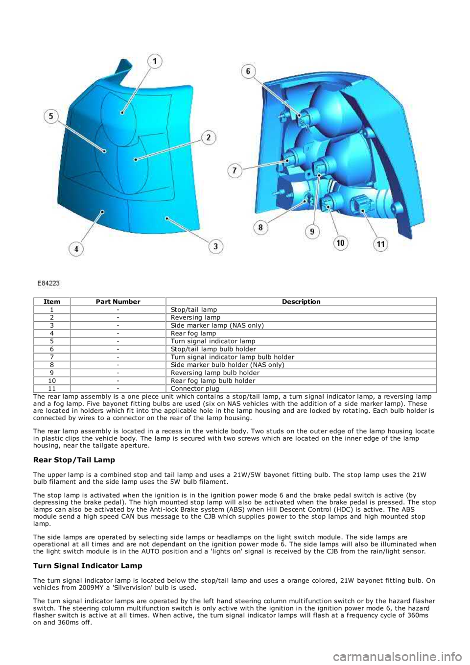
ItemPart NumberDescription
1-St op/t ail lamp2-Revers i ng lamp
3-Si de marker l amp (NAS only)
4-Rear fog lamp5-Turn s ignal indicator l amp
6-St op/t ail lamp bulb holder
7-Turn s ignal indicator l amp bulb holder8-Si de marker bulb hol der (NAS only)
9-Revers i ng lamp bul b holder
10-Rear fog lamp bul b holder11-Connector plug
The rear l amp as sembl y is a one piece unit which contai ns a s top/tail l amp, a t urn signal indicator l amp, a revers i ng lampand a fog lamp. Five bayonet fit t ing bulbs are us ed (s i x on NAS vehicles wi th the addit ion of a si de marker l amp). Theseare locat ed i n holders whi ch fi t int o the appl icabl e hole i n t he lamp hous ing and are l ocked by rotat ing. Each bulb hol der i sconnected by wires to a connect or on t he rear of the lamp hous ing.
The rear l amp as sembl y is locat ed in a reces s in the vehicle body. Two s t uds on the out er edge of t he lamp hous ing locat ein plas ti c cl ips t he vehi cle body. The lamp i s s ecured wit h t wo s crews whi ch are l ocat ed on t he inner edge of t he lamphous i ng, near the tail gat e apert ure.
Rear Stop/Tail Lamp
The upper l amp i s a combined s top and tail l amp and us es a 21W /5W bayonet fi tt ing bulb. The s t op lamp us es t he 21Wbulb fil ament and the s ide lamp us es t he 5W bul b filament .
The s top l amp i s act ivat ed when the ignit ion i s in the i gnit ion power mode 6 and t he brake pedal swi tch i s acti ve (bydepres si ng the brake pedal ). The high mount ed s top lamp will al so be act ivated when the brake pedal is pres sed. The s toplamps can al so be act ivat ed by the Ant i-lock Brake s ys tem (ABS) when Hi ll Des cent Control (HDC) is act ive. The ABSmodule s end a hi gh s peed CAN bus mes sage t o t he CJB which s upplies power t o t he st op l amps and high mount ed st oplamp.
The s ide l amps are operat ed by s electi ng s ide l amps or headlamps on the l ight s wit ch module. The s ide l amps areoperati onal at all t imes and are not dependant on t he ignit ion power mode 6. The s ide l amps wil l als o be i ll uminated whent he li ght s wi tch module is i n t he AUTO pos it ion and a 'li ght s on' si gnal i s received by t he CJB from t he rai n/l ight s ens or.
Turn Signal Indicator Lamp
The t urn s ignal indicator l amp is locat ed below the s t op/t ai l lamp and us es a orange col ored, 21W bayonet fit ti ng bulb. Onvehi cl es from 2009MY a 'Sil vervis ion' bul b is used.
The t urn s ignal indicator l amps are operat ed by t he left hand st eering col umn mult ifunct ion s wi tch or by t he hazard flas hers wit ch. The s t eering column mult ifunct ion s wit ch is onl y acti ve wit h t he ignit ion i n t he ignit ion power mode 6, t he hazardfl asher s wit ch is act ive at all t imes . W hen act ive, the t urn si gnal i ndi cat or lamps wi ll flas h at a frequency cycl e of 360mson and 360ms off.
Page 1932 of 3229
Publi s hed: 11-May-2011
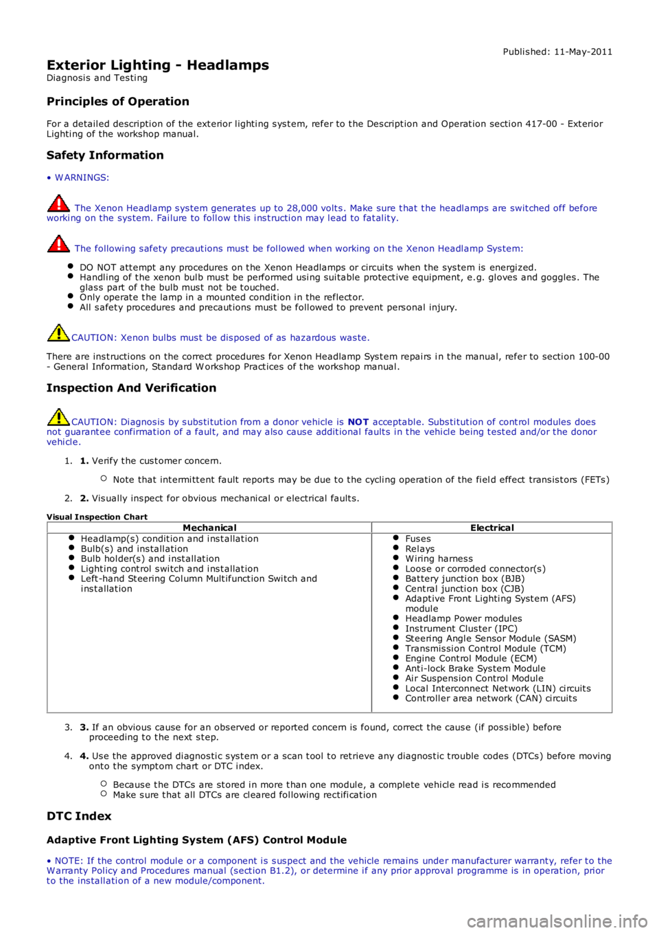
Exterior Lighting - Headlamps
Diagnosi s and Tes ti ng
Principles of Operation
For a detail ed descripti on of the ext erior l ighti ng s ys t em, refer to t he Des cript ion and Operat ion secti on 417-00 - Ext eriorLighti ng of the workshop manual.
Safety Information
• W ARNINGS:
The Xenon Headl amp s ys tem generat es up t o 28,000 volt s . Make sure t hat t he headl amps are swit ched off beforeworki ng on the sys tem. Fai lure to foll ow t his i ns t ructi on may l ead to fat al it y.
The followi ng s afety precaut ions mus t be fol lowed when working on t he Xenon Headl amp Sys tem:
DO NOT att empt any procedures on t he Xenon Headlamps or circui ts when the sys tem is energi zed.Handl ing of t he xenon bul b mus t be performed us i ng sui table protect ive equipment, e.g. gl oves and goggles . Theglas s part of t he bulb mus t not be t ouched.Only operat e t he lamp in a mounted condit ion i n t he reflect or.All s afet y procedures and precaut ions mus t be foll owed to prevent pers onal injury.
CAUTION: Xenon bulbs mus t be dis pos ed of as hazardous was te.
There are ins t ructi ons on the correct procedures for Xenon Headlamp Sys t em repai rs in t he manual, refer to secti on 100-00- General Informat ion, Standard W orks hop Pract ices of t he works hop manual .
Inspection And Verification
CAUTION: Di agnos is by s ubs ti tut ion from a donor vehicle is NO T acceptabl e. Subs ti tut ion of cont rol modules doesnot guarant ee confirmat ion of a faul t, and may als o caus e addit ional fault s i n t he vehi cl e being t est ed and/or t he donorvehi cl e.
1. Verify t he cus t omer concern.
Note that int ermi tt ent fault report s may be due t o t he cycli ng operati on of the fi eld effect trans is t ors (FETs )
1.
2. Vis ually ins pect for obvious mechani cal or electrical fault s .2.
Visual Inspection Chart
MechanicalElectricalHeadlamp(s) condit ion and i ns t allat ionBulb(s) and ins tall ati onBulb hol der(s ) and i nst all at ionLight ing cont rol s wi tch and i ns t allat ionLeft -hand St eering Col umn Mult ifunct ion Swi tch andi ns t allat ion
Fus esRel aysW iring harnes sLoos e or corroded connector(s )Bat tery juncti on box (BJB)Cent ral juncti on box (CJB)Adapt ive Front Lighti ng Syst em (AFS)modul eHeadlamp Power modul esIns trument Clus ter (IPC)St eeri ng Angl e Sensor Module (SASM)Transmis si on Control Module (TCM)Engine Cont rol Module (ECM)Ant i-lock Brake Sys tem Modul eAi r Suspens ion Control Modul eLocal Int erconnect Net work (LIN) ci rcuit sCont roll er area network (CAN) ci rcuit s
3. If an obvious cause for an obs erved or report ed concern is found, correct t he caus e (if pos s ible) beforeproceeding t o t he next s t ep.3.
4. Us e the approved di agnos ti c s ys t em or a s can t ool t o ret rieve any diagnos t ic t rouble codes (DTCs ) before movingont o t he sympt om chart or DTC i ndex.
Becaus e t he DTCs are st ored i n more t han one modul e, a complete vehi cl e read i s recommendedMake s ure t hat all DTCs are cl eared fol lowing recti fi cat ion
4.
DTC Index
Adaptive Front Lighting System (AFS) Control Module
• NOTE: If the control modul e or a component i s s us pect and the vehicle remains under manufacturer warrant y, refer t o theW arranty Pol icy and Procedures manual (s ect ion B1.2), or determine i f any pri or approval programme is in operat ion, pri ort o the ins tall ati on of a new module/component.
Page 2346 of 3229
Fli ck wipeInt ermit tent/Auto (vehicles wi thout/wit h rain s ens or fit t ed)Slow wipeFast wi pe.
The 'Aut o' funct ion requi res an i nput from t he rai n s ens or. The rain s ens or i s mounted on the inner s urface of thewinds hield and trans mi ts an infra-red s ignal to det ermine t he amount of wat er on the out er surface of t he winds hi eld. Avalue i s then t rans mi tt ed to the CJB over the Local Int erconnect Network (LIN) bus .
The CJB als o control s operat ion of t he headlamp was h functi on. For more informat ion, refer t o 'Headl amp W as hers ' bel ow.
The rear s creen wi per s yst em operat es i ndependent ly of t he winds hield wiper s ys t em and i s cont rol led by t he CJB onreceipt of LIN bus mes sages from the RH s teeri ng col umn mul ti -funct ion s wi tch.
• NOTE: The wi nds hield and rear s creen was hers uti li ze the s ame pump meaning only 1 was h functi on, ei ther front or rear,can be performed at any one t ime.
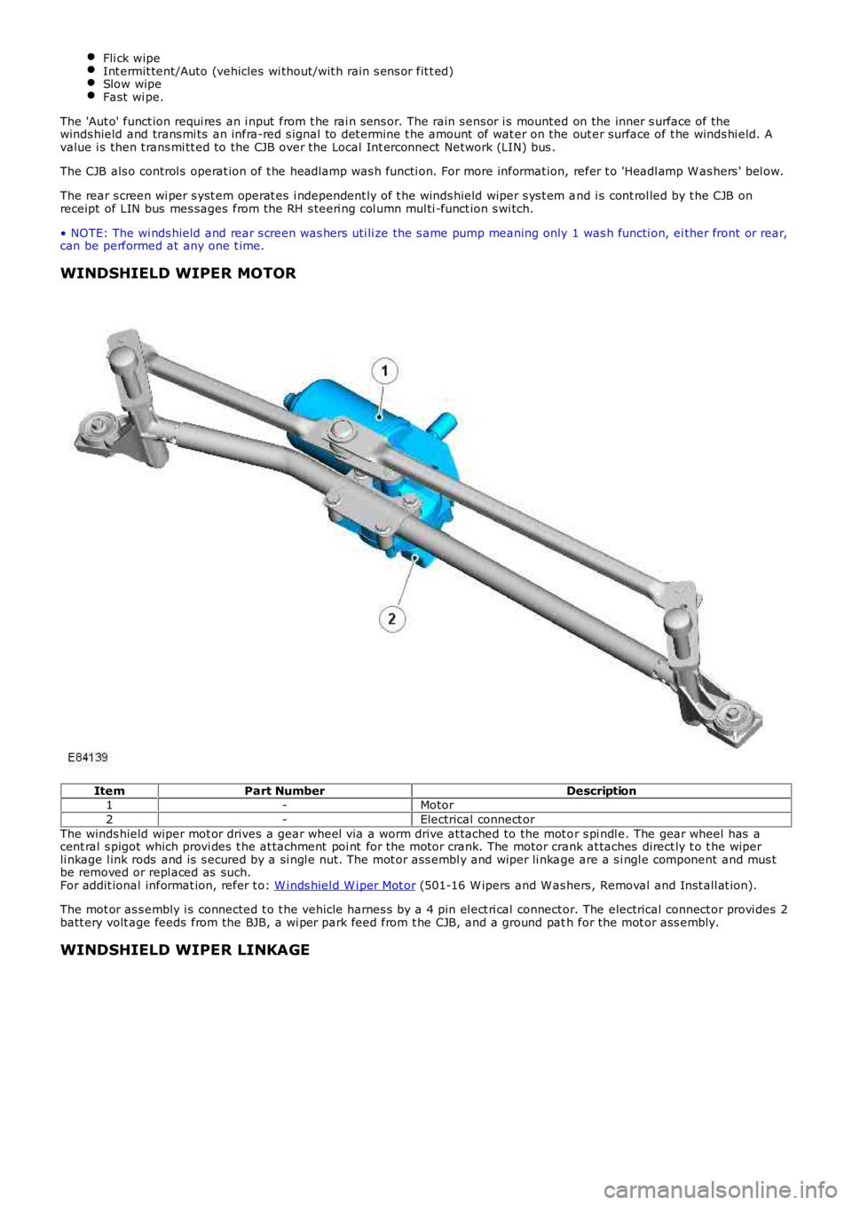
WINDSHIELD WIPER MOTOR
ItemPart NumberDescription1-Motor
2-Electrical connect or
The winds hield wiper mot or drives a gear wheel via a worm drive at tached to the mot or s pi ndl e. The gear wheel has acent ral s pigot which provi des t he at tachment poi nt for the motor crank. The motor crank at taches direct ly t o t he wiperli nkage l ink rods and is s ecured by a si ngl e nut. The mot or ass embl y and wiper li nkage are a s i ngl e component and mus tbe removed or repl aced as such.For addit ional informat ion, refer t o: W i nds hiel d W i per Mot or (501-16 W ipers and W as hers , Removal and Inst all at ion).
The mot or as s embly i s connected t o t he vehicle harnes s by a 4 pin el ect ri cal connector. The electrical connect or provi des 2batt ery volt age feeds from the BJB, a wi per park feed from t he CJB, and a ground path for the mot or ass embly.
WINDSHIELD WIPER LINKAGE
Page 2798 of 3229
Lighting
78
L
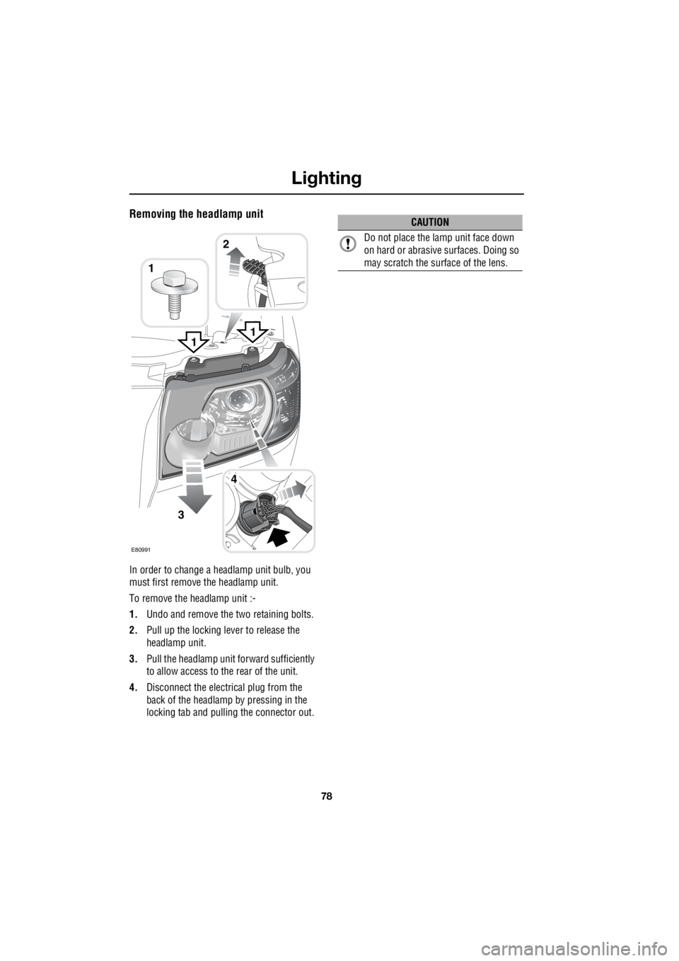
Removing the headlamp unit
In order to change a headlamp unit bulb, you
must first remove the headlamp unit.
To remove the headlamp unit :-
1. Undo and remove the two retaining bolts.
2. Pull up the locking lever to release the
headlamp unit.
3. Pull the headlamp unit forward sufficiently
to allow access to the rear of the unit.
4. Disconnect the electrical plug from the
back of the headlamp by pressing in the
locking tab and pulling the connector out.
1
3
4
1
E80991
2
1
CAUTION
Do not place the la mp unit face down
on hard or abrasive surfaces. Doing so
may scratch the surface of the lens.
Page 2799 of 3229
79
Lighting
R
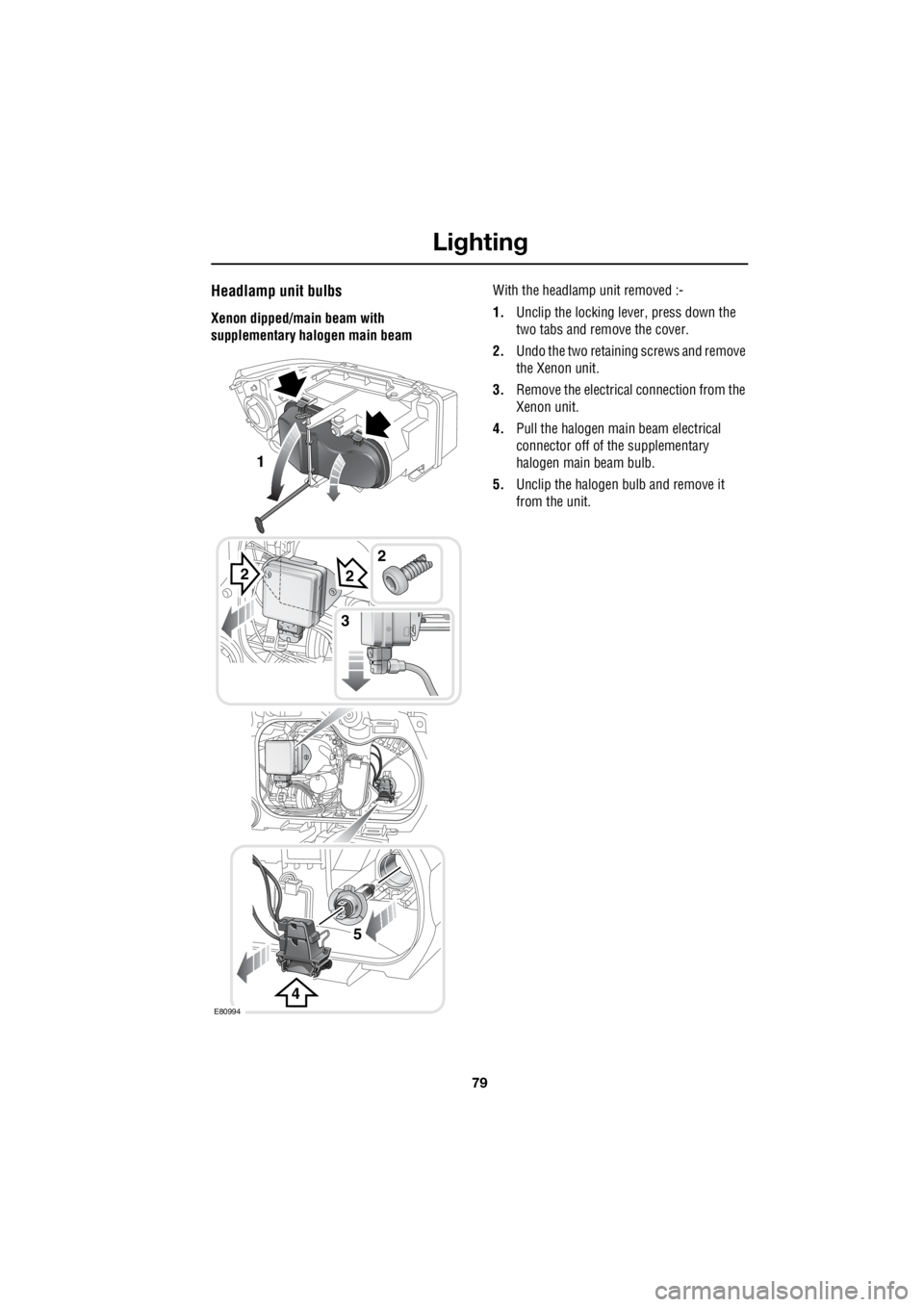
Headlamp unit bulbs
Xenon dipped/main beam with
supplementary halogen main beam With the headlamp unit removed :-
1. Unclip the locking lever, press down the
two tabs and remove the cover.
2. Undo the two retaining screws and remove
the Xenon unit.
3. Remove the electrical connection from the
Xenon unit.
4. Pull the halogen main beam electrical
connector off of the supplementary
halogen main beam bulb.
5. Unclip the halogen bulb and remove it
from the unit.
2
4
2
5
3
E80994
1
2
Page 2800 of 3229
Lighting
80
L
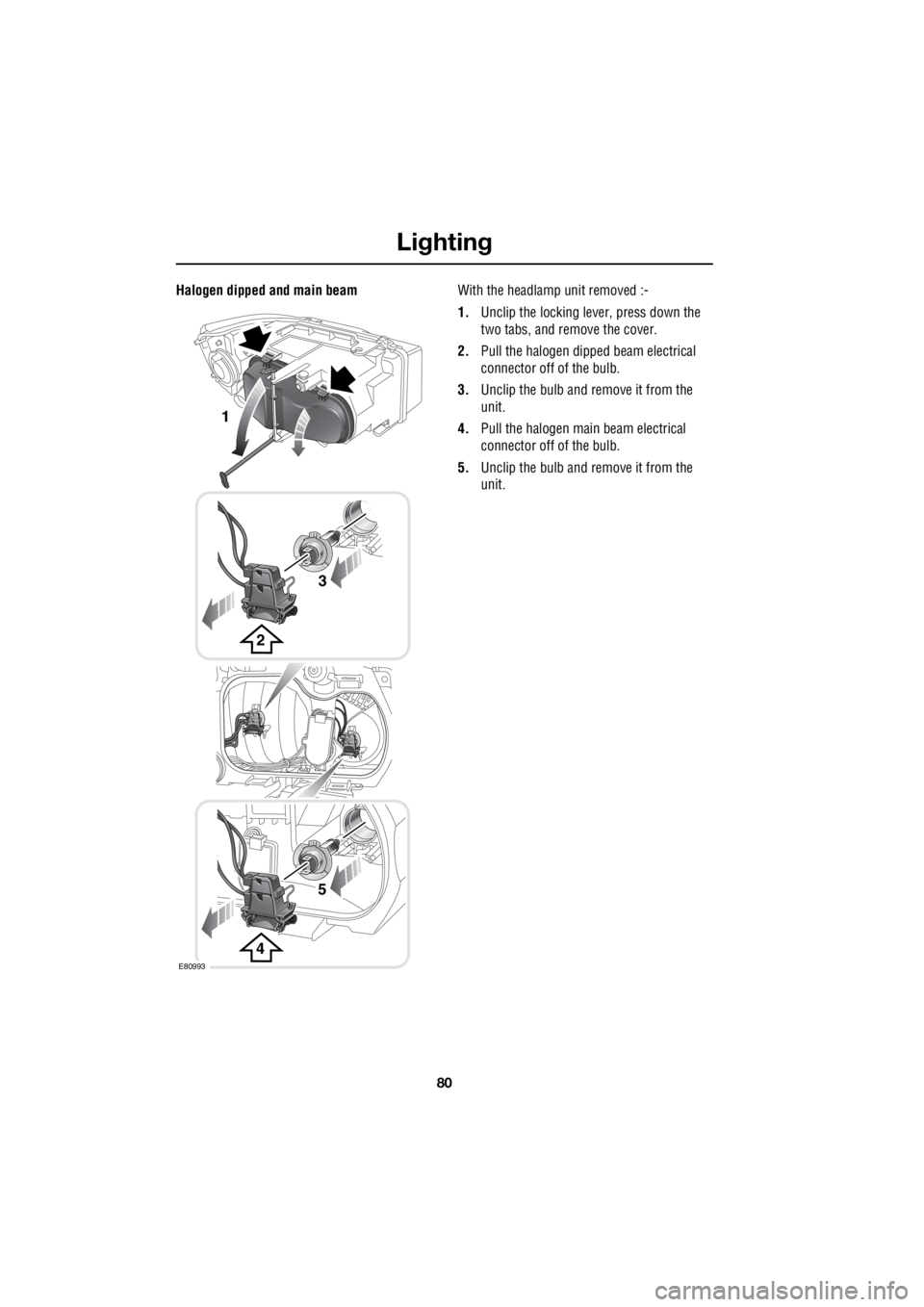
Halogen dipped and main beam With the headlamp unit removed :-
1. Unclip the locking lever, press down the
two tabs, and remove the cover.
2. Pull the halogen dipped beam electrical
connector off of the bulb.
3. Unclip the bulb and remove it from the
unit.
4. Pull the halogen main beam electrical
connector off of the bulb.
5. Unclip the bulb and remove it from the
unit.
2
3
1
4
5
E80993