ABS Lexus CT200h 2013 (in English) User Guide
[x] Cancel search | Manufacturer: LEXUS, Model Year: 2013, Model line: CT200h, Model: Lexus CT200h 2013Pages: 688
Page 272 of 688
2724-5. Using the driving support systems
CT200h_OM_OM76102E_(EE)
WA R N I N G
The ABS does not operate effectively when
The limits of tire gripping performance have been exceeded (such as exces-
sively worn tires on a snow covered road).
The vehicle hydroplanes while driving at high speed on wet or slick road.
Stopping distance when the ABS is operating may exceed that of normal condi-
tions
The ABS is not designed to shorten the vehicle’s stopping distance. Always
maintain a safe distance from the vehicle in front of you, especially in the fol-
lowing situations:
When driving on dirt, gravel or snow-covered roads
When driving with tire chains
When driving over bumps in the road
When driving over roads with potholes or uneven surfaces
TRC may not operate effectively when
Directional control and power may not be achievable while driving on slippery
road surfaces, even if the TRC system is operating.
Drive the vehicle carefully in conditions where stability and power may be lost.
When the VSC is activated
The slip indicator light flashes. Always drive carefully. Reckless driving may
cause an accident. Exercise particular care when the indicator light flashes.
When the TRC system is turned off
Be especially careful and drive at a speed appropriate to the road conditions. As
these are the system to help ensure vehicle stability and driving force, do not
turn the TRC system off unless necessary.
Replacing tires
Make sure that all tires are of the specified size and of the same brand, tread
pattern and total load capacity. In addition, make sure that the tires are inflated
to the recommended tire inflation pressure level.
The ABS, VSC and TRC systems will not function correctly if different tires
are installed on the vehicle.
Contact any authorized Lexus dealer or repairer, or another duly qualified and
equipped professional for further information when replacing tires or wheels.
Handling of tires and the suspension
Using tires with any kind of problem or modifying the suspension will affect
the driving assist systems, and may cause a system to malfunction.
Page 281 of 688

2814-5. Using the driving support systems
4
Driving
CT200h_OM_OM76102E_(EE)
WA R N I N G
Limitations of the pre-crash safety system
Do not overly rely on the pre-crash safety system. Always drive safely, taking
care to observe your surroundings and checking for any obstacles or other road
hazards.
Failure to do so may cause an accident resulting in death or serious injury.
Cautions regarding the assist contents of the system
By means of alarms and brake control, the pre-crash safety system is intended
to assist the driver in avoiding collisions through the process of LOOK-
JUDGE-ACT. There are limits to the degree of assistance the system can pro-
vide, so please keep in mind the following important points.
Assisting the driver in watching the road
The pre-crash safety system is only able to detect obstacles directly in front of
the vehicle, and only within a limited range. It is not a mechanism that allows
careless or inattentive driving, and it is not a system that can assist the driver
in low-visibility conditions. It is still necessary for the driver to pay close
attention to the vehicle’s surroundings.
Assisting the driver in making correct judgement
When attempting to estimate the possibility of a collision, the only data avail-
able to the pre-crash safety system is that from obstacles it has detected
directly in front of the vehicle. Therefore, it is absolutely necessary for the
driver to remain vigilant and to determine whether or not there is a possibility
of collision in any given situation.
Assisting the driver in taking action
The pre-crash safety system’s braking assist feature is designed to help reduce
the severity of a collision, and so only acts when the system has judged that a
collision is unavoidable. This system by itself is not capable of automatically
avoiding a collision or bringing the vehicle to a stop safely. For this reason,
when encountering a dangerous situation the driver must take direct and
immediate action in order to ensure the safety of all involved.
Page 510 of 688
5067-3. Do-it-yourself maintenance
CT200h_OM_OM76102E_(EE)
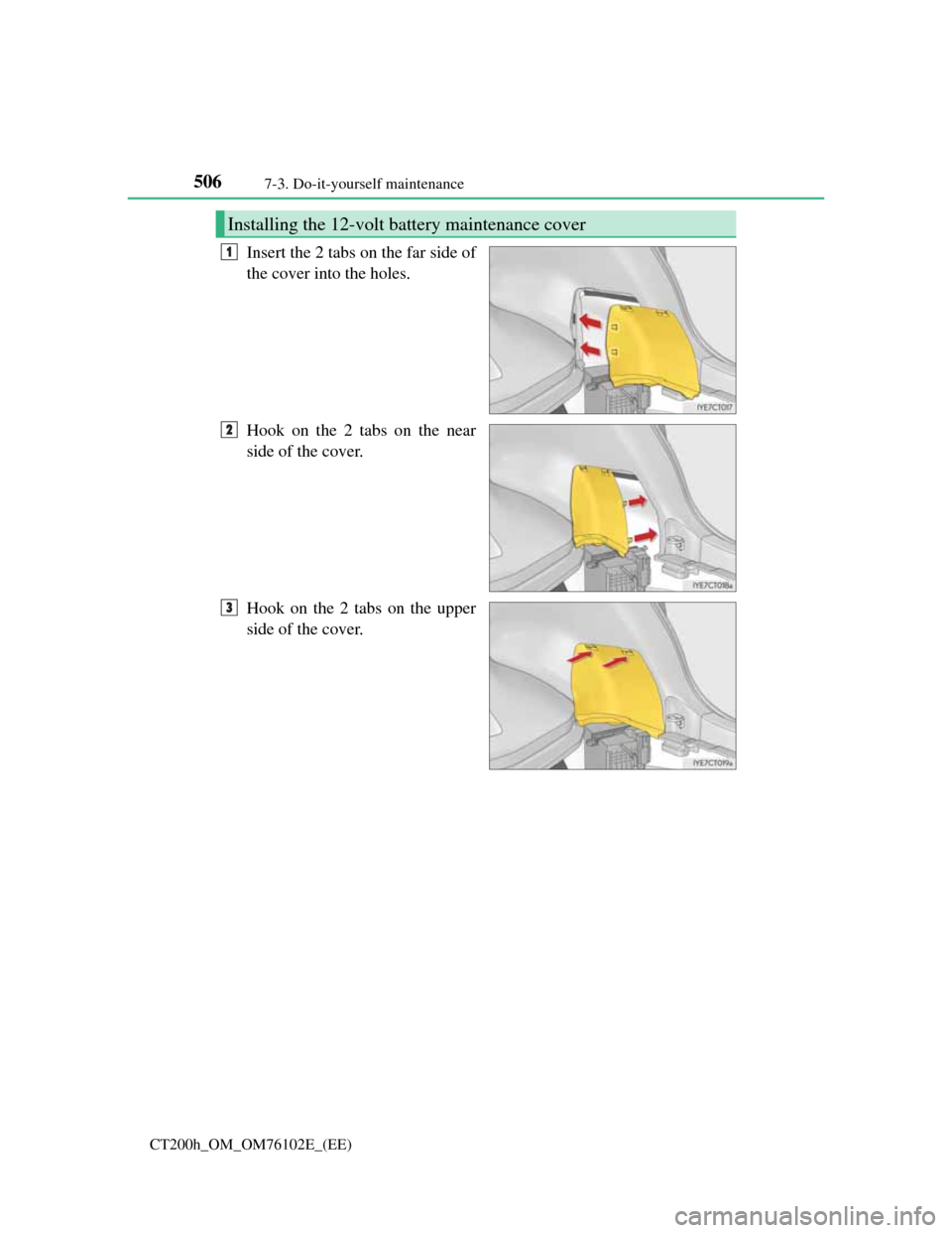
Insert the 2 tabs on the far side of
the cover into the holes.
Hook on the 2 tabs on the near
side of the cover.
Hook on the 2 tabs on the upper
side of the cover.
Installing the 12-volt battery maintenance cover
1
2
3
Page 544 of 688
5407-3. Do-it-yourself maintenance
CT200h_OM_OM76102E_(EE)
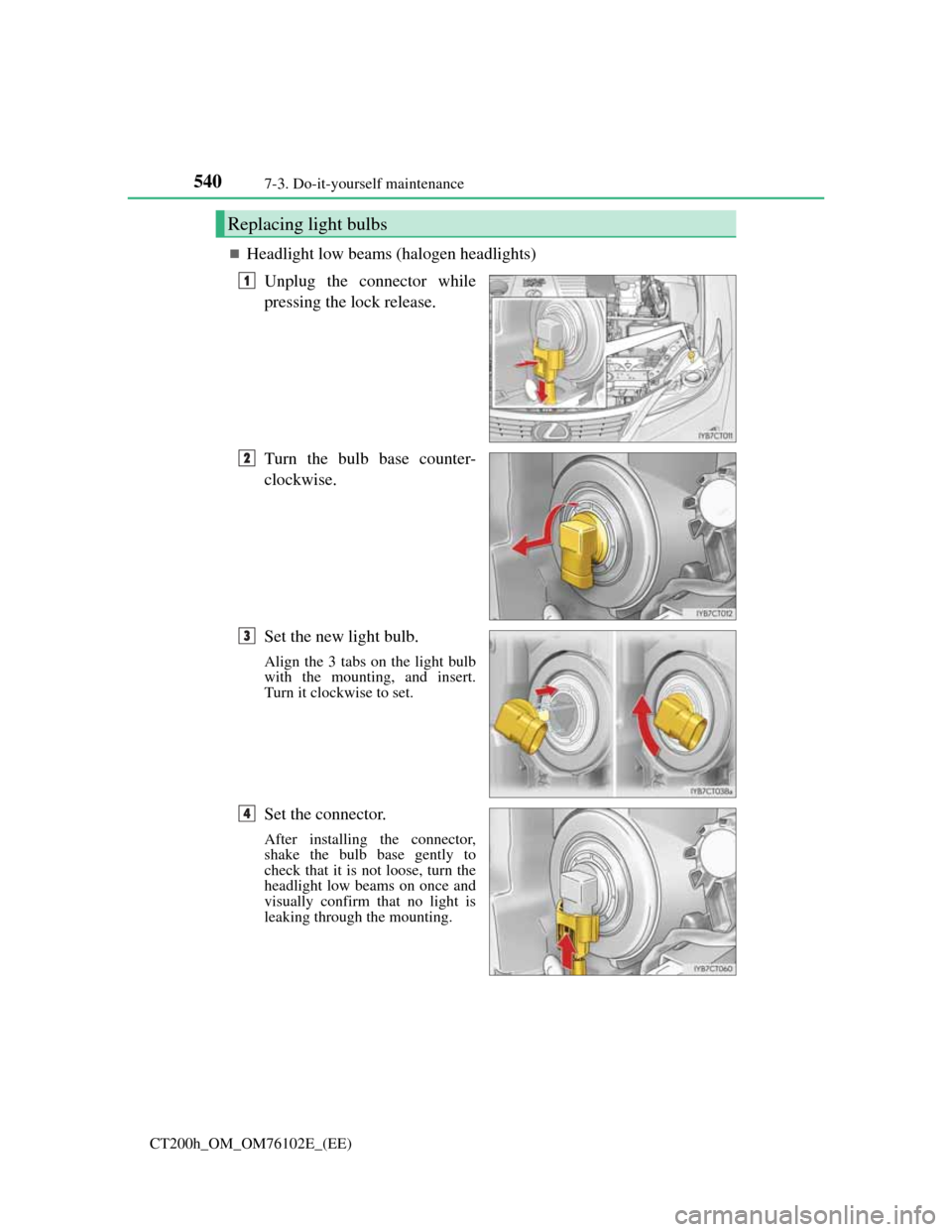
Headlight low beams (halogen headlights)
Unplug the connector while
pressing the lock release.
Turn the bulb base counter-
clockwise.
Set the new light bulb.
Align the 3 tabs on the light bulb
with the mounting, and insert.
Turn it clockwise to set.
Set the connector.
After installing the connector,
shake the bulb base gently to
check that it is not loose, turn the
headlight low beams on once and
visually confirm that no light is
leaking through the mounting.
Replacing light bulbs
1
2
3
4
Page 546 of 688
5427-3. Do-it-yourself maintenance
CT200h_OM_OM76102E_(EE)
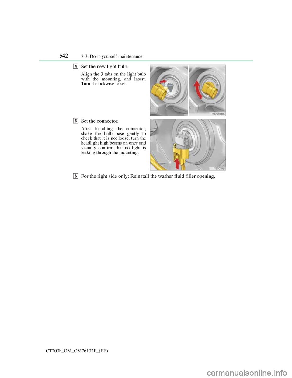
Set the new light bulb.
Align the 3 tabs on the light bulb
with the mounting, and insert.
Turn it clockwise to set.
Set the connector.
After installing the connector,
shake the bulb base gently to
check that it is not loose, turn the
headlight high beams on once and
visually confirm that no light is
leaking through the mounting.
For the right side only: Reinstall the washer fluid filler opening.
4
5
6
Page 548 of 688
5447-3. Do-it-yourself maintenance
CT200h_OM_OM76102E_(EE)
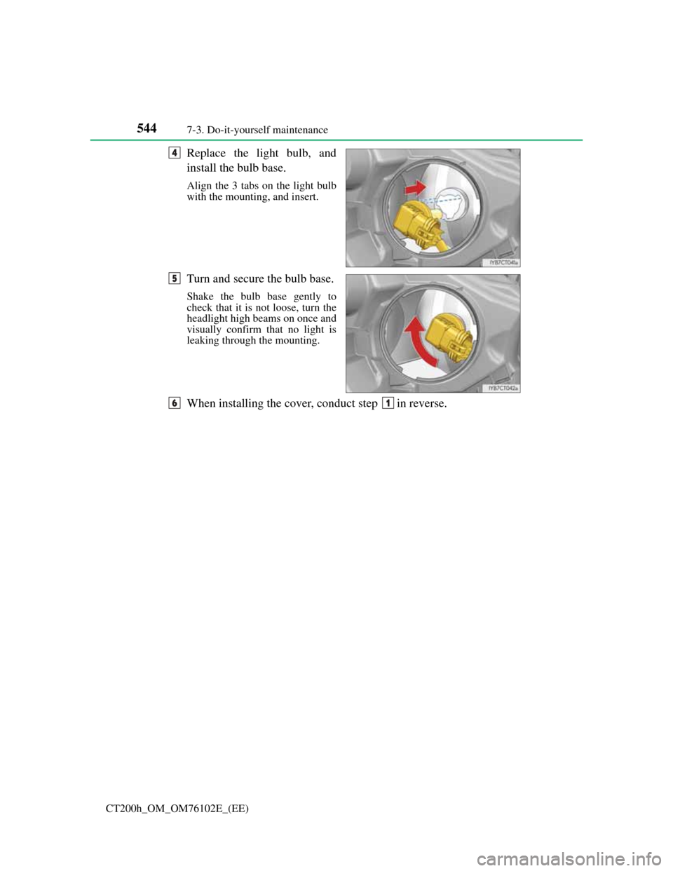
Replace the light bulb, and
install the bulb base.
Align the 3 tabs on the light bulb
with the mounting, and insert.
Turn and secure the bulb base.
Shake the bulb base gently to
check that it is not loose, turn the
headlight high beams on once and
visually confirm that no light is
leaking through the mounting.
When installing the cover, conduct step in reverse.
4
5
61
Page 550 of 688
5467-3. Do-it-yourself maintenance
CT200h_OM_OM76102E_(EE)
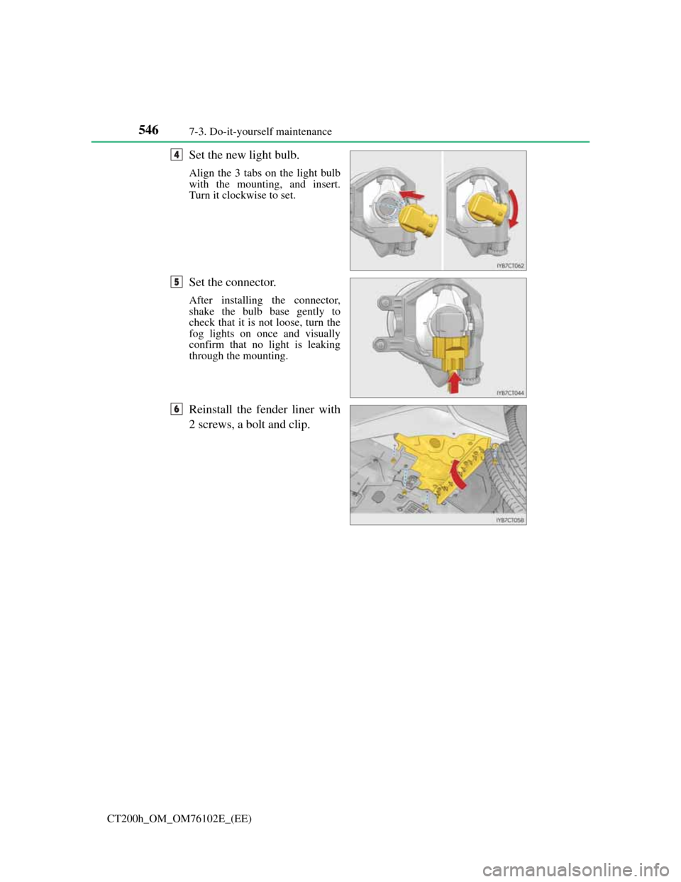
Set the new light bulb.
Align the 3 tabs on the light bulb
with the mounting, and insert.
Turn it clockwise to set.
Set the connector.
After installing the connector,
shake the bulb base gently to
check that it is not loose, turn the
fog lights on once and visually
confirm that no light is leaking
through the mounting.
Reinstall the fender liner with
2 screws, a bolt and clip.
4
5
6
Page 556 of 688
5527-3. Do-it-yourself maintenance
CT200h_OM_OM76102E_(EE)
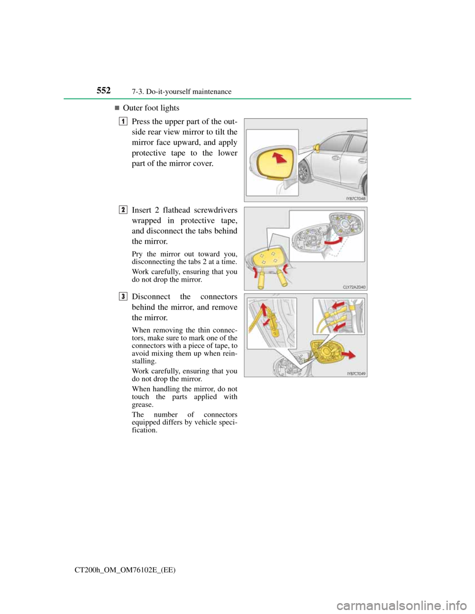
Outer foot lights
Press the upper part of the out-
side rear view mirror to tilt the
mirror face upward, and apply
protective tape to the lower
part of the mirror cover.
Insert 2 flathead screwdrivers
wrapped in protective tape,
and disconnect the tabs behind
the mirror.
Pry the mirror out toward you,
disconnecting the tabs 2 at a time.
Work carefully, ensuring that you
do not drop the mirror.
Disconnect the connectors
behind the mirror, and remove
the mirror.
When removing the thin connec-
tors, make sure to mark one of the
connectors with a piece of tape, to
avoid mixing them up when rein-
stalling.
Work carefully, ensuring that you
do not drop the mirror.
When handling the mirror, do not
touch the parts applied with
grease.
The number of connectors
equipped differs by vehicle speci-
fication.
1
2
3
Page 558 of 688
5547-3. Do-it-yourself maintenance
CT200h_OM_OM76102E_(EE)
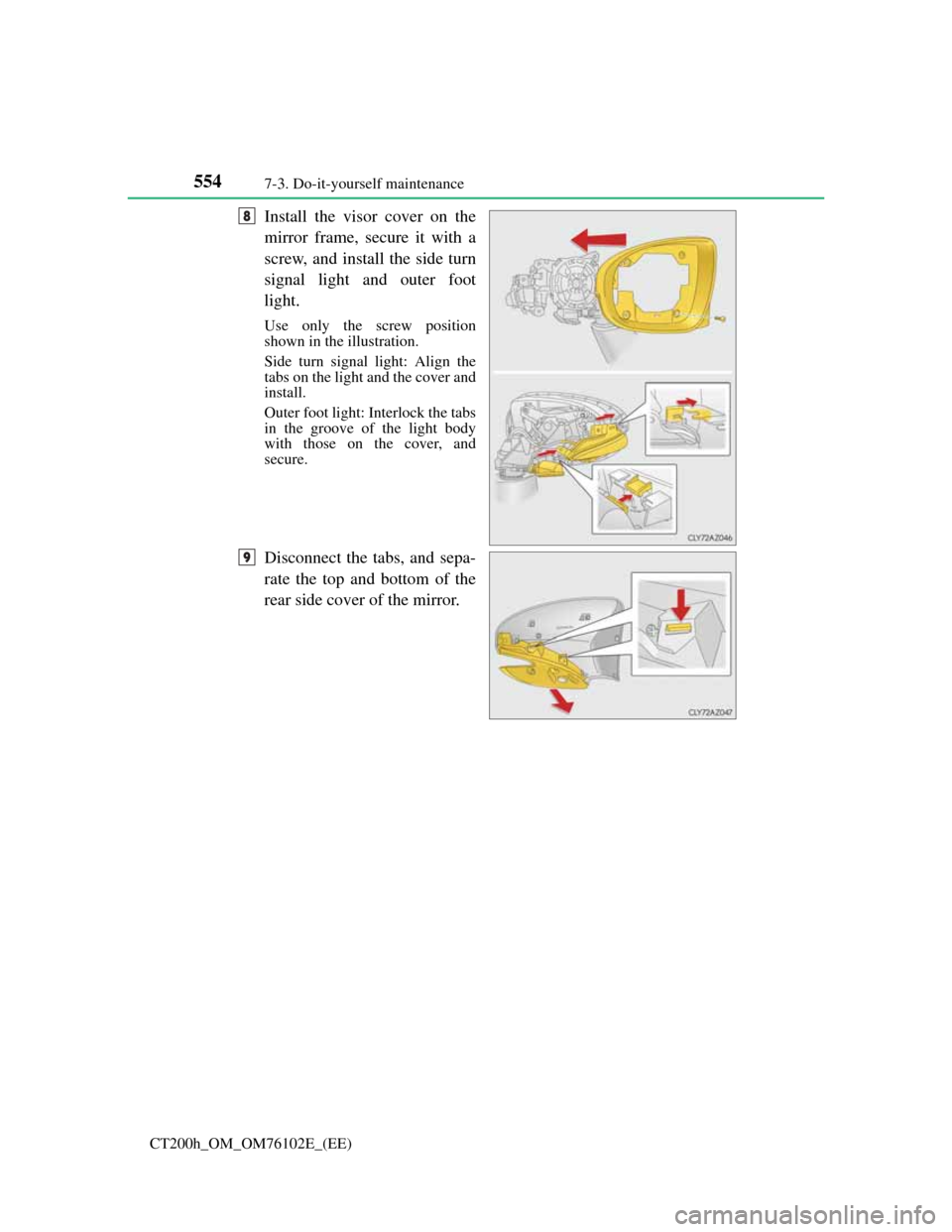
Install the visor cover on the
mirror frame, secure it with a
screw, and install the side turn
signal light and outer foot
light.
Use only the screw position
shown in the illustration.
Side turn signal light: Align the
tabs on the light and the cover and
install.
Outer foot light: Interlock the tabs
in the groove of the light body
with those on the cover, and
secure.
Disconnect the tabs, and sepa-
rate the top and bottom of the
rear side cover of the mirror.
8
9
Page 559 of 688
5557-3. Do-it-yourself maintenance
CT200h_OM_OM76102E_(EE)
7
Maintenance and care
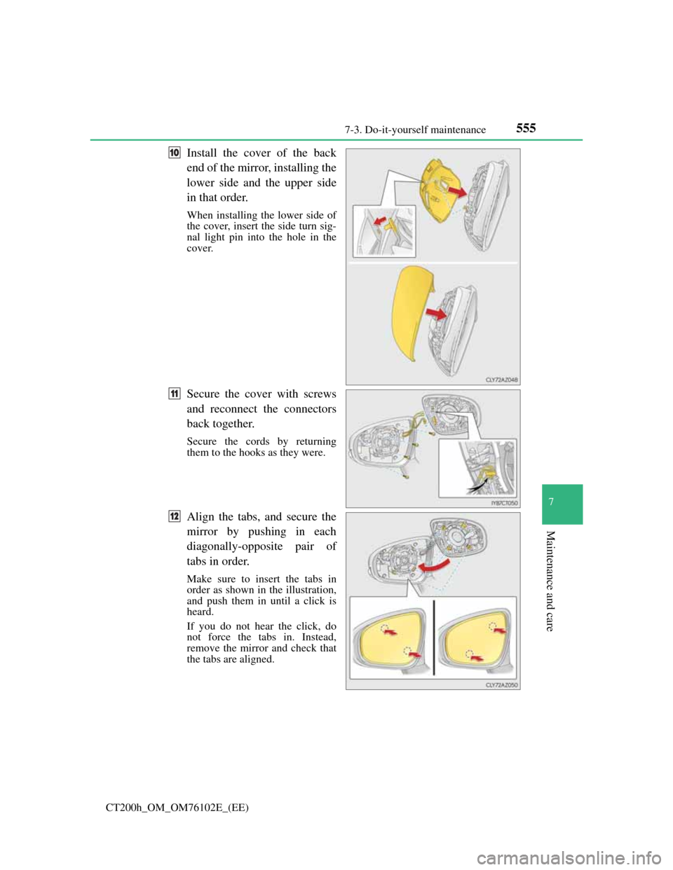
Install the cover of the back
end of the mirror, installing the
lower side and the upper side
in that order.
When installing the lower side of
the cover, insert the side turn sig-
nal light pin into the hole in the
cover.
Secure the cover with screws
and reconnect the connectors
back together.
Secure the cords by returning
them to the hooks as they were.
Align the tabs, and secure the
mirror by pushing in each
diagonally-opposite pair of
tabs in order.
Make sure to insert the tabs in
order as shown in the illustration,
and push them in until a click is
heard.
If you do not hear the click, do
not force the tabs in. Instead,
remove the mirror and check that
the tabs are aligned.
10
11
12