display Lexus IS F 2010 Audio/video System / LEXUS 2010 IS F (OM53A25U) Owner's Manual
[x] Cancel search | Manufacturer: LEXUS, Model Year: 2010, Model line: IS F, Model: Lexus IS F 2010Pages: 543, PDF Size: 16.07 MB
Page 143 of 543
143
2-2. Instrument cluster
2
When driving
Indicators and warning lights
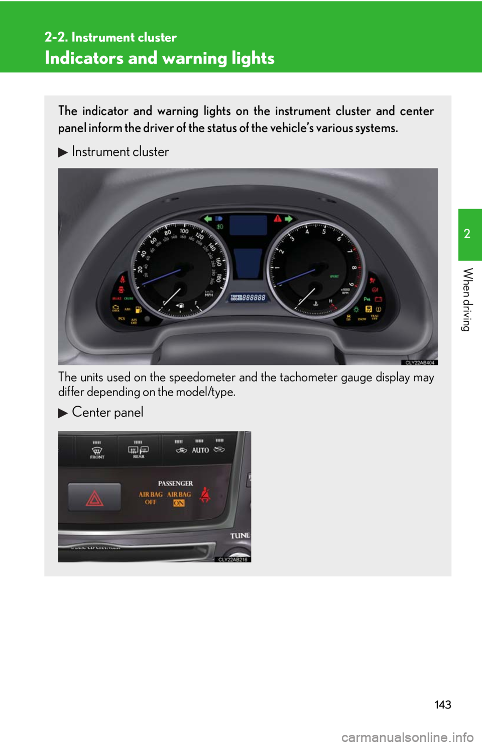
The indicator and warning lights on the instrument cluster and center
panel inform the driver of the status of the vehicle’s various systems.
Instrument cluster
The units used on the speedometer and the tachometer gauge display may
differ depending on the model/type.
Center panel
Page 146 of 543
146
2-2. Instrument cluster
Multi-information display
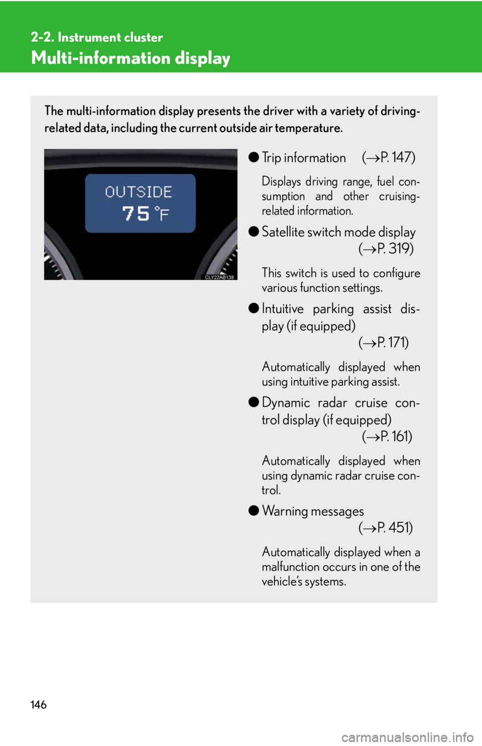
The multi-information display presents the driver with a variety of driving-
related data, including the current outside air temperature.
●Trip information (P. 147)
Displays driving range, fuel con-
sumption and other cruising-
related information.
●Satellite switch mode display
(P. 319)
This switch is used to configure
various function settings.
●Intuitive parking assist dis-
play (if equipped)
(P. 171)
Automatically displayed when
using intuitive parking assist.
●Dynamic radar cruise con-
trol display (if equipped)
(P. 161)
Automatically displayed when
using dynamic radar cruise con-
trol.
●Warning messages
(P. 4 5 1 )
Automatically displayed when a
malfunction occurs in one of the
vehicle’s systems.
Page 147 of 543
147
2-2. Instrument cluster
2
When driving
Trip information
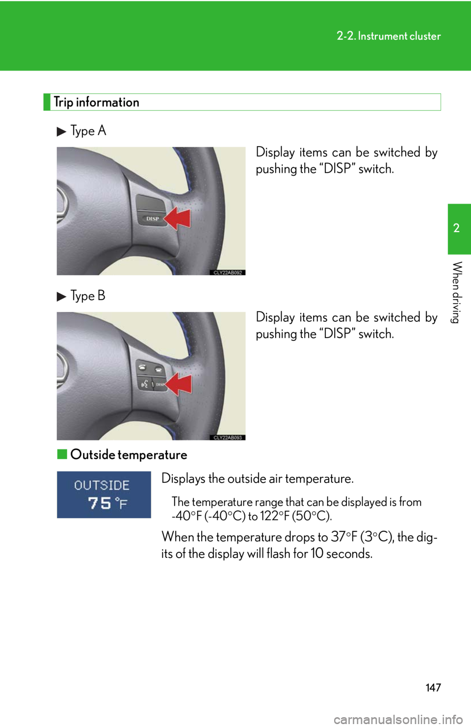
Type A
Display items can be switched by
pushing the “DISP” switch.
Type B
Display items can be switched by
pushing the “DISP” switch.
■Outside temperature
Displays the outside air temperature.
The temperature range that can be displayed is from
-40F (-40C) to 122F (50C).
When the temperature drops to 37F (3C), the dig-
its of the display will flash for 10 seconds.
Page 148 of 543
148
2-2. Instrument cluster
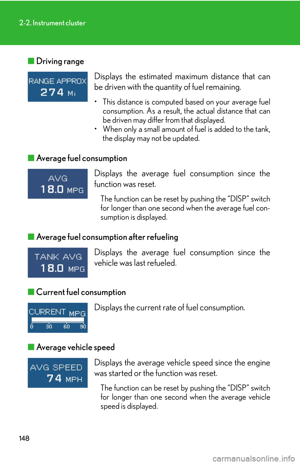
■Driving range
■Average fuel consumption
■Average fuel consumption after refueling
■Current fuel consumption
■Average vehicle speed Displays the estimated maximum distance that can
be driven with the quantity of fuel remaining.
• This distance is computed based on your average fuel
consumption. As a result, the actual distance that can
be driven may differ from that displayed.
• When only a small amount of fuel is added to the tank,
the display may not be updated.
Displays the average fuel consumption since the
function was reset.
The function can be reset by pushing the “DISP” switch
for longer than one second when the average fuel con-
sumption is displayed.
Displays the average fuel consumption since the
vehicle was last refueled.
Displays the current rate of fuel consumption.
Displays the average vehicle speed since the engine
was started or the function was reset.
The function can be reset by pushing the “DISP” switch
for longer than one second when the average vehicle
speed is displayed.
Page 149 of 543
149
2-2. Instrument cluster
2
When driving
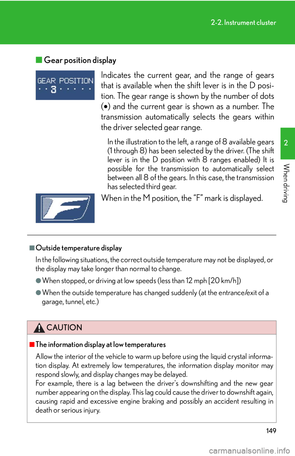
■Gear position display
Indicates the current gear, and the range of gears
that is available when the shift lever is in the D posi-
tion. The gear range is shown by the number of dots
() and the current gear is shown as a number. The
transmission automatically selects the gears within
the driver selected gear range.
In the illustration to the left, a range of 8 available gears
(1 through 8) has been selected by the driver. (The shift
lever is in the D position with 8 ranges enabled) It is
possible for the transmission to automatically select
between all 8 of the gears. In this case, the transmission
has selected third gear.
When in the M position, the “F” mark is displayed.
■Outside temperature display
In the following situations, the correct outside temperature may not be displayed, or
the display may take longer than normal to change.
●When stopped, or driving at low speeds (less than 12 mph [20 km/h])
●When the outside temperature has changed suddenly (at the entrance/exit of a
garage, tunnel, etc.)
CAUTION
■The information display at low temperatures
Allow the interior of the vehicle to warm up before using the liquid crystal informa-
tion display. At extremely low temperatures, the information display monitor may
respond slowly, and display changes may be delayed.
For example, there is a lag between the driver's downshifting and the new gear
number appearing on the display. This lag could cause the driver to downshift again,
causing rapid and excessive engine braking and possibly an accident resulting in
death or serious injury.
Page 161 of 543
161
2-4. Using other driving systems
2
When driving
Dynamic radar cruise control
Dynamic radar cruise control supplements conventional cruise control
with a vehicle-to-vehicle distance control. In vehicle-to-vehicle distance
control mode, the vehicle automatically accelerates or decelerates in
order to maintain a set following distance from vehicles ahead.
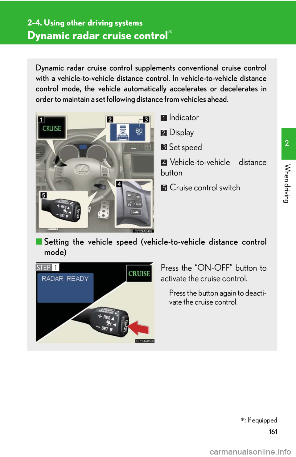
Indicator
Display
Set speed
Vehicle-to-vehicle distance
button
Cruise control switch
■Setting the vehicle speed (vehicle-to-vehicle distance control
mode)
Press the “ON-OFF” button to
activate the cruise control.
Press the button again to deacti-
vate the cruise control.
STEP1
�
: If equipped
Page 162 of 543
162
2-4. Using other driving systems
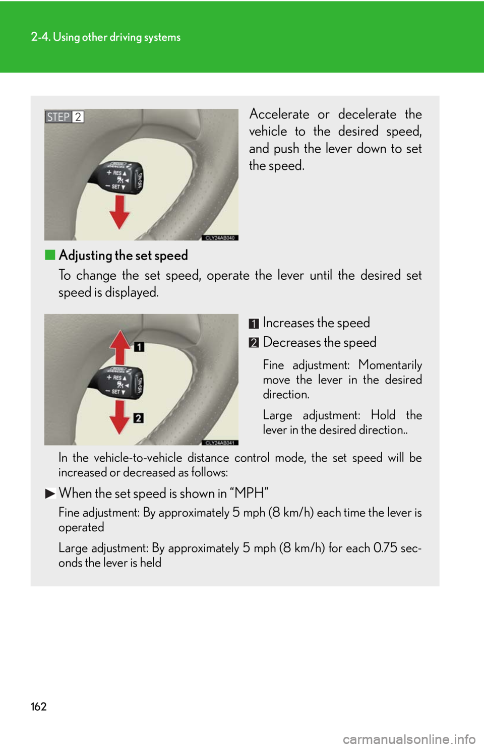
Accelerate or decelerate the
vehicle to the desired speed,
and push the lever down to set
the speed.
■Adjusting the set speed
To change the set speed, operate the lever until the desired set
speed is displayed.
Increases the speed
Decreases the speed
Fine adjustment: Momentarily
move the lever in the desired
direction.
Large adjustment: Hold the
lever in the desired direction..
In the vehicle-to-vehicle distance control mode, the set speed will be
increased or decreased as follows:
When the set speed is shown in “MPH”
Fine adjustment: By approximately 5 mph (8 km/h) each time the lever is
operated
Large adjustment: By approximately 5 mph (8 km/h) for each 0.75 sec-
onds the lever is held
STEP2
Page 163 of 543
163
2-4. Using other driving systems
2
When driving
When the set speed is shown in “km/h”
Fine adjustment: By approximately 3.1 mph (5 km/h) each time the lever is
operated
Large adjustment: By approximately 3.1 mph (5 km/h) for each 0.75 sec-
onds the lever is held
In the constant speed control mode (
P. 167), the set speed will be
increased or decreased as follows:
Fine adjustment: By approximately 1 mph (1.6 km/h) each time the lever is
operated
Large adjustment: The set speed can be increased or decreased continu-
ally until the lever is released.
■Changing the vehicle-to-vehicle distance
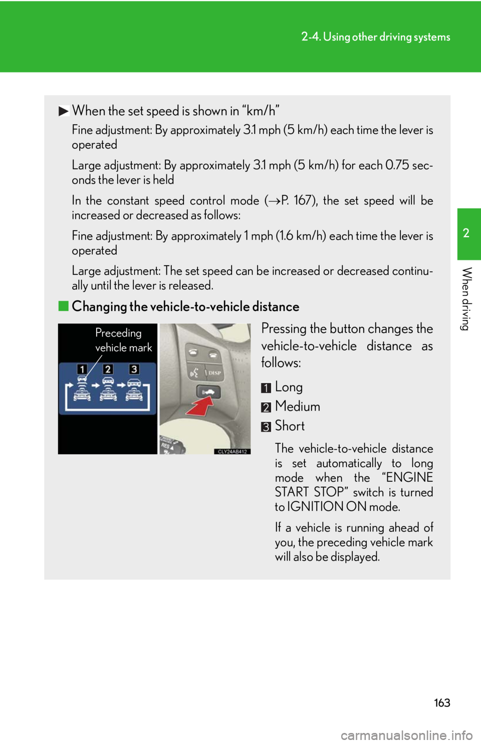
Pressing the button changes the
vehicle-to-vehicle distance as
follows:
Long
Medium
Short
The vehicle-to-vehicle distance
is set automatically to long
mode when the “ENGINE
START STOP” switch is turned
to IGNITION ON mode.
If a vehicle is running ahead of
you, the preceding vehicle mark
will also be displayed.
Preceding
vehicle mark
Page 166 of 543
166
2-4. Using other driving systems
Example of follow-up cruising
When following a vehicle driving slower than the set speed
The system continues follow-up cruising while adjusting for changes in the
speed of the vehicle ahead in order to maintain the vehicle-to-vehicle dis-
tance set by the driver.
Example of acceleration
When there are no longer any vehicles ahead driving slower than the
set speed
The system accelerates until the set speed is reached. The system then
returns to constant speed cruising.
Approach warning
When your vehicle is too close to a vehicle ahead, and sufficient auto-
matic deceleration via the cruise control is not possible, the display will
flash and the buzzer will sound to alert the driver. An example of this
would be if another driver cuts in front of you while you are following a
vehicle. Apply the brakes to ensure an appropriate vehicle-to-vehicle dis-
tance.
Page 174 of 543
174
2-4. Using other driving systems
Intuitive parking assist
: If equipped
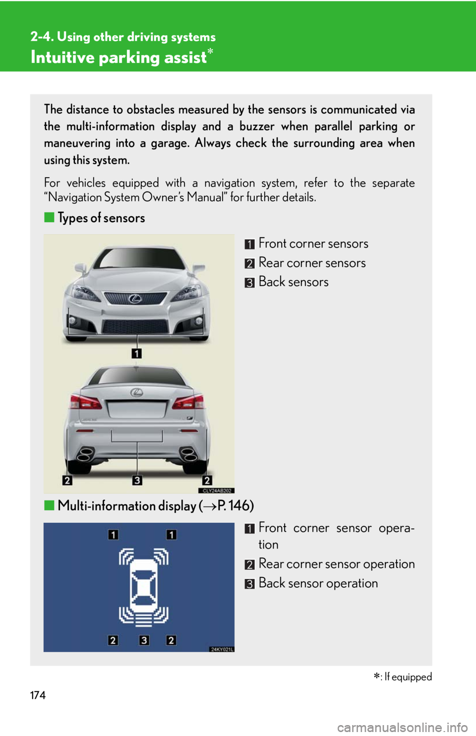
The distance to obstacles measured by the sensors is communicated via
the multi-information display and a buzzer when parallel parking or
maneuvering into a garage. Always check the surrounding area when
using this system.
For vehicles equipped with a navigation system, refer to the separate
“Navigation System Owner’s Manual” for further details.
■Types of sensors
Front corner sensors
Rear corner sensors
Back sensors
■Multi-information display (P. 146)
Front corner sensor opera-
tion
Rear corner sensor operation
Back sensor operation