REV Lexus IS250 2015 User Guide
[x] Cancel search | Manufacturer: LEXUS, Model Year: 2015, Model line: IS250, Model: Lexus IS250 2015Pages: 586, PDF Size: 8.66 MB
Page 73 of 586
721-2. Theft deterrent system
IS350/250_U (OM53C50U)
■System maintenance
The vehicle has a maintenance-free type alarm system.
■Items to check before locking the vehicle
To prevent unexpected triggering of the alarm and vehicle theft, make sure of the follow-
ing:
●Nobody is in the vehicle.
●The windows and moon roof are closed before the alarm is set.
●No valuables or other personal items are left in the vehicle.
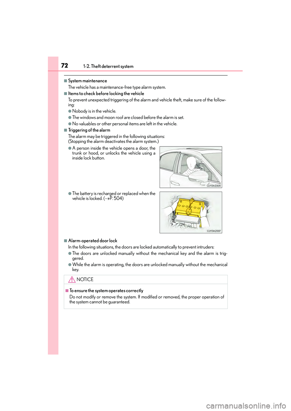
■Triggering of the alarm
The alarm may be triggered in the following situations:
(Stopping the alarm deactivates the alarm system.)
■Alarm-operated door lock
In the following situations, the doors are locked automatically to prevent intruders:
●The doors are unlocked manually without the mechanical key and the alarm is trig-
gered.
●While the alarm is operating, the doors are unlocked manually without the mechanical
key.
●A person inside the vehicle opens a door, the
trunk or hood, or unlocks the vehicle using a
inside lock button.
●The battery is recharged or replaced when the
vehicle is locked. (→P. 5 0 4 )
NOTICE
■To ensure the system operates correctly
Do not modify or remove the system. If modified or removed, the proper operation of
the system cannot be guaranteed.
Page 74 of 586
731-2. Theft deterrent system
1
For safety and security
IS350/250_U (OM53C50U)
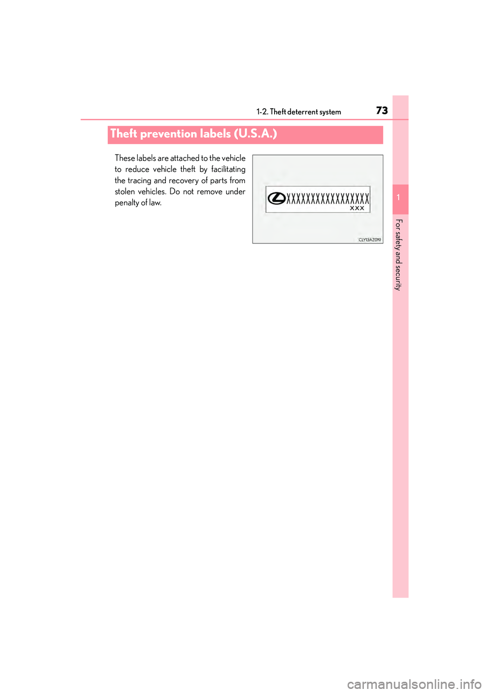
These labels are attached to the vehicle
to reduce vehicle theft by facilitating
the tracing and recovery of parts from
stolen vehicles. Do not remove under
penalty of law.
Theft prevention labels (U.S.A.)
Page 83 of 586
822. Instrument cluster
IS350/250_U (OM53C50U)
Engine coolant temperature gauge
Displays the engine coolant temperature
Ta c h o m e t e r
Displays the engine speed in revolutions per minute
Outside temperature
Displays the outside temperature within the range of -40°F (-40°C) to 122°F
(50°C). Low outside temperature indicator comes on when the ambient temperature
is 37°F (3°C) or lower.
Shift position and gear position ( → P. 1 6 4 )
Speedometer
Fuel gauge
Multi-information display
Presents the driver with a variety of vehicle data ( →P. 8 6 )
Displays warning messages in case of a malfunction ( →P. 4 7 2 )
Odometer and trip meter display
Odometer:
Displays the total distance the vehicle has been driven
Tr i p m e t e r :
Displays the distance the vehicle has been driven since the meter was last reset. Trip
meters “A” and “B” can be used to record and display different distances indepen-
dently.
1
2
3
4
5
6
7
8
Page 86 of 586
852. Instrument cluster
2
Instrument cluster
IS350/250_U (OM53C50U)
NOTICE
■To prevent damage to the engine and its components
●Do not let the indicator needle of the tachometer enter the red zone, which indicates
the maximum engine speed.
●The engine may be overheating if the engine coolant temperature gauge is in the red
zone (H). In this case, immediately stop the vehicle in a safe place, and check the
engine after it has cooled completely. (→P. 5 0 6 )
Page 88 of 586
872. Instrument cluster
2
Instrument cluster
IS350/250_U (OM53C50U)
◆Operating the meter control switches
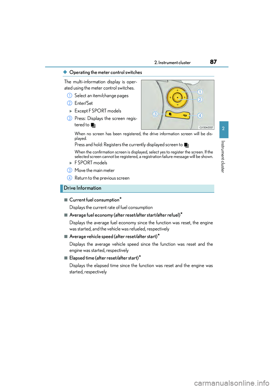
The multi-information display is oper-
ated using the meter control switches. Select an item/change pages
Enter/Set
�XExcept F SPORT models
Press: Displays the screen regis-
tered to
When no screen has been registered, the drive information screen will be dis-
played.
Press and hold: Registers the currently displayed screen to
When the confirmation screen is displayed, select yes to register the screen. If the
selected screen cannot be registered, a registration failure message will be shown.
�XF SPORT models
Move the main meter
Return to the previous screen
■Current fuel consumption*
Displays the current rate of fuel consumption
■Average fuel economy (after reset/after start/after refuel)*
Displays the average fuel economy since the function was reset, the engine
was started, and the vehicle was refueled, respectively
■Average vehicle speed (after reset/after start)*
Displays the average vehicle speed since the function was reset and the
engine was started, respectively
■Elapsed time (after reset/after start)*
Displays the elapsed time since the function was reset and the engine was
started, respectively
1
2
3
3
Drive Information
4
Page 90 of 586
892. Instrument cluster
2
Instrument cluster
IS350/250_U (OM53C50U)
■Pop-up display
Select to set the following pop-up displays, which may appear in some situa-
tions, on/off.
• Route guidance display of the navigation system-linked system (if equipped)
• Incoming call display of the hands-free phone system
• Windshield wiper switch operation display (if equipped)
• Headlight switch operation display (if equipped)
• Dynamic radar cruise control operation display (if equipped)
• Instrument panel brightness adjustment display
• Main meter switch operation display (F SPORT models)
■Accent color (except F SPORT models)
Select to change the accent colors on the screen, such as the cursor color.
■Needle (F SPORT models)
Select to change the needle color for the tachometer.
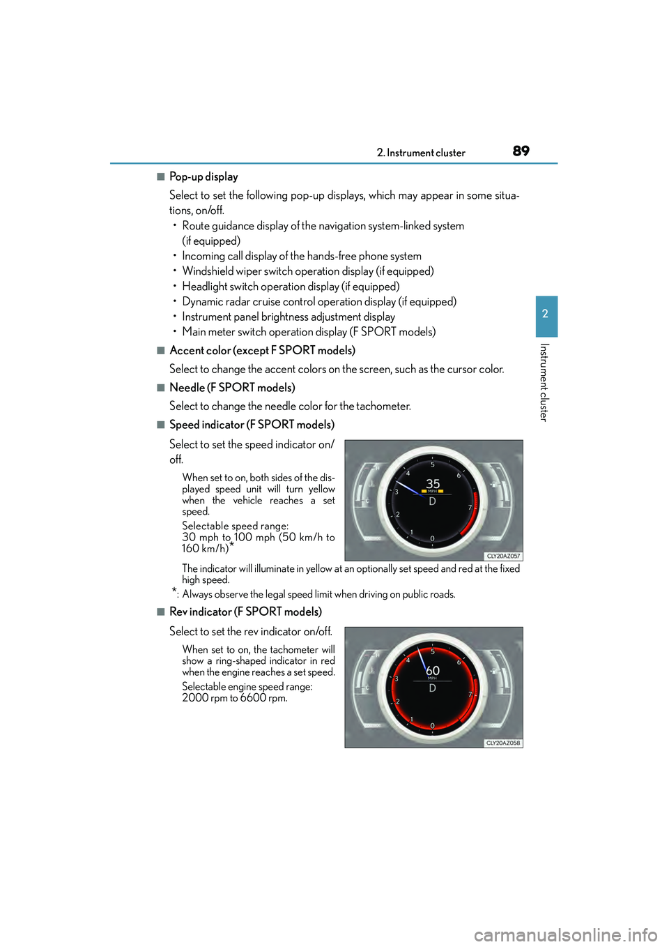
■Speed indicator (F SPORT models)
Select to set the speed indicator on/
off.
When set to on, both sides of the dis-
played speed unit will turn yellow
when the vehicle reaches a set
speed.
Selectable speed range:
30 mph to 100 mph (50 km/h to
160 km/h)
*
The indicator will illuminate in yellow at an optionally set speed and red at the fixed
high speed.
*: Always observe the legal speed limit when driving on public roads.
■Rev indicator (F SPORT models)
Select to set the rev indicator on/off.
When set to on, the tachometer will
show a ring-shaped indicator in red
when the engine reaches a set speed.
Selectable engine speed range:
2000 rpm to 6600 rpm.
Page 91 of 586
902. Instrument cluster
IS350/250_U (OM53C50U)
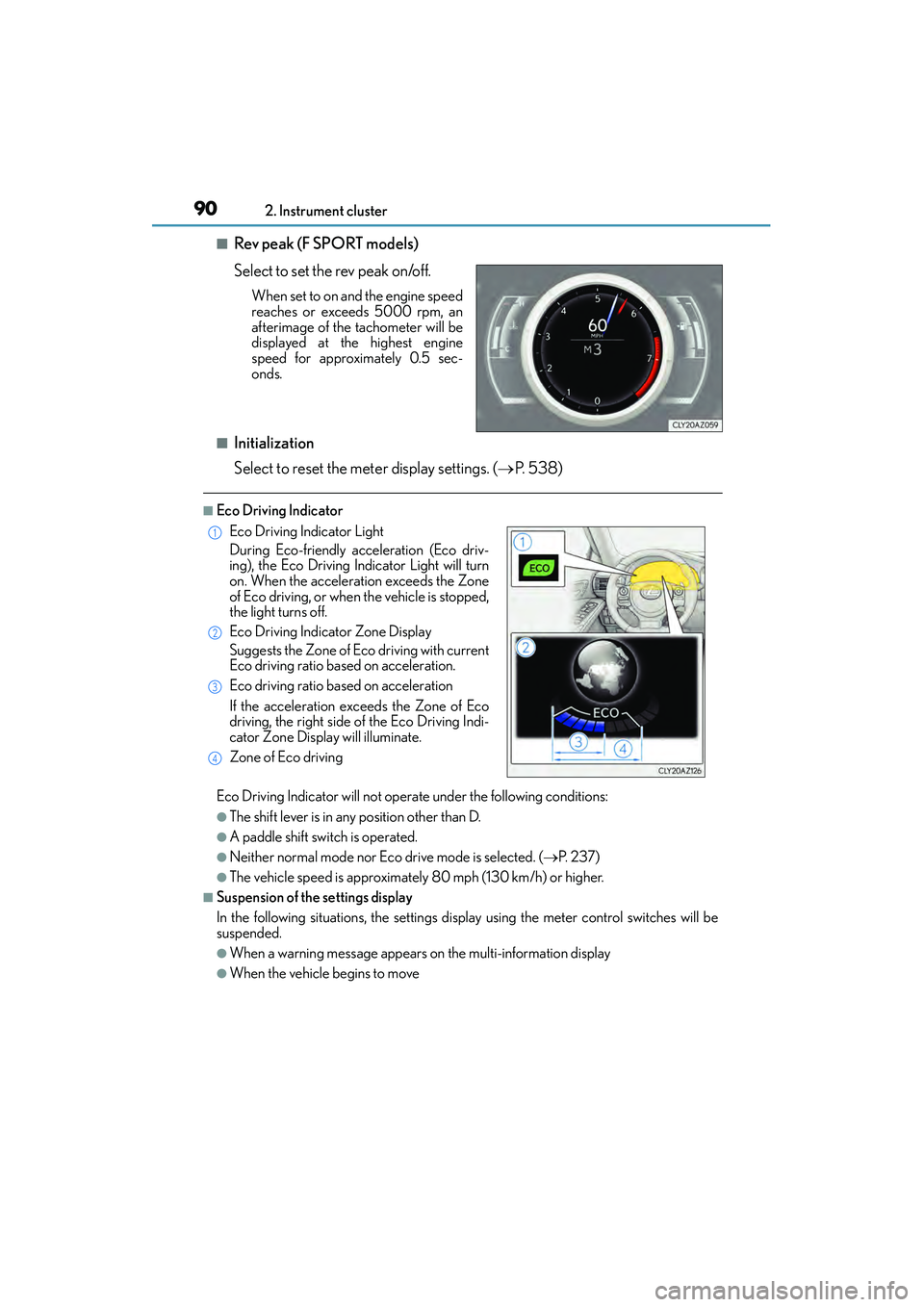
■Rev peak (F SPORT models)
Select to set the rev peak on/off.
When set to on and the engine speed
reaches or exceeds 5000 rpm, an
afterimage of the tachometer will be
displayed at the highest engine
speed for approximately 0.5 sec-
onds.
■Initialization
Select to reset the meter display settings. ( →P. 5 3 8 )
■Eco Driving Indicator
Eco Driving Indicator will not operate under the following conditions:
●The shift lever is in any position other than D.
●A paddle shift switch is operated.
●Neither normal mode nor Eco drive mode is selected. ( →P. 2 3 7 )
●The vehicle speed is approximately 80 mph (130 km/h) or higher.
■Suspension of the settings display
In the following situations, the settings display using the meter control switches will be
suspended.
●When a warning message appears on the multi-information display
●When the vehicle begins to move
Eco Driving Indicator Light
During Eco-friendly acceleration (Eco driv-
ing), the Eco Driving Indicator Light will turn
on. When the acceleration exceeds the Zone
of Eco driving, or when the vehicle is stopped,
the light turns off.
Eco Driving Indicator Zone Display
Suggests the Zone of Eco driving with current
Eco driving ratio based on acceleration.
Eco driving ratio based on acceleration
If the acceleration exceeds the Zone of Eco
driving, the right side of the Eco Driving Indi-
cator Zone Display will illuminate.
Zone of Eco driving1
2
3
4
Page 92 of 586

912. Instrument cluster
2
Instrument cluster
IS350/250_U (OM53C50U)
■Tire inflation pressure
●It may take a few minutes to display the tire inflation pressure after the engine switch is
turned to IGNITION ON mode. It may also take a few minutes to display the tire infla-
tion pressure after inflation pressure has been adjusted.
●“---” may be displayed if the tire information cannot be determined due to unfavorable
radio wave conditions.
●Tire inflation pressure changes with temperature. The displayed values may also be dif-
ferent from the values measured using a tire pressure gauge.
■Liquid crystal display
→P. 8 4
CAUTION
■The information display at low temperatures
Allow the interior of the vehicle to warm up before using the liquid crystal information
display. At extremely low temperatures, the information display monitor may respond
slowly, and display changes may be delayed.
For example, there is a lag between the driver’s shifting and the new gear number
appearing on the display. This lag could cause the driver to downshift again, causing
rapid and excessive engine braking and possibly an accident resulting in death or
injury.
■Cautions during setting up the display
As the engine needs to be running during setting up the display, ensure that the vehicle
is parked in a place with adequate ventilation. In a closed area such as a garage,
exhaust gases including harmful carbon monoxide (CO) may collect and enter the
vehicle. This may lead to death or a serious health hazard.
NOTICE
■During setting up the display
To prevent battery discharge, ensure that the engine is running while setting up the dis-
play features.
Page 96 of 586
952. Instrument cluster
2
Instrument cluster
IS350/250_U (OM53C50U)
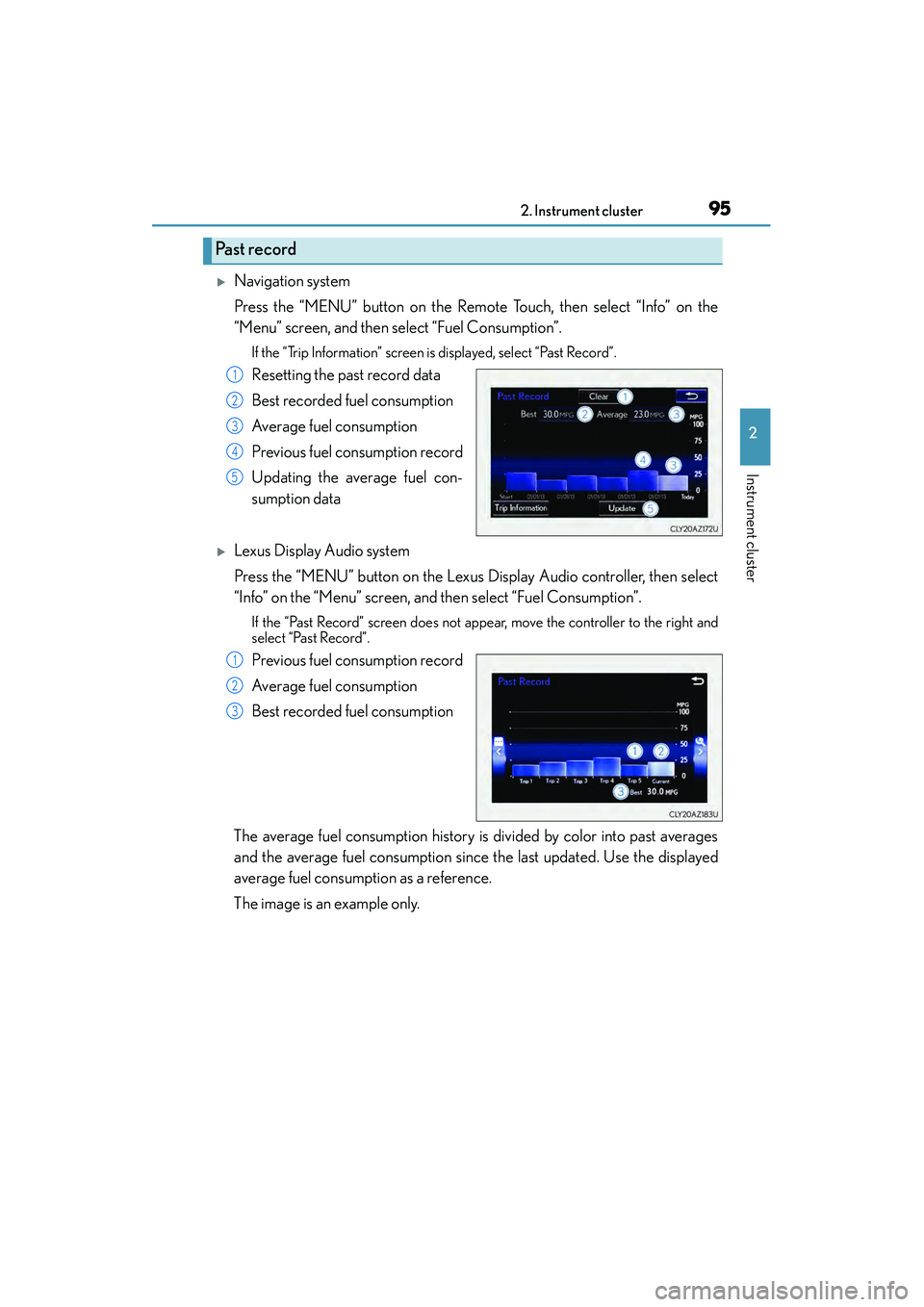
�XNavigation system
Press the “MENU” button on the Remote Touch, then select “Info” on the
“Menu” screen, and then select “Fuel Consumption”.
If the “Trip Information” screen is displayed, select “Past Record”.
Resetting the past record data
Best recorded fuel consumption
Average fuel consumption
Previous fuel consumption record
Updating the average fuel con-
sumption data
�XLexus Display Audio system
Press the “MENU” button on the Lexus Display Audio controller, then select
“Info” on the “Menu” screen, and then select “Fuel Consumption”.
If the “Past Record” screen does not appear, move the controller to the right and
select “Past Record”.
Previous fuel consumption record
Average fuel consumption
Best recorded fuel consumption
The average fuel consumption history is divided by color into past averages
and the average fuel consumption since the last updated. Use the displayed
average fuel consumption as a reference.
The image is an example only.
Past record
1
2
3
4
5
1
2
3
Page 103 of 586
1023-1. Key information
IS350/250_U (OM53C50U)
NOTICE
■To prevent key damage
●Do not drop the keys, subject them to strong shocks or bend them.
●Do not expose the keys to high temperatures for long periods of time.
●Do not get the keys wet or wash them in an ultrasonic washer etc.
●Do not attach metallic or magnetic materials to the keys or place the keys close to
such materials.
●Do not disassemble the keys.
●Do not attach a sticker or anything else to the surface of the electronic key.
●Do not place the keys near objects that produce magnetic fields, such as TVs, audio
systems and induction cookers, or medical electrical equipment, such as low-fre-
quency therapy equipment.
■Carrying the electronic key on your person
Carry the electronic key 3.9 in. (10 cm) or more away from electric appliances that are
turned on. Radio waves emitted from electric appliances within 3.9 in. (10 cm) of the
electronic key may interfere with the key, causing the key to not function properly.
■In case of a smart access system with push-button start malfunction or other key-
related problems
Take your vehicle with all the electronic keys provided with your vehicle, including the
card key, to your Lexus dealer.
■When an electronic key is lost
If the electronic key remains lost, the risk of vehicle theft increases significantly. Visit
your Lexus dealer immediately with all remaining electronic keys and the card key that
were provided with your vehicle.
■Handling the card key
●Do not apply excess force when inserting the mechanical key into the card key. Doing
so may damage the card key.
●If the battery or card key terminals get wet, the battery may corrode.
If the key is dropped into water, or if drin king water etc. is spilled on the key, immedi-
ately remove the battery cover and wipe the battery and terminals. (To remove the
battery cover, lightly grasp and pull it.) If the battery is corroded, have your Lexus
dealer replace the battery.
●Do not crush the battery cover or use a screwdriver to remove the battery cover.
Forcibly removing the battery cover may bend or damage the key.
●If the battery cover is frequently removed, the battery cover may become loose.
●When installing the battery, make sure to check the direction of the battery.
Installing the battery in the wrong direction may cause the battery to deplete rapidly.
●The surface of the card key may be damaged, or its coating may peel off in the follow-
ing situations:
• The card key is carried together with hard objects, such as coins and keys.
• The card key is scraped with a sharp object, such as the tip of a mechanical pencil.
• The surface of the card key is wiped with thinner or benzene.