instrument panel Lexus IS250C 2012 Instrument cluster / LEXUS 2012 IS250C,IS350C OWNERS MANUAL (OM53A62U)
[x] Cancel search | Manufacturer: LEXUS, Model Year: 2012, Model line: IS250C, Model: Lexus IS250C 2012Pages: 632, PDF Size: 6.77 MB
Page 14 of 632

14
Pictorial indexInstrument panel
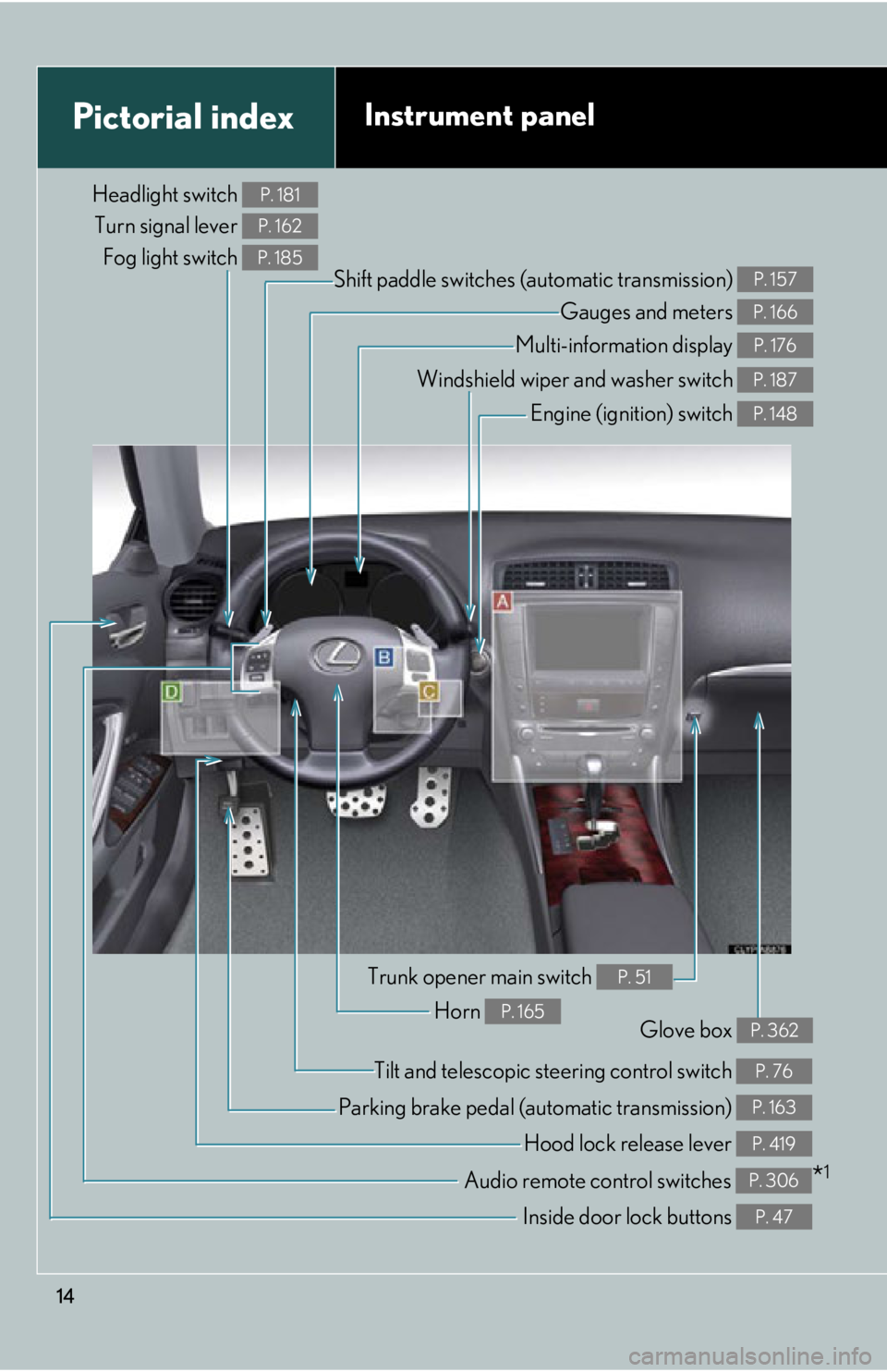
Headlight switch Turn signal lever Fog light switch P. 181
P. 162
P. 185
Shift paddle switches (automatic transmission) P. 157
Gauges and meters P. 166
Multi-information display P. 176
Windshield wiper and washer switch P. 187
Engine (ignition) switch P. 148
Trunk opener main switch P. 51
Tilt and telescopic steering control switch P. 76
Audio remote control switches *1P. 306
Horn P. 165Glove box P. 362
Parking brake pedal (automatic transmission) P. 163
Hood lock release lever P. 419
Inside door lock buttons P. 47
Page 16 of 632

16
Pictorial indexInstrument panel
A
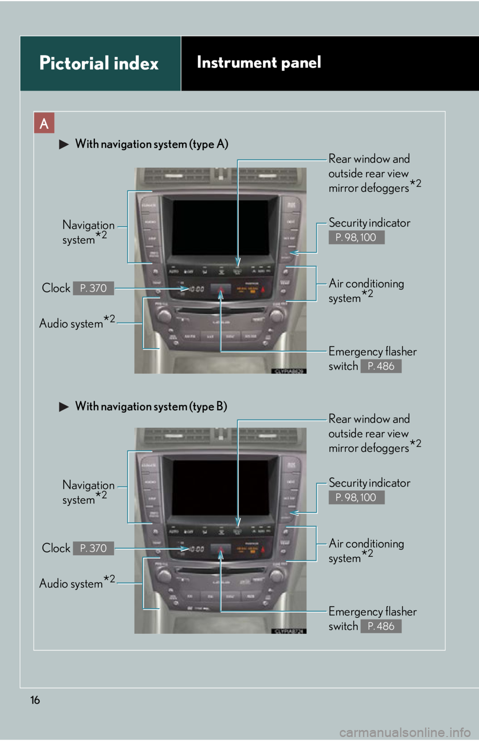
Navigation
system
*2
Clock P. 370
Audio system*2
Security indicator
P. 98, 100
Emergency flasher
switch
P. 486
Air conditioning
system
*2
With navigation system (type A)
Rear window and
outside rear view
mirror defoggers
*2
Navigation
system
*2
Clock P. 370
Audio system*2
Security indicator
P. 98, 100
Emergency flasher
switch
P. 486
Air conditioning
system
*2
With navigation system (type B)
Rear window and
outside rear view
mirror defoggers
*2
Page 18 of 632

18
Pictorial indexInstrument panel
D
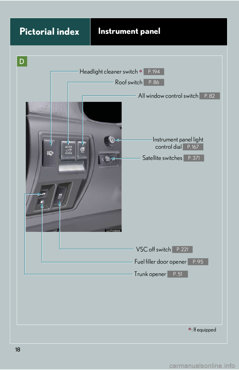
Headlight cleaner switch P. 194
Trunk opener P. 51
Fuel filler door opener P. 95
Roof switch P. 86
Satellite switches P. 371
Instrument panel lightcontrol dial
P. 167
: If equipped
All window control switch P. 82
VSC off switch P. 221
Page 39 of 632

39
1-2. Opening, closing and locking the doors and trunk
1
Before driving
■To operate the system properly
●Make sure to carry the electronic key when operating the system. Actions such
as locking and unlocking the doors cannot be performed from outside the vehi-
cle if the electronic key is inside the vehicle, even when the retractable hardtop
is open.
●Do not get the electronic key too close to the vehicle when operating the sys-
tem from the outside of the vehicle.
●Depending on the position and holding co ndition of the electronic key, the key
may not be detected correctly and the system may not operate properly. (The
alarm may go off accidentally, or the door lock prevention may not function.)
■Note for the entry function
●Even when the electronic key is within the effective range (detection areas), the
system may not operate properly in the following cases.
• The electronic key is too close to the window or outside door handle, near the
ground, or in a high place when the doors are locked or unlocked.
• The electronic key is near the ground or in a high place, or too close to the rear bumper center when the trunk is unlocked.
• The electronic key is on the instrument panel, rear package tray or floor, or in the glove box when the engine is started or “ENGINE START STOP” switch
modes are changed.
●Do not leave the electronic key on top of the instrument panel or near the door
pockets when exiting the vehicle. Depending on the radio wave reception con-
ditions, it may be detected by the an tenna outside the cabin and the door will
become lockable from the outside, possibly trapping the electronic key inside
the vehicle.
●As long as the electronic key is within the effective range, the doors may be
locked or unlocked by anyone.
●Even if the electronic key is not inside th e vehicle, it may be possible to start the
engine if the electronic key is near the window.
●The doors may unlock if a large amount of water splashes on the door handle,
such as in the rain or in a car wash. (The doors will automatically be locked after
approximately 60 seconds if the doors are not opened and closed.)
●Gripping the door handle when wearing a glove may not unlock the door.
Page 113 of 632

113
1-7. Safety information
1
Before driving
CAUTION
■SRS airbag precautions
Observe the following precautions regarding the airbags.
Failure to do so may cause death or serious injury.
●The driver and all passengers in the vehicle must wear their seat belts properly.
The SRS airbags are supplemental devices to be used with the seat belts.
●The SRS driver airbag deploys with considerable force, and can cause death or
serious injury especially if the driver is very close to the airbag. The National
Highway Traffic Safety Administration (“NHTSA”) advises:
Since the risk zone for driver airbag is th e first 2 - 3 in. (50 - 75 mm) of inflation,
placing yourself 10 in. (250 mm) from your driver airbag provides you with a
clear margin of safety. This distance is measured from the center of the steering
wheel to your breastbone. If you sit less than 10 in. (250 mm) away now, you can
change your driving position in several ways:
• Move your seat to the rear as far as you can while still reaching the pedals
comfortably.
• Slightly recline the back of the seat. Although vehicle designs vary, many dr ivers can achieve the 10 in. (250 mm)
distance, even with the driver seat all the way forward, simply by reclining the
back of the seat somewhat. If reclining the back of your seat makes it hard to
see the road, raise yourself by using a firm, non-slippery cushion, or raise the
seat if your vehicle has that feature.
• If your steering wheel is adjustable, ti lt it downward. This points the airbag
toward your chest instead of your head and neck.
The seat should be adjusted as recommended by NHTSA above, while still main-
taining control of the foot pedals, steering wheel, and your view of the instrument
panel controls.
Page 116 of 632

116
1-7. Safety information
CAUTION
■SRS airbag precautions
●If the vinyl cover is put on the area where the SRS knee airbag will deploy, be sure
to remove it.
●Do not use seat accessories which cover the parts where the SRS side airbags
inflate as they may interfere with inflation of the airbags.
●Do not strike or apply significant levels of force to the area of the SRS airbag
components shown on P. 107.
Doing so can cause the SRS airbags to malfunction.
●Do not touch any of the component parts immediately after the SRS airbags have
deployed (inflated) as they may be hot.
●If breathing becomes difficult after the SRS airbag has deployed, open a door or
window to allow fresh air in, or leave the vehicle if it is safe to do so. Wash off any
residue as soon as possible to prevent skin irritation.
●If the areas where the SRS airbags are stored, such as the steering wheel pad, are
damaged or cracked, have them replaced by your Lexus dealer.
●Do not attach anything to or lean anything
against areas such as the dashboard, steer-
ing wheel pad and lower portion of the
instrument panel.
These items can become projectiles when
SRS driver, front passenger and knee air-
bags deploy.
●Do not attach anything to areas such as the
door.
Page 117 of 632

117
1-7. Safety information
1
Before driving
CAUTION
■Modification and disposal of SRS airbag system components
Do not dispose of your vehicle or perform any of the following modifications with-
out consulting your Lexus dealer.
The SRS airbag may malfunct ion or deploy (inflate) accidentally, causing death or
serious injury.
●Installation, removal, disassembly and repair of the SRS airbags
●Repairs, modifications, removal or replace ment of the steering wheel, instrument
panel, dashboard, seats or seat upholstery
●Repairs or modifications of the front fend er, front bumper, or side of the occupant
compartment
●Installation of snow plows, winches, etc. to the front grille (bull bars, kangaroo bar
etc.)
●Modifications to the vehi cle's suspension system
●Installation of electronic devices such as mobile two-way radios or CD players
●Modifications to your vehicle for a person with a physical disability
Page 167 of 632

167
2-2. Instrument cluster
2
When driving
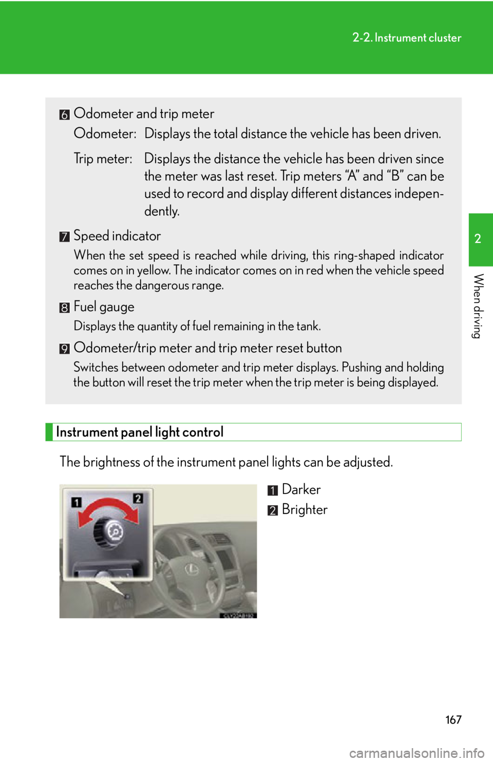
Instrument panel light controlThe brightness of the instrument panel lights can be adjusted. Darker
Brighter
Odometer and trip meter
Odometer: Displays the total distance the vehicle has been driven.
Trip meter: Displays the distance the vehicle has been driven since
the meter was last reset. Trip meters “A” and “B” can be
used to record and display different distances indepen-
dently.
Speed indicator
When the set speed is reached while driving, this ring-shaped indicator
comes on in yellow. The indicator comes on in red when the vehicle speed
reaches the dangerous range.
Fuel gauge
Displays the quantity of fuel remaining in the tank.
Odometer/trip meter and trip meter reset button
Switches between odometer and trip meter displays. Pushing and holding
the button will reset the trip meter when the trip meter is being displayed.
Page 171 of 632

171
2-2. Instrument cluster
2
When driving
■Speed indicator display conditions and vehicle speed setting range
Vehicle speed setting range: Approximately 30 to 100 mph (approximately 50 to 160 km/h)
When the maximum speed is selected, the speed indicator comes on only in red.
■Tacho indicator display conditions and engine speed setting range
Engine rpm setting range: Approximately 2000 to 6500 rpm (r/min)
When the maximum rpm is selected, the tacho indicator comes on only in red.
■The brightness of the instrument panel lights
When the headlight switch is turned to on, the brightness will be reduced slightly
unless the control dial is turned fully clockwise.
NOTICE
■To prevent damage to the engine and its components
●Do not let the indicator needle of the tachometer enter the red zone, which indi-
cates the maximum engine speed.
●The engine may be overheating if the temperature gauge is in the red zone (H). In
this case, immediately stop the vehicle in a safe place, and check the engine after
it has cooled completely. ( P. 5 4 2 )
Page 172 of 632

172
2-2. Instrument cluster
Indicators and warning lights
The indicator and warning lights on the instrument cluster and center
panel inform the driver of the status of the vehicle’s various systems.
Instrument cluster
The units used on the speedometer and the tachometer gauge display may
differ depending on the model/type.
Center panel