clock LEXUS IS350 2022 Owners Manual
[x] Cancel search | Manufacturer: LEXUS, Model Year: 2022, Model line: IS350, Model: LEXUS IS350 2022Pages: 440, PDF Size: 22.72 MB
Page 71 of 440

692-1. Instrument cluster
2
Vehicle status information and indicators
■Locations of gauges and meters (except F SPORT models)
The units of measure may differ depending on the intended destination of the vehicle.
Engine coolant temperature gauge
Displays the engine coolant temperature
Tachometer
Displays the engine speed in revolutions per minute
Outside temperature
Displays the outside temperature within the range of -40°F (-40°C) to 122°F (50°C)
Multi-information display
Presents the driver with a variety of vehicle data ( P.75)
Displays warning messages if a malfunction occurs (P.338)
Clock
Time displayed is linked to the anal og clock on the center panel. (P.260)
Speedometer
Fuel gauge
Displays the quantity of fuel remaining in the tank
Shift position and gear position ( P.134)
Odometer and trip meter display ( P.74)
Gauges and meters
Meter display
A
B
C
D
E
F
G
H
I
Page 72 of 440

702-1. Instrument cluster
■Locations of gauges and meters (F SPORT models)
Main meter in center position (IS350 AWD/IS350/IS300 AWD/IS300)
The units of measure may differ depending on the intended destination of the vehicle.
Engine coolant temperature gauge
Displays the engine coolant temperature
Outside temperature
Displays the outside temperature within t he range of -40°F (-40°C) to 122°F (50°C)
Tachometer
Displays the engine speed in revolutions per minute
When sport mode is selected for the driving mode, the periphery of the tachometer will
change color and the scale of the tachometer will be emphasized.
Speedometer
Shift position and gear position ( P.134)
Multi-information display
Presents the driver with a variety of vehicle data ( P.75)
Displays warning messages if a malfunction occurs (P.338)
Clock
Time displayed is linked to the anal og clock on the center panel. (P.260)
Fuel gauge
Displays the quantity of fuel remaining in the tank
Odometer and trip meter display ( P.74)
A
B
C
D
E
F
G
H
I
Page 73 of 440

712-1. Instrument cluster
2
Vehicle status information and indicators
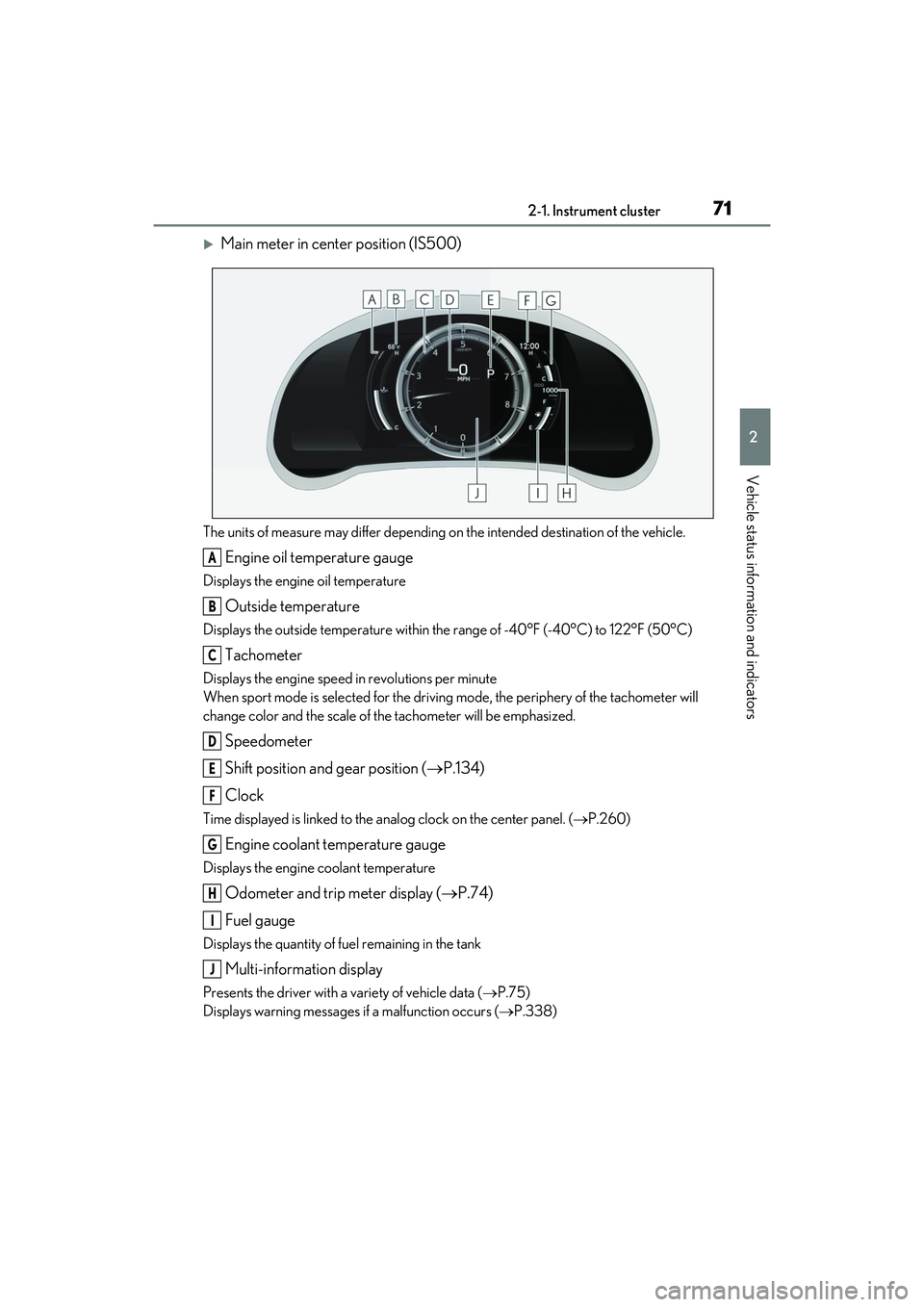
Main meter in center position (IS500)
The units of measure may differ depending on the intended destination of the vehicle.
Engine oil temperature gauge
Displays the engine oil temperature
Outside temperature
Displays the outside temperature within the range of -40°F (-40°C) to 122°F (50°C)
Tachometer
Displays the engine speed in revolutions per minute
When sport mode is selected for the driving mode, the periphery of the tachometer will
change color and the scale of the tachometer will be emphasized.
Speedometer
Shift position and gear position ( P.134)
Clock
Time displayed is linked to the anal og clock on the center panel. (P.260)
Engine coolant temperature gauge
Displays the engine coolant temperature
Odometer and trip meter display ( P.74)
Fuel gauge
Displays the quantity of fuel remaining in the tank
Multi-information display
Presents the driver with a variety of vehicle data ( P.75)
Displays warning messages if a malfunction occurs (P.338)
A
B
C
D
E
F
G
H
I
J
Page 74 of 440

722-1. Instrument cluster
Main meter moved to the right
The units of measure may differ depending on the intended destination of the vehicle.
Outside temperature
Displays the outside temperature within the range of -40°F (-40°C) to 122°F (50°C)
Clock
Time displayed is linked to the analog clock on the center panel. (P.260)
Tachometer
Displays the engine speed in revolutions per minute
When sport mode is selected for the driving mode, the periphery of the tachometer will
change color and the scale of the tachometer will be emphasized.
Speedometer
Shift position and gear position ( P.134)
Odometer and trip meter display ( P.74)
Multi-information display
Presents the driver with a variety of vehicle data ( P.75)
Displays warning messages if a malfunction occurs (P.338)
Engine coolant temperature gauge
Displays the engine coolant temperature
Fuel gauge
Displays the quantity of fuel remaining in the tank
■Rev indicator (F SPORT models)
When the engine speed reaches a set
speed, a ring-shaped indicator will be
displayed on the tachometer.
A
B
C
D
E
F
G
H
I
Page 83 of 440

812-1. Instrument cluster
2
Vehicle status information and indicators
■Meter display settings that can be
changed
Language
Select to change th e language displayed.
Units
Select to change the units of measure dis-
played.
Speedometer display (except F
SPORT models)
Select to set the disp lay of the speedome-
ter to digital/analog/both digital and ana-
log.
Drive information 1/Drive informa-
tion 2/Drive information 3
Select to select up to 2 items ( P.78) that
will be displayed on ea ch Drive information
screen (Drive information 1 screen, Drive
information 2 screen and Drive informa-
tion 3 screen) respectively.
Clock
Select to switch be tween 12-hour display
and 24-hour display.
Pop-up display
Select to enable/disab le pop-up displays
for each relevant system.
Accent color
Select to change the accent color on the
screen, such as the cursor color.
Rev indicator (F SPORT models)
• Select to enable/disable the rev indica-
tor.
• Select to set the engine speed at which the rev indicator (amber) will begin to be
displayed.
Rev peak (F SPORT models)
Select to enable/disable the rev peak.
Eco Driving Indicator Light
Select to enable/dis able the Eco Driving
Indicator Light.
Default setting
Select to reset the meter display settings to
the default setting.
■Vehicle functions and settings that
can be changed
P.388
■Suspension of the settings display
●Some settings cannot be changed while
driving. When changing settings, park
the vehicle in a safe place.
●If a warning message is displayed, opera-
tion of the settings display will be sus-
pended.
Settings display
WARNING
■Cautions during setting up the dis-
play
As the engine needs to be running
during setting up the display, en sure that
the vehicle is parked in a place with ade-
quate ventilation. In a closed area such as
a garage, exhaust gases including harm-
ful carbon monoxide (CO) may collect
and enter the vehicle. This may lead to
death or a serious health hazard.
NOTICE
■During setting up the display
To prevent battery discharge, ensure that
the engine is running while setting up the
display features.
Page 262 of 440

2605-5. Using the other interior features
5-5.Using the other interior features
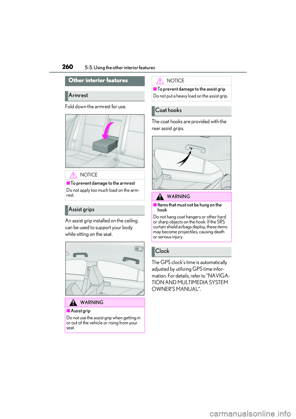
Fold down the armrest for use.
An assist grip installed on the ceiling
can be used to support your body
while sitting on the seat.The coat hooks are provided with the
rear assist grips.
The GPS clock’s time is automatically
adjusted by utilizing GPS time infor-
mation. For details, refer to “NAVIGA-
TION AND MULTIMEDIA SYSTEM
OWNER’S MANUAL”.
Other interior features
Armrest
NOTICE
■To prevent damage to the armrest
Do not apply too much load on the arm-
rest.
Assist grips
WARNING
■Assist grip
Do not use the assist grip when getting in
or out of the vehicle or rising from your
seat.
NOTICE
■To prevent damage to the assist grip
Do not put a heavy load on the assist grip.
Coat hooks
WARNING
■Items that must not be hung on the
hook
Do not hang coat hangers or other hard
or sharp objects on the hook. If the SRS
curtain shield airbags deploy, these items
may become projectiles, causing death
or serious injury.
Clock
Page 293 of 440

2916-3. Do-it-yourself maintenance
6
Maintenance and care
IS300
IS500
1 Remove the oil filler cap by turning
it counterclockwise.
2 Add engine oil slowly, checking the
dipstick.
3 Install the oil filler cap by turning it
clockwise.
■Checking the oil type and prepar-
ing the item needed
Make sure to check the oil type and
prepare the items needed before add-
ing oil.
Engine oil selection
P.367
Oil quantity (Low Full)
1.6 qt. (1.5 L, 1.3 Imp. qt.)
Item
Clean funnel
■Engine oil consumption
A certain amount of engine oil will be con-
sumed while driving. In the following situa-
tions, oil consumption may increase, and
engine oil may need to be refilled in
between oil maintenance intervals.
●When the engine is new, for example
directly after purchasing the vehicle or
after replacing the engine
●If low quality oil or oil of an inappropriate
viscosity is used
●When driving at high engine speeds or
with a heavy load, or when driving while
accelerating or dece lerating frequently
●When leaving the engine idling for a long
time, or when driving frequently through
heavy traffic
■After changing the engine oil (IS350
AWD/IS350/IS300 AWD/IS300)
The engine oil maintenance data should be
reset. Perform the following procedures:
1 Press or of the meter control
switch to select on the multi-infor-
mation display.
2 Press or of the meter control
switch, select the “Vehicle Settings”
then “Oil Maintenance”. (To confirm
setting, press .)
3 Select the “Yes” and press .
4 A message will be displayed on the
multi-information display when the
reset procedure has been completed.
WARNING
■Used engine oil
●Used engine oil contains potentially
harmful contaminants which may
cause skin disorders such as inflamma-
tion and skin cancer, so care should be
taken to avoid prolonged and
repeated contact. To remove used
engine oil from your skin, wash thor-
oughly with soap and water.
Page 317 of 440

3156-3. Do-it-yourself maintenance
6
Maintenance and care
■Front turn signal lights (bulb type)
1 IS500: Removing the engine com-
partment cover.
1 Push the center of the clip.
2 Remove the clip.
2 For the left side only: Pinch the clip
to remove the washer fluid filler
opening. 3
Turn the bulb base
counterclockwise.
4 Remove the light bulb.
5 Install a new light bulb then install
the bulb base to the light unit by
inserting it and turning the bulb
base clockwise.
After installing the light bulb, turn on the
front turn signal light to visually check that
there is no light leaking from the bulb base.
6 After replacing the left side bulb,
install the washer fluid filler opening
to its original position.
Replacing light bulbs
Page 319 of 440

3176-3. Do-it-yourself maintenance
6
Maintenance and care
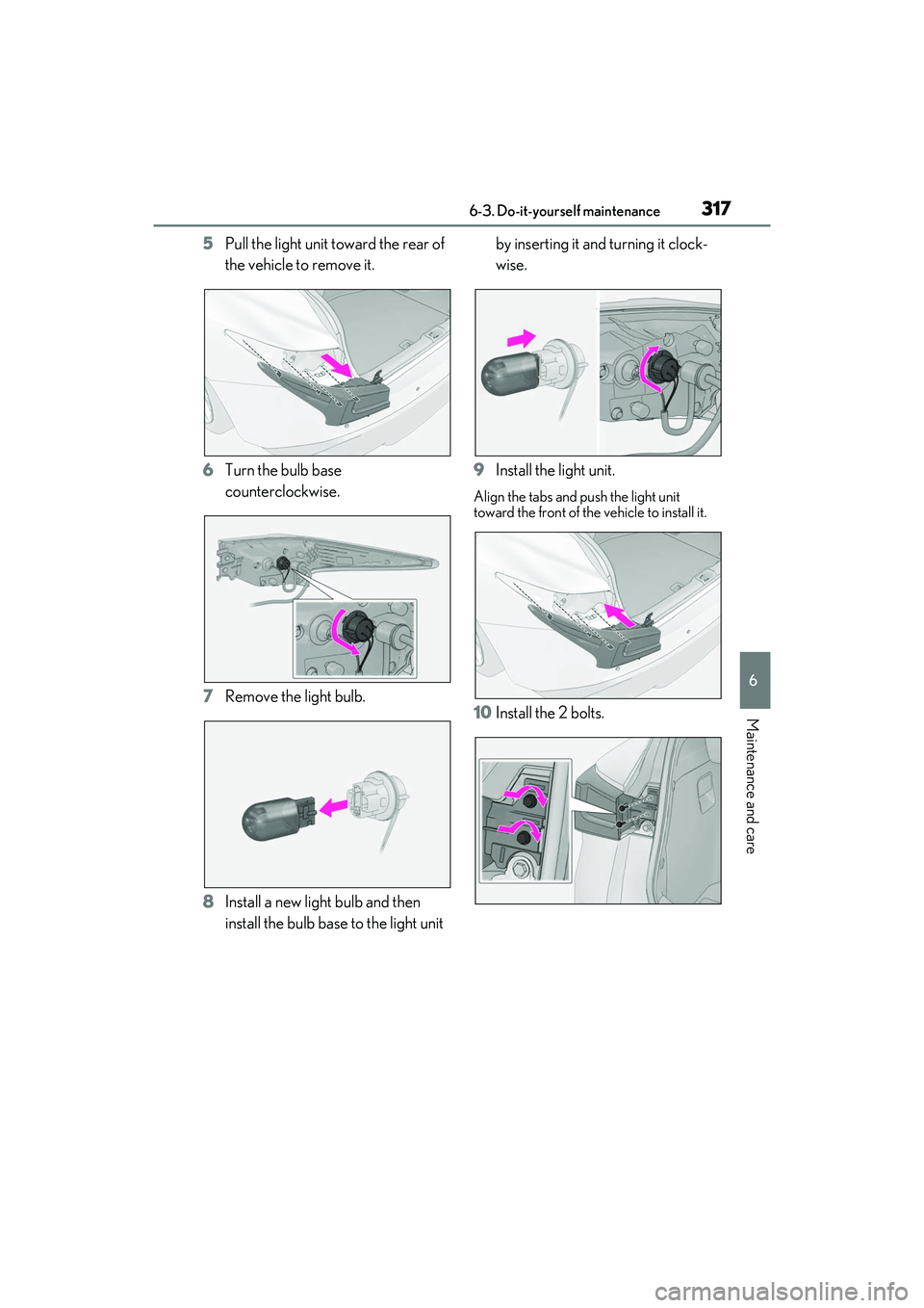
5Pull the light unit toward the rear of
the vehicle to remove it.
6 Turn the bulb base
counterclockwise.
7 Remove the light bulb.
8 Install a new light bulb and then
install the bulb base to the light unit by inserting it and turning it clock-
wise.
9 Install the light unit.
Align the tabs and push the light unit
toward the front of the vehicle to install it.
10Install the 2 bolts.
Page 347 of 440

3457-2. Steps to take in an emergency
7
When trouble arises
Turn the guide pin clockwise to tighten it
until it stops.
6Remove all the wheel bolts and the
tire.
When resting the tire on the ground, place
the tire so that the wheel design faces up to
avoid scratching the wheel surface.
1Remove any dirt or foreign matter
from the wheel contact surfaces
and wheel bolts.
If foreign matter is on the wheel contact
surface, the wheel bolt s may loosen while the vehicle is in motion, causing the tire to
come off.
2
Align a wheel bolt hole on the spare
tire with the guide pin, and set the
spare tire on the guide pin.
Securely set the spare tire so that its wheel
is touching the contact surface.
3Loosely tighten each wheel bolt by
hand or using a wheel bolt socket
.
Push the spare tire to prevent it from falling.
Do not use the wheel bolt socket for any-
thing other than loosely tightening the
wheel bolts by hand.
WARNING
■Replacing a flat tire
Do not touch the disc wheels or the area
around the brakes immediately after the
vehicle has been driven. After the vehicle
has been driven the disc wheels and the
area around the brakes will be extremely
hot. Touching these areas with hands,
feet or other body parts while changing a
tire, etc. may result in burns.
Installing the spare tire
A