fuel LEXUS LS430 2003 Factory User Guide
[x] Cancel search | Manufacturer: LEXUS, Model Year: 2003, Model line: LS430, Model: LEXUS LS430 2003Pages: 4500, PDF Size: 87.45 MB
Page 1801 of 4500

Fig. 58: Identifying Fuel Sender Gauge Connector Terminals
Courtesy of TOYOTA MOTOR SALES, U.S.A., INC.
Page 1802 of 4500

Fig. 59: Identifying Float Position
Courtesy of TOYOTA MOTOR SALES, U.S.A., INC.
OK: GO TO NEXT STEP
5.CHECK HARNESS AND CONNECTOR (FUEL SENDER GAUGE ASSY - LUGGAGE ROOM
JUNCTION BLOCK ASSY) (SEE HOW TO PROCEED WITH TROUBLESHOOTING
)
a. Disconnect the F19, L13 and L14 connectors.
b. Measure the resistance according to the value (s) in the table below.
Standard
RESISTANCE SPECIFICATIONS
Tester ConnectionConditionSpecified Condition
L14-6 - F19-1AlwaysBelow 1 ohms
L14-4 - F19-2AlwaysBelow 1 ohms
L13-10 - F19-3AlwaysBelow 1 ohms
Page 1805 of 4500

Fig. 60: Identifying Fuel Sender Gauge Assy And Luggage Room Junction Block Assy Connector
Terminals
Courtesy of TOYOTA MOTOR SALES, U.S.A., INC.
NG: REPAIR OR REPLACE HARNESS OR CONNECTOR
OK: GO TO NEXT STEP
6.INSPECT FUEL SENDER GAUGE ASSY (SUB)
a. Measure the voltage according to the value (s) in the table below.
Standard
VOLTAGE SPECIFICATIONS
b. Remove the fuel sender gauge assy.
c. Connect the fuel sender gauge connector.
d. Check that the float position is between E and F.
e. Measure the voltage between the terminals 2 and 1 of connector according to the value (s) in the
table below.
Standard
VOLTAGE SPECIFICATIONS
Tester ConnectionConditionSpecified Condition
F20-1 - F20-3Ignition switch ACC or ONBelow 1 to 5 V
Float levelFloat position mm (in.)Voltage (V)
F1.4(0.06) +/- 3(0.12)4.5 to 4.75
1/2190.2(7.49) +/- 3(0.12)0.45 +/- 0.65
Warning195.7(7.70) +/- 3(0.12)0.20 to 0.45
Page 1807 of 4500

Fig. 62: Identifying Float Position
Courtesy of TOYOTA MOTOR SALES, U.S.A., INC.
NG: REPLACE FUEL SENDER GAUGE ASSY (SUB)
OK: GO TO NEXT STEP
7.CHECK HARNESS AND CONNECTOR (FUEL SENDER GAUGE ASSY - LUGGAGE ROOM
JUNCTION BLOCK ASSY) (SEE HOW TO PROCEED WITH TROUBLESHOOTING
)
a. Disconnect the F20, L13 and 14 connectors.
b. Measure the resistance according to the value (s) in the table below.
Standard
RESISTANCE SPECIFICATIONS
Tester ConnectionConditionSpecified Condition
L14-7 - F19-1AlwaysBelow 1 ohms
L13-9 - F19-2AlwaysBelow 1 ohms
L14-15 - F19-3AlwaysBelow 1 ohms
Page 1810 of 4500
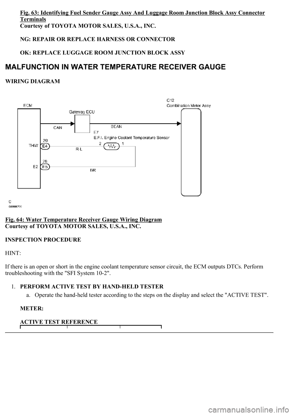
Fig. 63: Identifying Fuel Sender Gauge Assy And Luggage Room Junction Block Assy Connector
Terminals
Courtesy of TOYOTA MOTOR SALES, U.S.A., INC.
NG: REPAIR OR REPLACE HARNESS OR CONNECTOR
OK: REPLACE LUGGAGE ROOM JUNCTION BLOCK ASSY
WIRING DIAGRAM
Fig. 64: Water Temperature Receiver Gauge Wiring Diagram
Courtesy of TOYOTA MOTOR SALES, U.S.A., INC.
INSPECTION PROCEDURE
HINT:
If there is an open or short in the engine coolant temperature sensor circuit, the ECM outputs DTCs. Perform
troubleshooting with the "SFI System 10-2".
1.PERFORM ACTIVE TEST BY HAND-HELD TESTER
a. Operate the hand-held tester according to the steps on the display and select the "ACTIVE TEST".
METER:
ACTIVE TEST REFERENCE
Page 1845 of 4500

c. Compare the result of the test with the standard indication.
DC 13.5 V, 25°C (77°F)
Fig. 89: Tachometer Acceptable Reference Chart
Courtesy of TOYOTA MOTOR SALES, U.S.A., INC.
4.INSPECT FUEL RECEIVER GAUGE
a. Disconnect the connector from the sender gauge.
b. Connect terminals 1 and 2 on the wire harness side connector of the fuel sender gauge.
c. Turn the ignition switch to the ON position, then check the position of the receiver gauge needle.
OK:
Needle position is on (EMPTY).
d. Connect terminals 2 and 3 on the wire harness side connector of the fuel sender gauge.
e. Turn the i
gnition switch to the ON position, then check the position of the receiver gauge needle.
Page 1846 of 4500

Fig. 90: Identifying Fuel Sender Gauge Connector Terminals
Courtesy of TOYOTA MOTOR SALES, U.S.A., INC.
OK:
Needle position is on (FULL).
5.INSPECT FUEL LEVEL WARNING
a. Disconnect the connector from the sender gauge.
b. Turn the ignition switch to the ON position, then check that the fuel level needle indicates EMPTY
and the fuel level warning light comes on.
OK:
Fuel level warning light comes on.
Page 2016 of 4500

AUDI
AUDI - IMPORTED CARS & TRUCKS
SLXBehind Lower Left Corner Of Dash, Behind
Cover
Vigor
1992-93Under Right Side Of Dash, Near Center
Console
1994Behind Glove Compartment
2.2CL & 2.3CLIn Front Of Shift Lever, Behind Ashtray
2.5TLIn Front Of Shift Lever, Behind Ashtray
3.0CLIn Front Of Shift Lever, Behind Ashtray
3.2TL & 3.5RLIn Front Of Shift Lever, Behind Ashtray
ApplicationConnector Location
A4
1996Next To Rear Ashtray
1997-01 (1.8L Turbo)Behind Cover, Under Left Side Of Steering
Column
1997-99 (2.8L V6)Under Cover, Next To Rear Ashtray
1997-Under Left Side Of Dash, Behind Cover
A6
1995Under Ashtray, In Front Storage
Compartment Of Center Console
1996-97Under Cover, Next To Parking Brake
Handle
Cabriolet
1994-96In Fuse/Relay Block, On Left Side Of Dash
1997-98Under Ashtray, At Rear Of Center Console
Coupe GT, 4000S & 4000S QuattroIn Fuse Socket, On Fuel Pump Relay
80In Fuse Socket, On Fuel Pump Relay
90
1988-92In Fuse Socket, On Fuel Pump Relay
1993In Main Fuse/Relay Block, On Plenum
Tray
1994-95In Fuse/Relay Block, On Left Side Of Dash
100
1989-91Under Left Side Of Dash
1992-94In Auxiliary Relay Station No. 1, On Left
Page 2017 of 4500

BENTLEY
BENTLEY - IMPORTED CARS & TRUCKS
BMW
BMW - IMPORTED CARS & TRUCKS
Rear Of Engine Compartment
5000CS Quattro, 5000CS Turbo & 5000SIn Fuse Socket, On Fuel Pump Relay
ApplicationConnector Location
1996-00
All ModelsIn Glove Compartment
2001-04
ArnageBelow Left Side Of Dash
2001-
Azure ConvertibleIn Glove Compartment
ContinentalIn Glove Compartment
ApplicationConnector Location
Z3Behind Cover, On Right Side Of Center
Console
Z4 & Z8Under Left Side Of Dash, Left Of Steering
Column, Behind Cover
318 & 325
1991On Bracket, Above Thermostat
Housing
1992-95On Right Rear Of Engine Compartment
1996Under Left Side Of Dash, Behind Panel
Labeled OBD
330Behind Cover, On Right Side Of Center
Console
524tOn Top Rear Of Engine
525i & 535i
1990-91 (Black 20-Pin Connector)Left Rear Corner Of Engine
Compartment
Page 2029 of 4500

PEUGEOT
PEUGEOT - IMPORTED CARS & TRUCKS
PORSCHE
PORSCHE - IMPORTED CARS & TRUCKS
Maxima
1989-94Under Left Side Of Dash
1995-96Below Fuse Box
NX & SentraUnder Left Side Of Dash, Near Fuse Block
Pulsar NX
1986Above Right Side Of Dash, Below Wiper
Motor
1987Above Steering Column
Quest (1993-95)
CONSULT Tester ConnectorOn Driver-Side Of Center Console, Above
Accelerator Pedal
Self-Test ConnectorLocated Near Starter
StanzaBelow Center Of Dash, Near Center Console
VanOn Right Side Of Engine Compartment,
Behind Fuel Filter
200SX (1995-96)Below Fuse Box
240SX
1991-94Under Left Side Of Dash, Below Fuse
Block
1995-96In Glove Box
300ZX (1990)Near Parking Brake
ApplicationConnector Location
505 SeriesOn Lower Left Side Of Engine Connector
ApplicationConnector Location
911 Series
1992-95In Passenger's Footwell
1996Left Side Of Center Console