turn signal LEXUS LS430 2003 Factory User Guide
[x] Cancel search | Manufacturer: LEXUS, Model Year: 2003, Model line: LS430, Model: LEXUS LS430 2003Pages: 4500, PDF Size: 87.45 MB
Page 229 of 4500

DATA LIST / ENGINE AND ECT / ALL:
DATA LIST / ENGINE AND ECT / ALL
2.ACTIVE TEST
HINT:
Performing the ACTIVE TEST
using the hand-held tester allows the relays, VSV, actuators and so on to
operate without parts removal. Performing the ACTIVE TEST
as the first STEP of troubleshooting is
one way to shorten labor time.
It is possible to display the DATA LIST on the hand-held tester during the ACTIVE TEST.
a. Connect the hand-held tester to the DLC3.
b. Turn the ignition switch to the ON position.
c. From the display on tester, perform the "ACTIVE TEST
".
ACTIVE TEST / AIR CONDITIONER:
ACTIVE TEST / AIR CONDITIONER
FOOT AIR
LEAKFoot air leak / ON, OFFCustomized value will be displayed-
DESTINATION
Destination / DOMEST, USA,
EUROPE, AUSTRAL,
MIDEAST, NO INFO
Changes with destinations-
REAR SOLAR
SENSRear solar sensor / min.: 0 max.:
255Changes depending on brightness-
NOX GAS SENSEmission gas Nox sensor / min.: 0
max.: 255Increases as the gas amount increases-
ItemMeasurement Item / Display
(Range)Normal ConditionDiagnostic
Note
REG PRESS
SENSRegulator pressure sensor / min.:
0 max.: 255Actual regulator pressure is displayed-
FILTER FLOW
VOLFilter flow volume / min.: 0 max.:
65535Actual filter flow volume is displayed-
REG CTRL
CURRNTRegulator control current / min.: 0
A max.: 255 A--
HUMIDITY
SENSHumidity sensor / min.: 0% max.:
100%Actual room humidity is displayed-
#CODESNumber of Trouble Codes / min.:
0 max.: 255Number of DTCs will be displayed-
ItemMeasurement Item/Display (Range)Normal ConditionDiagnostic Note
A/C SIGA/C signal/ ON or OFFA/C ON: ON-
Page 230 of 4500
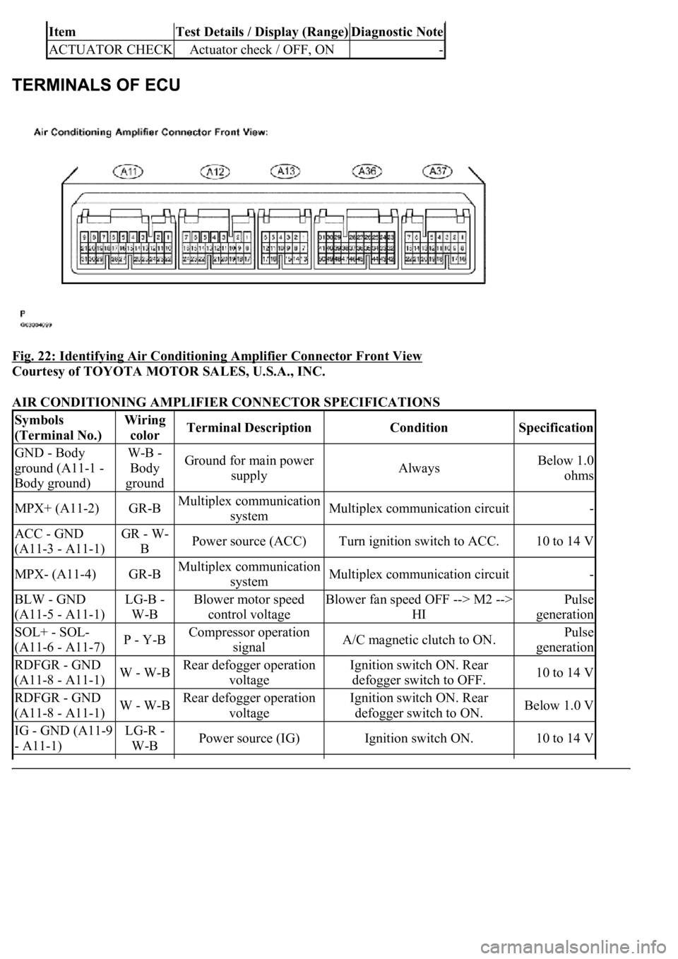
Fig. 22: Identifying Air Conditioning Amplifier Connector Front View
Courtesy of TOYOTA MOTOR SALES, U.S.A., INC.
AIR CONDITIONING AMPLIFIER CONNECTOR SPECIFICATIONS
ItemTest Details / Display (Range)Diagnostic Note
ACTUATOR CHECKActuator check / OFF, ON-
Symbols
(Terminal No.)Wiring
colorTerminal DescriptionConditionSpecification
GND - Body
ground (A11-1 -
Body ground)W-B -
Body
groundGround for main power
supplyAlwaysBelow 1.0
ohms
MPX+ (A11-2)GR-BMultiplex communication
systemMultiplex communication circuit-
ACC - GND
(A11-3 - A11-1)GR - W-
BPower source (ACC)Turn ignition switch to ACC.10 to 14 V
MPX- (A11-4)GR-BMultiplex communication
systemMultiplex communication circuit-
BLW - GND
(A11-5 - A11-1)LG-B -
W-BBlower motor speed
control voltageBlower fan speed OFF --> M2 -->
HIPulse
generation
SOL+ - SOL-
(A11-6 - A11-7)P - Y-BCompressor operation
signalA/C magnetic clutch to ON.Pulse
generation
RDFGR - GND
(A11-8 - A11-1)W - W-BRear defogger operation
voltageIgnition switch ON. Rear
defogger switch to OFF.10 to 14 V
RDFGR - GND
(A11-8 - A11-1)W - W-BRear defogger operation
voltageIgnition switch ON. Rear
defogger switch to ON.Below 1.0 V
IG - GND (A11-9
- A11-1)LG-R -
W-BPower source (IG)Ignition switch ON.10 to 14 V
Page 378 of 4500
Amplifier)
Courtesy of TOYOTA MOTOR SALES, U.S.A., INC.
NG: REPAIR OR REPLACE HARNESS OR CONNECTOR
OK: REPLACE AIR CONDITIONING AMPLIFIER (SEE REPLACEMENT
)
CIRCUIT DESCRIPTION
This circuit turns the servomotor and changes each damper position by receiving the signals from the A/C
amplifier assy. When the AUTO switch is on, the A/C amplifier changes the mode between "FACE", "BI-
LEVEL" and "FOOT" following the temperature setting.
WIRING DIAGRAM
Page 472 of 4500
a. The suspension control ECU operates the compressor & motor with the dryer and uses the solenoid
valves to control the vehicle height by analyzing the information based on the switches, sensors and
input signals.
b. Through the 4 height control sensors, the suspension control ECU detects the changes in the vehicle
height that results from the number of occupants or the amount of the load. Then, the suspension
control ECU controls the height control solenoid valves and the compressor & motor with the dryer
in order to automatically adjust the vehicle height to a constant (normal) level.
c. Furthermore, two vehicle heights can be selected by operating the height control switch: HI and
Normal.
d. In cases such as when the vehicle is jacked up, the auto leveling function is prohibited by turning
the ignition switch off.
If the vehicle is raised with its engine running, connect terminals OPB and CG of the DLC3 so the
vehicle height control is not carried out.
e. The absorber control switch selects the shock absorber damping force (normal or sport).
f. w/ Pre-collision safety system:
The suspension control ECU changes the stiffness of the suspension to the hardest setting by
receiving signals (collision unavoidable) from the cruise control ECU.
Function of Components
Page 476 of 4500
HINT:
By switching from normal mode into test mode, you can inspect the height control switch, absorber
control switch, front acceleration sensor and rear acceleration sensor.
When entering the test mode, the suspension control ECU sets all the test mode DTCs first.
After completing the test mode for each check item, the test mode DTCs that are determined
normal by the suspension control ECU will be erased.
The test mode DTCs for other check items may not be erased when only a certain signal is
inspected.
When the test mode returns back to the normal mode, all the test mode DTCs will be erased.
a. Procedure for Test Mode.
1. Make sure that the ignition switch is off.
2. Set each of the check items to the condition in Operation (A) in the Test mode table below.
3. Connect the hand-held tester to the DLC3.
4. Turn the ignition switch to the ON position.
5. Select the SIGNAL CHECK mode on the hand-held tester.
6. Set each of the check items to the condition in Operation (B) in the Test mode table below.
Page 496 of 4500

SHFR terminal of the height control sensor sub-assy to suspension control ECU, thus the vehicle height is
detected.
Fig. 18: Front Height Control Sensor Circuit Description
Courtesy of TOYOTA MOTOR SALES, U.S.A., INC.
HINT:
If DTC C1711, C1712, C1713 or C1714 is output, vehicle height control is suspended.
If the normal signal is output from the height control sensor sub-assy while suspending vehicle height
<004600520051005700550052004f000f000300590048004b004c0046004f00480003004b0048004c004a004b00570003004600520051005700550052004f0003004c005600030055004800560058005000480047001100030037004b004800030052005300
48005500440057004c005200510003004c005600030044004f[so resumed when the ignition switch is
turned off once, then turned on again.
Page 572 of 4500
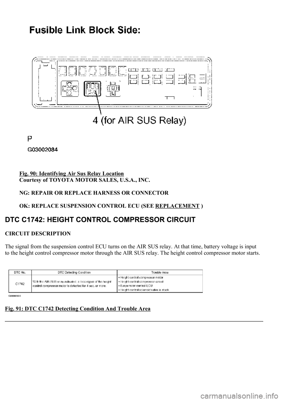
Fig. 90: Identifying Air Sus Relay Location
Courtesy of TOYOTA MOTOR SALES, U.S.A., INC.
NG: REPAIR OR REPLACE HARNESS OR CONNECTOR
OK: REPLACE SUSPENSION CONTROL ECU (SEE REPLACEMENT
)
CIRCUIT DESCRIPTION
The signal from the suspension control ECU turns on the AIR SUS relay. At that time, battery voltage is input
to the height control compressor motor through the AIR SUS relay. The height control compressor motor starts.
<0029004c004a00110003001c0014001d0003002700370026000300260014001a001700150003002700480057004800460057004c0051004a00030026005200510047004c0057004c005200510003002400510047000300370055005200580045004f004800
030024005500480044[
Page 718 of 4500

Symbols (Terminal
No.)Wiring
Color
Terminal DescriptionConditionSpecification
WFL+ (S28-3) - GND
(S30-16)LG - W-BSound signal (Front
Left)Audio system is playing-
WFR+ (S28-4) - GND
(S30-16)Y - W-BSound signal (Front
Right)Audio system is playing-
WFL-(2) (S28-9) -
GND (S30-16)L - W-BSound signal (Front
Left)Audio system is playing-
WFR-(2) (S28-10) -
GND (S30-16)B - W-BSound signal (Front
Right)Audio system is playing-
MUTE (S29-1) - GND
(S30-16)Y - W-BMute signal from radio
receiverAudio system is
sounding --> ChangingAbove 3.5 V -->
Below 3.5 V
L- (S29-2) - GND
(S30-16)G - W-BSound signal from
radio receiver (Left)Audio system is playing-
L+ (S29-3) - GND
(S30-16)R - W-BSound signal from
radio receiver (Left)Audio system is playing-
R- (S29-4) - GND
(S30-16)W - W-BSound signal from
radio receiver (Right)Audio system is playing-
R+ (S29-5) - GND
(S30-16)B - W-BSound signal from
radio receiver (Right)Audio system is playing-
TX-(1), MTX-(2) (S29-
7) - GND (S30-16)LG - W-BAVC-LAN
communication signalTurn ignition switch to
ACC2 to 3 V
TX+(1), MTX+(2)
(S29-8) - GND (S30-
16)L - W-BAVC-LAN
communication signalTurn ignition switch to
ACC2 to 3 V
ACC (S29-12) - GND
(S30-16)GR - W-BAccessory (ON)Turn ignition switch to
OFF --> ACCBelow 1 V -->
10 to 14 V
SPD (S29-11) - GND
(S30-16)O - W-BSpeed signal from
combination meterVehicle is drivingPulse generation
TXD-(1), RTX-(2)
(S29-19) - GND (S30-
16)R - W-B ((5))AVC-LAN
communication signalTurn ignition switch to
ACC2 to 3 V
TXD+(1), RTX+(2)
(S29-20) - GND (S30-
16)G - W-B ((5))AVC-LAN
communication signalTurn ignition switch to
ACC2 to 3 V
N-MUT(1), N-MU(2)
(S29-21) - GND (S30-
16)SB - W-B
(
(3))
Mute signal from radio
receiverAudio system is
sounding --> ChangingAbove 3.5 V -->
Below 3.5 V
TMUT (S29-24) -
GND (S30-16)LG - W-BMute signal from radio
receiverAudio system is
sounding --> ChangingAbove 3.5 V -->
Below 3.5 V
B+(1), +B(2) (S30-1) -
GND (S30-16)L-R - W-BBatteryAlways10 to 14 V
FL+ (S30-4) - GND LG(3), P(4) - Sound signal (Front Audio system is playing-
Page 720 of 4500

Fig. 16: Stereo Component Tuner ECU Terminal Connector
Courtesy of TOYOTA MOTOR SALES, U.S.A., INC.
TERMINAL DESCRIPTION CHART
Symbols (Terminal
No.)Wiring ColorTerminal DescriptionConditionSpecification
B (S31-1) - GND
(S31-25)L - W-BBatteryAlways10 to 14 V
SG (S31-2) - Body
groundShielded -
Body groundGroundAlwaysBelow 1 ohms
FR+ (S31-3) - GND
(S31-25)G - W-BSound signal (Front
Right)Audio system is
playing-
FL+ (S31-4) - GND
(S31-25)W - W-BSound signal (Front
Left)Audio system is
playing-
ATX+ (S31-8) -
GND (S31-25)G - W-BAVC-LAN
communication signalTurn ignition switch to
ACC2 to 3 V
MTX+ (S31-9) -
GND (S31-25)Y - W-BAVC-LAN
communication signalTurn ignition switch to
ACC2 to 3 V
UTX+ (S31-10) -
GND (S31-25)
(1)L - W-BAVC-LAN
communication signalTurn ignition switch to
ACC2 to 3 V
MUTE (S31-11) -
GND (S31-25)P - W-BMute signal from radio
receiverAudio system is
sounding -->
ChangingAbove 3.5 V -->
Below 3.5 V
ACC (S31-14) -
GND (S31-25)GR - W-BAccessory (ON)Turn ignition switch to
OFF --> ACCBelow 1 V 10 to 14
V
FR- (S31-16) - GND
(S31-25)R - W-BSound signal (Rear
Right)Audio system is
playing-
FL- (S31-17) - GND
(S31-25)B - W-BSound signal (Rear
Left)Audio system is
playing-
UTX- (S31-22) -
GND (S31-25)
(1)LG - W-BAVC-LAN
communication signalTurn ignition switch to
ACC2 to 3 V
Page 721 of 4500
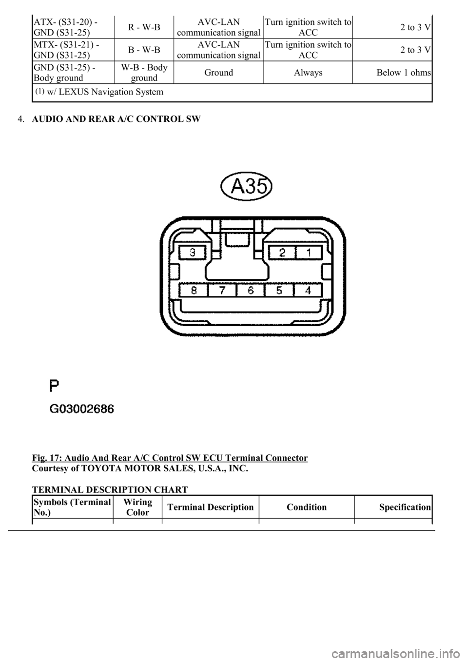
4.AUDIO AND REAR A/C CONTROL SW
Fig. 17: Audio And Rear A/C Control SW ECU Terminal Connector
Courtesy of TOYOTA MOTOR SALES, U.S.A., INC.
TERMINAL DESCRIPTION CHART
ATX- (S31-20) -
GND (S31-25)R - W-BAVC-LAN
communication signalTurn ignition switch to
ACC2 to 3 V
MTX- (S31-21) -
GND (S31-25)B - W-BAVC-LAN
communication signalTurn ignition switch to
ACC2 to 3 V
GND (S31-25) -
Body groundW-B - Body
groundGroundAlwaysBelow 1 ohms
(1)w/ LEXUS Navigation System
Symbols (Terminal
No.)Wiring
ColorTerminal DescriptionConditionSpecification