airbag LEXUS LS430 2003 Factory Owner's Manual
[x] Cancel search | Manufacturer: LEXUS, Model Year: 2003, Model line: LS430, Model: LEXUS LS430 2003Pages: 4500, PDF Size: 87.45 MB
Page 3016 of 4500
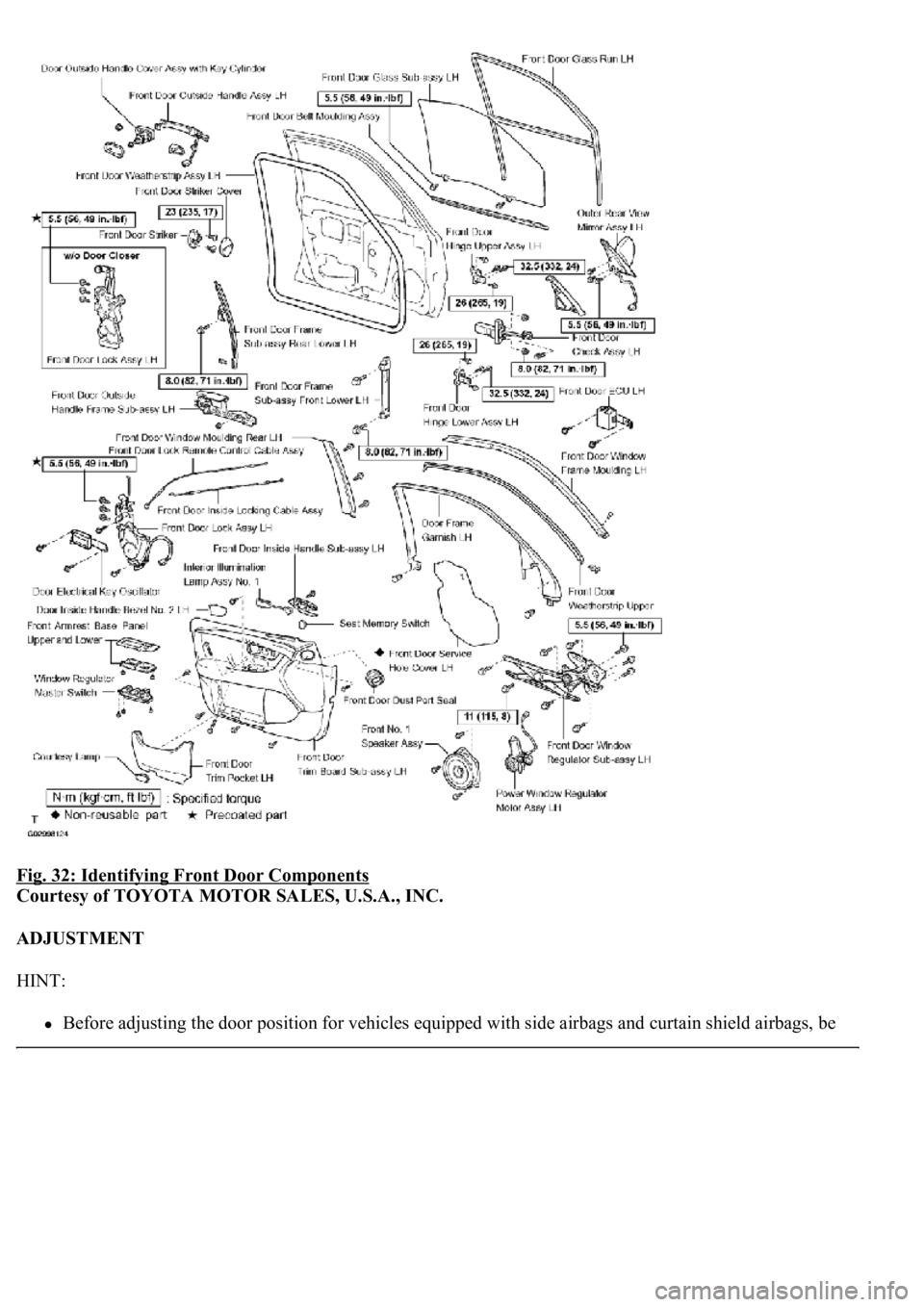
Fig. 32: Identifying Front Door Components
Courtesy of TOYOTA MOTOR SALES, U.S.A., INC.
ADJUSTMENT
HINT:
Before adjusting<00030057004b0048000300470052005200550003005300520056004c0057004c005200510003004900520055000300590048004b004c0046004f004800560003004800540058004c00530053004800470003005a004c0057004b00030056004c0047004800
030044004c005500450044[gs and curtain shield airbags, be
Page 3017 of 4500
sure to disconnect the battery. After adjustment, inspect the SRS warning lamp, the side airbag system
and the curtain shield airbag system for normal operation (see DIAGNOSIS SYSTEM
). Then initialize
both airbag systems (see INITIALIZATION
).
<00380056004800030057004b0048000300560044005000480003005300550052004600480047005800550048000300490052005500030057004b004800030035002b00030056004c0047004800030044005100470003002f002b00030056004c0047004800
1100030003[
The procedures listed below are for the LH side.
Centering bolts are used to mount the door hinge to the vehicle body and door. The door cannot be
adjusted with the centering bolts on. Substitute the centering bolts with standard bolts (w/washers) when
making adjustments.
A bolt without a torque specification is shown in the standard bolt chart (see STANDARD BOLT ).
Fig. 33: Identifying Centering Bolts
Courtesy of TOYOTA MOTOR SALES, U.S.A., INC.
1.INSPECT FRONT DOOR PANEL SUB-ASSY LH
a. Check that the clearance is within the standard ran
ge.
Page 3072 of 4500
Before adjusting the door position for vehicles equipped with side airbags and curtain shield airbags, be
sure to disconnect the battery. After adjustment, inspect the SRS warning lamp, the side airbag system
and the curtain shield airbag system for normal operation (see DIAGNOSIS SYSTEM
). Then initialize
both systems (see INITIALIZATION
).
<00380056004800030057004b0048000300560044005000480003005300550052004600480047005800550048000300490052005500030057004b004800030035002b00030056004c0047004800030044005100470003002f002b00030056004c0047004800
1100030003[
The procedures listed below are for the LH side.
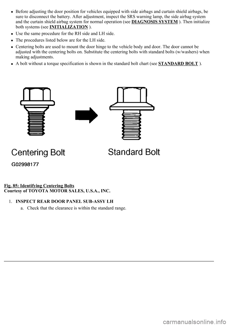
Centering bolts are used to mount the door hinge to the vehicle body and door. The door cannot be
adjusted with the centering bolts on. Substitute the centering bolts with standard bolts (w/washers) when
making adjustments.
A bolt without a torque specification is shown in the standard bolt chart (see STANDARD BOLT ).
Fig. 85: Identifying Centering Bolts
Courtesy of TOYOTA MOTOR SALES, U.S.A., INC.
1.INSPECT REAR DOOR PANEL SUB-ASSY LH
a. Check that the clearance is within the standard ran
ge.
Page 4258 of 4500
Installation is in the reverse order of removal.
See COMPONENTS .
1.DISCONNECT NEGATIVE TERMINAL CABLE FROM BATTERY
2.REMOVE FRONT DOOR SCUFF PLATE LH (See REPLACEMENT
)
3.REMOVE FRONT PILLAR GARNISH LH (See step 33 in REPLACEMENT
)
4.REMOVE INSTRUMENT PANEL UNDER COVER SUB-ASSY NO. 2 (See step 21 in
REPLACEMENT
)
5.REMOVE INSTRUMENT PANEL GARNISH SUB-ASSY RH (See step 22 in REPLACEMENT
)
6.REMOVE GLOVE COMPARTMENT DOOR ASSY W/ INSTRUMENT PANEL AIRBAG ASSY
LOWER NO. 2 (See step 25 in REPLACEMENT
)
7.REMOVE AIR SUSPENSION AND HEADLIGHT BEAM LEVEL CONTROL ECU
a. Disconnect the connectors.
b. Remove the 2 nuts and air suspension and headlight beam level control ECU.
8.REMOVE BLOWER ASSY
a. Disconnect the connectors.
b. Remove the nut and 3 bolts.
c. Remove the blower assy.
Page 4351 of 4500
PRECAUTION
1. HANDLING PRECAUTIONS FOR STEERING SYSTEM
a. Care must be taken when replacing parts. Incorrect replacement could affect the performance of the
steering system and result in a driving hazard.
2. HANDLING PRECAUTIONS FOR SRS AIRBAG SYSTEM
a. The LS430 is equipped with SRS (Supplemental Restraint System) such as the driver airbag and
front passenger airbag, etc. Failure to carry out service operations in the correct sequence could
cause the SRS to unexpectedly deploy during servicing, possibly leading to a serious accident.
Before servicing (including removal or installation of parts, inspection or replacement), be sure to
read the precautionary notice for the supplemental restraint system (see PRECAUTION
).
REPLACEMENT
HINT:
COMPONENTS: SEE COMPONENTS
Installation is in the reverse order of removal.
A bolt without a torque specification is shown in the standard bolt chart (see STANDARD BOLT ).
1. TABLE OF BOLT, SCREW AND NUT
HINT:
The bolts, screws and nuts, necessary for installation and removal of the instrument panel, are shown in
the illustration below with alphabet code.
Page 4362 of 4500

Fig. 14: Removing Glove Compartment Hole Cover
Courtesy of TOYOTA MOTOR SALES, U.S.A., INC.
25.REMOVE GLOVE Compartment DOOR ASSY W/Instrument PANEL AIRBAG ASSY LOWER
NO.2
a. Remove the 3 bolts < J > and the 3 screws.
b. Disengage the clip and remove the glove compartment door assy w/instrument panel airbag assy
lower No.2.
c. Disconnect the connectors.
Page 4363 of 4500
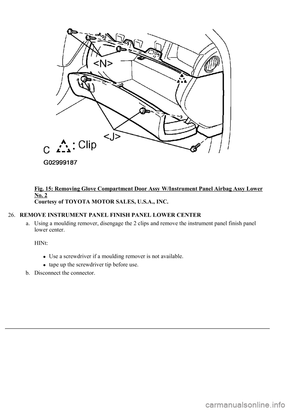
Fig. 15: Removing Glove Compartment Door Assy W/Instrument Panel Airbag Assy Lower
No. 2
Courtesy of TOYOTA MOTOR SALES, U.S.A., INC.
26.REMOVE INSTRUMENT PANEL FINISH PANEL LOWER CENTER
a. Using a moulding remover, disengage the 2 clips and remove the instrument panel finish panel
lower center.
HINt:
Use a screwdriver if a moulding remover is not available.
tape up the screwdriver tip before use.
b. Disconnect the connector.
Page 4385 of 4500
Fig. 37: Removing Instrument Panel Speaker Panel Sub-Assy No.1
Courtesy of TOYOTA MOTOR SALES, U.S.A., INC.
66.REMOVE INSTRUMENT PANEL SPEAKER PANEL SUB-ASSY NO.2
a. Use the same procedure described in the prior step.
67.REMOVE FRONT PASSENGER AIRBAG ASSY CONNECTOR (SEE REPLACEMENT
)
68.REMOVE INSTRUMENT PANEL SAFETY PAD SUB-ASSY
69.INSTALL FRONT PASSENGER AIRBAG ASSY CONNECTOR
70.INSTALL INSTRUMENT PANEL SAFETY PAD SUB-ASSY W/REINFORCEMENT ASSY
a. Install the instrument panel safety pad sub-assy w/reinforcement assy with the 9 bolts < A >, < C >,
< D >.
torque: 20 N.m (204 kgf.cm, 15 ft.Ibf)
Page 4387 of 4500
Fig. 39: Installing Instrument Panel Safety Pad Sub-Assy W/Reinforcement Assy
Courtesy of TOYOTA MOTOR SALES, U.S.A., INC.
71.INSTALL STEERING COLUMN ASSY (SEE OVERHAUL
)
SSt 09921-00010
72.INSTALL INSTRUMENT PANEL AIR BAG ASSY LOWER NO.1
a. Connect the connectors.
b. Engage the clip and install the glove compartment door assy w/instrument panel airbag assy lower
No.2 with the 3 bolts < J > and the 3 screws < N >.
torque: 10 N.m (102 kgf.cm, 7 ft.Ibf)