display LEXUS LS430 2003 Factory Owner's Manual
[x] Cancel search | Manufacturer: LEXUS, Model Year: 2003, Model line: LS430, Model: LEXUS LS430 2003Pages: 4500, PDF Size: 87.45 MB
Page 55 of 4500
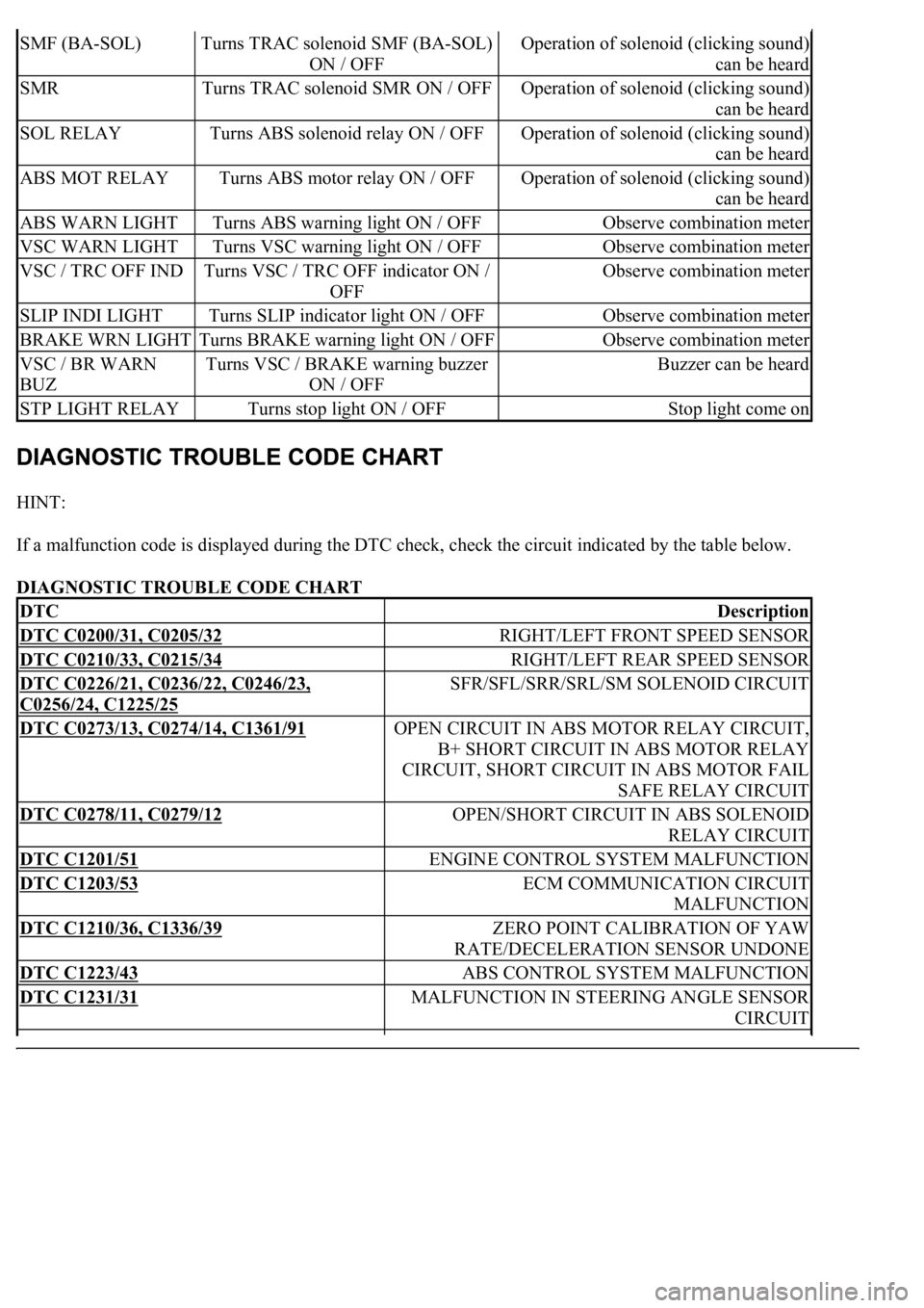
HINT:
If a malfunction code is displayed during the DTC check, check the circuit indicated by the table below.
DIAGNOSTIC TROUBLE CODE CHART
SMF (BA-SOL)Turns TRAC solenoid SMF (BA-SOL)
ON / OFFOperation of solenoid (clicking sound)
can be heard
SMRTurns TRAC solenoid SMR ON / OFFOperation of solenoid (clicking sound)
can be heard
SOL RELAYTurns ABS solenoid relay ON / OFFOperation of solenoid (clicking sound)
can be heard
ABS MOT RELAYTurns ABS motor relay ON / OFFOperation of solenoid (clicking sound)
can be heard
ABS WARN LIGHTTurns ABS warning light ON / OFFObserve combination meter
VSC WARN LIGHTTurns VSC warning light ON / OFFObserve combination meter
VSC / TRC OFF INDTurns VSC / TRC OFF indicator ON /
OFFObserve combination meter
SLIP INDI LIGHTTurns SLIP indicator light ON / OFFObserve combination meter
BRAKE WRN LIGHTTurns BRAKE warning light ON / OFFObserve combination meter
VSC / BR WARN
BUZTurns VSC / BRAKE warning buzzer
ON / OFFBuzzer can be heard
STP LIGHT RELAYTurns stop light ON / OFFStop light come on
DTCDescription
DTC C0200/31, C0205/32RIGHT/LEFT FRONT SPEED SENSOR
DTC C0210/33, C0215/34RIGHT/LEFT REAR SPEED SENSOR
DTC C0226/21, C0236/22, C0246/23,
C0256/24, C1225/25
SFR/SFL/SRR/SRL/SM SOLENOID CIRCUIT
DTC C0273/13, C0274/14, C1361/91OPEN CIRCUIT IN ABS MOTOR RELAY CIRCUIT,
B+ SHORT CIRCUIT IN ABS MOTOR RELAY
CIRCUIT, SHORT CIRCUIT IN ABS MOTOR FAIL
SAFE RELAY CIRCUIT
DTC C0278/11, C0279/12OPEN/SHORT CIRCUIT IN ABS SOLENOID
RELAY CIRCUIT
DTC C1201/51ENGINE CONTROL SYSTEM MALFUNCTION
DTC C1203/53ECM COMMUNICATION CIRCUIT
MALFUNCTION
DTC C1210/36, C1336/39ZERO POINT CALIBRATION OF YAW
RATE/DECELERATION SENSOR UNDONE
DTC C1223/43ABS CONTROL SYSTEM MALFUNCTION
DTC C1231/31MALFUNCTION IN STEERING ANGLE SENSOR
CIRCUIT
Page 63 of 4500
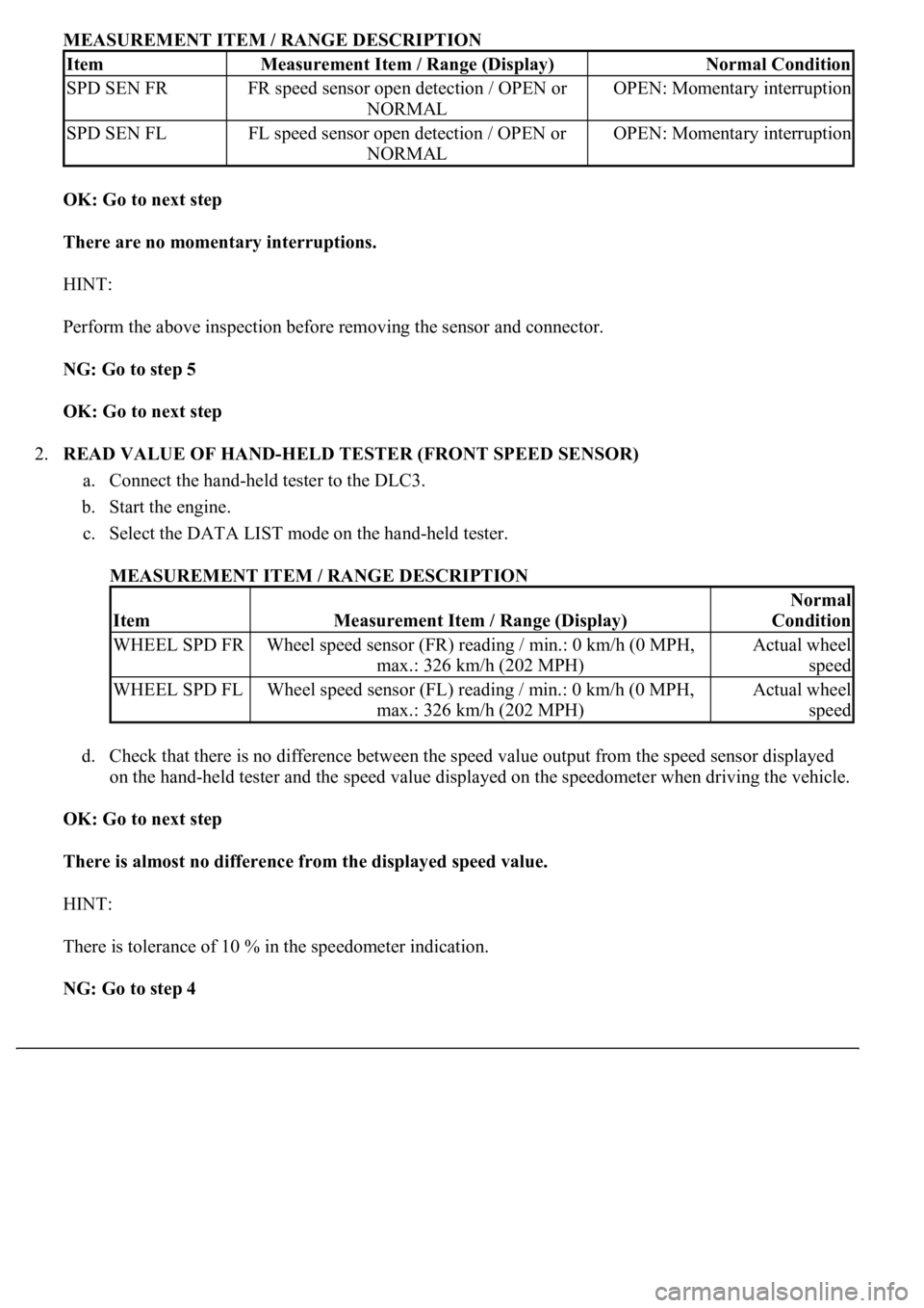
MEASUREMENT ITEM / RANGE DESCRIPTION
OK: Go to next step
There are no momentary interruptions.
HINT:
Perform the above inspection before removing the sensor and connector.
NG: Go to step 5
OK: Go to next step
2.READ VALUE OF HAND-HELD TESTER (FRONT SPEED SENSOR)
a. Connect the hand-held tester to the DLC3.
b. Start the engine.
c. Select the DATA LIST mode on the hand-held tester.
MEASUREMENT ITEM / RANGE DESCRIPTION
d. Check that there is no difference between the speed value output from the speed sensor displayed
on the hand-held tester and the speed value displayed on the speedometer when driving the vehicle.
OK: Go to next step
There is almost no difference from the displayed speed value.
HINT:
There is tolerance of 10 % in the speedometer indication.
NG: Go to step 4
ItemMeasurement Item / Range (Display)Normal Condition
SPD SEN FRFR speed sensor open detection / OPEN or
NORMALOPEN: Momentary interruption
SPD SEN FLFL speed sensor open detection / OPEN or
NORMALOPEN: Momentary interruption
ItemMeasurement Item / Range (Display)
Normal
Condition
WHEEL SPD FRWheel speed sensor (FR) reading / min.: 0 km/h (0 MPH,
max.: 326 km/h (202 MPH)Actual wheel
speed
WHEEL SPD FLWheel speed sensor (FL) reading / min.: 0 km/h (0 MPH,
max.: 326 km/h (202 MPH)Actual wheel
speed
Page 75 of 4500
corresponding to a DTC (see CHECK FOR INTERMITTENT PROBLEMS ).
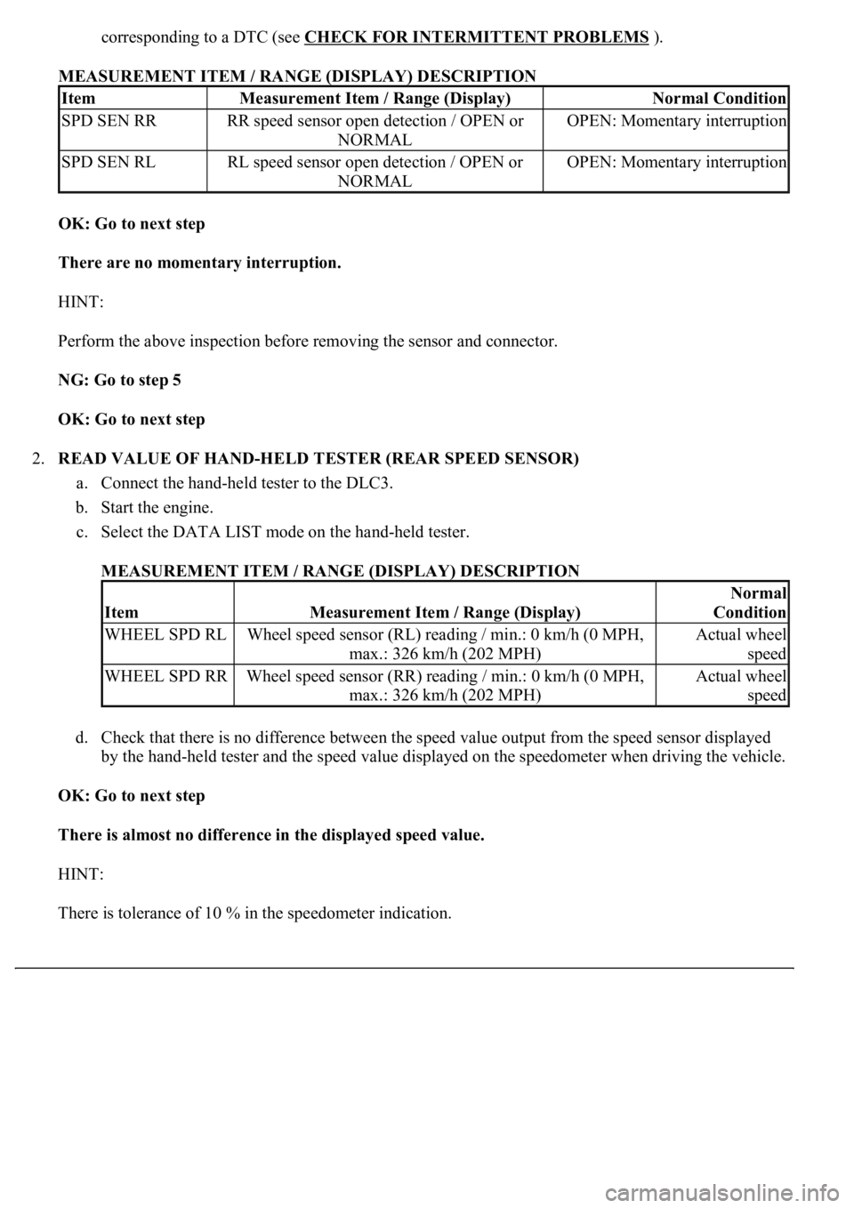
MEASUREMENT ITEM / RANGE (DISPLAY) DESCRIPTION
OK: Go to next step
There are no momentary interruption.
HINT:
Perform the above inspection before removing the sensor and connector.
NG: Go to step 5
OK: Go to next step
2.READ VALUE OF HAND-HELD TESTER (REAR SPEED SENSOR)
a. Connect the hand-held tester to the DLC3.
b. Start the engine.
c. Select the DATA LIST mode on the hand-held tester.
MEASUREMENT ITEM / RANGE (DISPLAY) DESCRIPTION
d. Check that there is no difference between the speed value output from the speed sensor displayed
by the hand-held tester and the speed value displayed on the speedometer when driving the vehicle.
OK: Go to next step
There is almost no difference in the displayed speed value.
HINT:
There is tolerance of 10 % in the speedometer indication.
ItemMeasurement Item / Range (Display)Normal Condition
SPD SEN RRRR speed sensor open detection / OPEN or
NORMALOPEN: Momentary interruption
SPD SEN RLRL speed sensor open detection / OPEN or
NORMALOPEN: Momentary interruption
ItemMeasurement Item / Range (Display)
Normal
Condition
WHEEL SPD RLWheel speed sensor (RL) reading / min.: 0 km/h (0 MPH,
max.: 326 km/h (202 MPH)Actual wheel
speed
WHEEL SPD RRWheel speed sensor (RR) reading / min.: 0 km/h (0 MPH,
max.: 326 km/h (202 MPH)Actual wheel
speed
Page 102 of 4500

HINT:
It is suspect that the DTCs output was caused by the poor connection on the connector terminal.
OK: REPLACE ABS & TRACTION ACTUATOR ASSY (SEE REPLACEMENT
)
CIRCUIT DESCRIPTION
If trouble occurs in the engine control system, the ECM transmits the abnormality to the skid control ECU. The
skid control ECU sets this DTC and the skid control ECU prohibits TRAC and VSC control.
DTC DETECTING CONDITION DESCRIPTION
INSPECTION PROCEDURE
1.CHECK HARNESS AND CONNECTOR (MOMENTARY INTERRUPTION)
a. Using the hand-held tester, check for any momentary interruption in the wire harness and connector
corresponding to a DTC (see CHECK FOR INTERMITTENT PROBLEMS
).
MEASUREMENT ITEM / RANGE (DISPLAY) DESCRIPTION
OK: Go to next step
There are no momentary interruptions.
HINT:
Perform the above inspection before removing the sensor and connector.
NG: REPAIR OR REPLACE HARNESS OR CONNECTOR (ECM - SKID CONTROL ECU)
OK: Go to next step
2.CHECK DTC FOR ENGINE
a. Check if the normal code is recorded for en
gine control system.
DTC No.DTC Detecting ConditionTrouble Area
C1201/51At the engine speed of 500 RPM, a trouble signal in the engine
control system continues for 5 secs, or more.Engine control
system
ItemMeasurement Item / Range (Display)Normal Condition
EFI COMEFI communication open detectionOPEN: Momentary interruption
Page 108 of 4500
When U0121/94, U0123/62, U0124/95 or U0126/63 are output together with C1231/31, inspect and
repair the trouble areas indicated by U0121/94, U0123/62, U0124/95 or U0126/63 first.
When the speed sensor or the yaw rate sensor has trouble, DTCs for the steering angle sensor may be
output even when the steering angle sensor is normal. When DTCs for the speed sensor or yaw rate
sensor are output together with other DTCs for the steering angle sensor, inspect and repair the speed
sensor and yaw rate sensor first, and then inspect and repair the steering angle sensor.
1.CHECK HARNESS AND CONNECTOR (MOMENTARY INTERRUPTION)
a. Using the hand-held tester, check for any momentary interruption in the wire harness and
connectors between the skid control ECU and steering angle sensor (see CHECK FOR
INTERMITTENT PROBLEMS ).
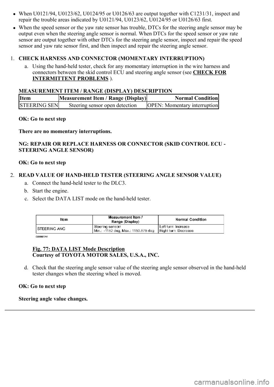
MEASUREMENT ITEM / RANGE (DISPLAY) DESCRIPTION
OK: Go to next step
There are no momentary interruptions.
NG: REPAIR OR REPLACE HARNESS OR CONNECTOR (SKID CONTROL ECU -
STEERING ANGLE SENSOR)
OK: Go to next step
2.READ VALUE OF HAND-HELD TESTER (STEERING ANGLE SENSOR VALUE)
a. Connect the hand-held tester to the DLC3.
b. Start the engine.
c. Select the DATA LIST mode on the hand-held tester.
Fig. 77: DATA LIST Mode Description
Courtesy of TOYOTA MOTOR SALES, U.S.A., INC.
d. Check that the steering angle sensor value of the steering angle sensor observed in the hand-held
tester changes when the steering wheel is moved.
OK: Go to next step
Steering angle value changes.
ItemMeasurement Item / Range (Display)Normal Condition
STEERING SENSteering sensor open detectionOPEN: Momentary interruption
Page 125 of 4500

OK: Go to next step
2.INSPECT BATTERY
a. Check the battery voltage.
Standard:
Voltage: 10 to 14 V
NG: INSPECT CHARGING SYSTEM (SEE ON
-VEHICLE INSPECTION )
OK: Go to next step
3.INSPECT SKID CONTROL ECU TERMINAL VOLTAGE (IG1 TERMINAL)
a. Connect the hand-held tester to the DLC3.
b. Start the engine.
c. Select the DATA LIST mode on the hand-held tester.
Fig. 91: DATA LIST Mode Description
Courtesy of TOYOTA MOTOR SALES, U.S.A., INC.
d. Read the voltage condition output from the ECU displayed on the hand-held tester.
Standard:
"Normal" is displayed.
NG: Go to step 4
OK: REPLACE ABS & TRACTION ACTUATOR ASSY (SEE REPLACEMENT
)
4.INSPECT SKID CONTROL ECU CONNECTOR (GND TERMINAL CONTINUITY)
a. Disconnect the skid control ECU connector.
b. Measure the resistance according to the value (s) in the table below.
Standard:
Page 128 of 4500

c. Select the DATA LIST mode on the hand-held tester.
MEASUREMENT ITEM / RANGE (DISPLAY) DESCRIPTION
d. Check that the brake fluid pressure value of the master cylinder pressure sensor observed in the
hand held tester changes when the brake pedal is depressed.
OK: Go to next step
When the pedal is depressed, displayed voltage on the hand-held tester increases.
NG: Go to step 2
OK: REPLACE ABS & TRACTION ACTUATOR ASSY (SEE REPLACEMENT
)
2.INSPECT SKID CONTROL ECU TERMINAL VOLTAGE (STP TERMINAL)
a. Disconnect the skid control ECU connector.
b. Measure the voltage according to the value (s) in the table below.
Standard:
TESTER CONNECTION SPECIFIED CONDITION
NG: CHECK AND REPLACE STOP LIGHT SWITCH CIRCUIT
OK: REPLACE ABS & TRACTION ACTUATOR ASSY (SEE REPLACEMENT
)
ItemMeasurement Item / Range (Display)Normal Condition
MAS CYL PRS
1Master cylinder pressure sensor 1 reading /
min.: 0 V, max.: 5 VWhen brake pedal is released:
0.3 to 0.9V
Tester ConnectionSwitch ConditionSpecified Condition
S42-27 (STP) - Body groundBrake pedal depressed8 to 14V
S42-27 (STP) - Body groundBrake pedal releasedBelow 1 V
Page 145 of 4500
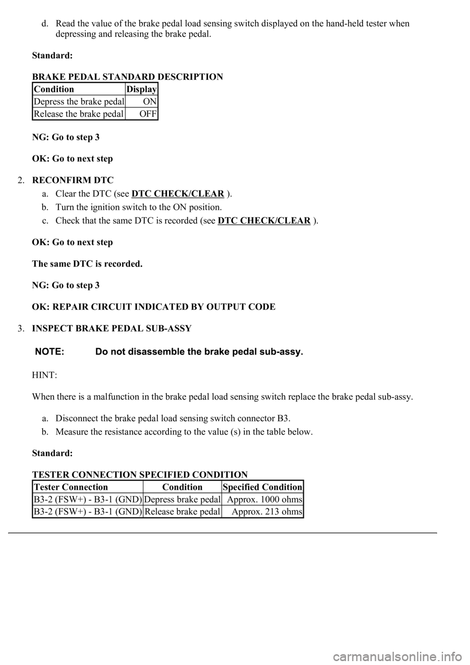
d. Read the value of the brake pedal load sensing switch displayed on the hand-held tester when
depressing and releasing the brake pedal.
Standard:
BRAKE PEDAL STANDARD DESCRIPTION
NG: Go to step 3
OK: Go to next step
2.RECONFIRM DTC
a. Clear the DTC (see DTC CHECK/CLEAR
).
b. Turn the ignition switch to the ON position.
c. Check that the same DTC is recorded (see DTC CHECK/CLEAR
).
OK: Go to next step
The same DTC is recorded.
NG: Go to step 3
OK: REPAIR CIRCUIT INDICATED BY OUTPUT CODE
3.INSPECT BRAKE PEDAL SUB-ASSY
HINT:
When there is a malfunction in the brake pedal load sensing switch replace the brake pedal sub-assy.
a. Disconnect the brake pedal load sensing switch connector B3.
b. Measure the resistance according to the value (s) in the table below.
Standard:
TESTER CONNECTION SPECIFIED CONDITION
ConditionDisplay
Depress the brake pedalON
Release the brake pedalOFF
Tester ConnectionConditionSpecified Condition
B3-2 (FSW+) - B3-1 (GND)Depress brake pedalApprox. 1000 ohms
B3-2 (FSW+) - B3-1 (GND)Release brake pedalApprox. 213 ohms
Page 151 of 4500
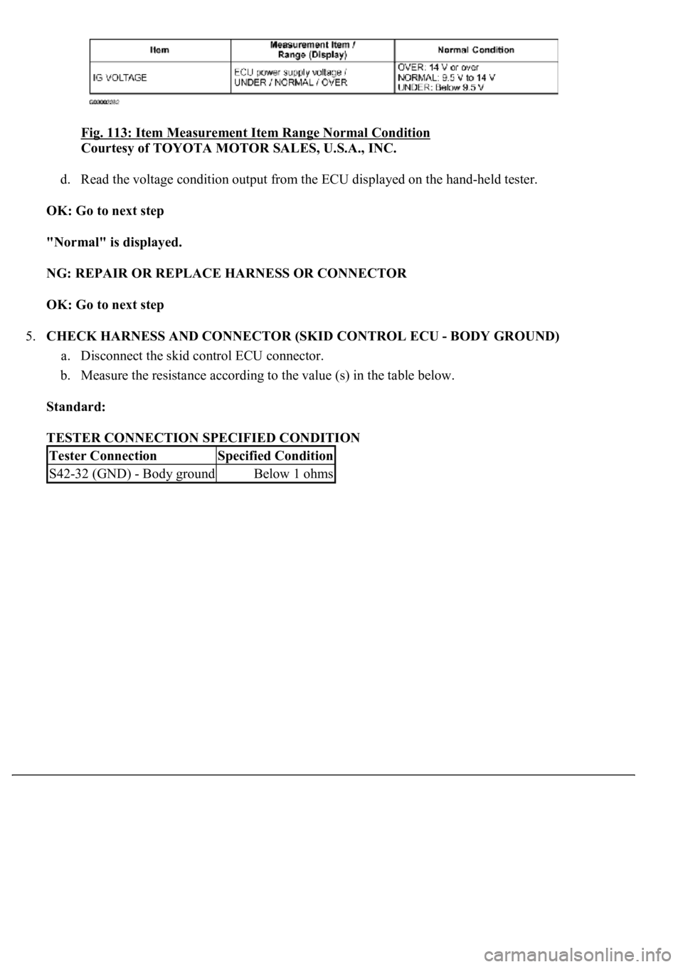
<0029004c004a00110003001400140016001d0003002c0057004800500003003000480044005600580055004800500048005100570003002c0057004800500003003500440051004a0048000300310052005500500044004f00030026005200510047004c00
57004c00520051[
Courtesy of TOYOTA MOTOR SALES, U.S.A., INC.
d. Read the voltage condition output from the ECU displayed on the hand-held tester.
OK: Go to next step
"Normal" is displayed.
NG: REPAIR OR REPLACE HARNESS OR CONNECTOR
OK: Go to next step
5.CHECK HARNESS AND CONNECTOR (SKID CONTROL ECU - BODY GROUND)
a. Disconnect the skid control ECU connector.
b. Measure the resistance according to the value (s) in the table below.
Standard:
TESTER CONNECTION SPECIFIED CONDITION
Tester ConnectionSpecified Condition
S42-32 (GND) - Body groundBelow 1 ohms
Page 158 of 4500
d. Check the voltage condition output from the ECU displayed on the hand-held tester.
OK: Go to next step
"Normal" is displayed.
NG: REPAIR OR REPLACE HARNESS OR CONNECTOR (IG CIRCUIT)
OK: Go to next step
5.CHECK HARNESS AND CONNECTOR (SKID CONTROL ECU - BODY GROUND)
a. Disconnect the skid control ECU connector.
b. Measure the resistance according to the value (s) in the table below.
Standard:
TESTER CONNECTION SPECIFIED CONDITION
NG: REPAIR OR REPLACE HARNESS OR CONNECTOR (GND CIRCUIT)
Tester ConnectionSpecified Condition
S42-32 (GND) - Body groundBelow 1 ohms