LEXUS LS430 2003 Factory Owner's Manual
LS430 2003
LEXUS
LEXUS
https://www.carmanualsonline.info/img/36/57050/w960_57050-0.png
LEXUS LS430 2003 Factory Owner's Manual
Page 3525 of 4500
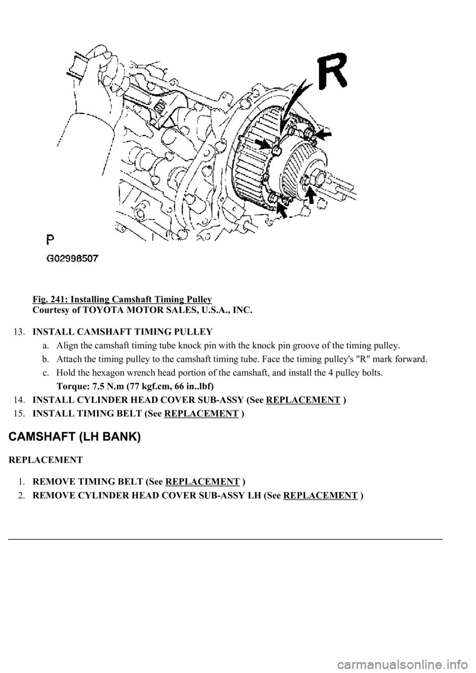
Fig. 241: Installing Camshaft Timing Pulley
Courtesy of TOYOTA MOTOR SALES, U.S.A., INC.
13.INSTALL CAMSHAFT TIMING PULLEY
a. Align the camshaft timing tube knock pin with the knock pin groove of the timing pulley.
b. Attach the timing pulley to the camshaft timing tube. Face the timing pulley's "R" mark forward.
c. Hold the hexagon wrench head portion of the camshaft, and install the 4 pulley bolts.
Torque: 7.5 N.m (77 kgf.cm, 66 in..lbf)
14.INSTALL CYLINDER HEAD COVER SUB-ASSY (See REPLACEMENT
)
15.INSTALL TIMING BELT (See REPLACEMENT
)
REPLACEMENT
1.REMOVE TIMING BELT (See REPLACEMENT
)
2.REMOVE CYLINDER HEAD COVER SUB-ASSY LH (See REPLACEMENT
)
Page 3531 of 4500
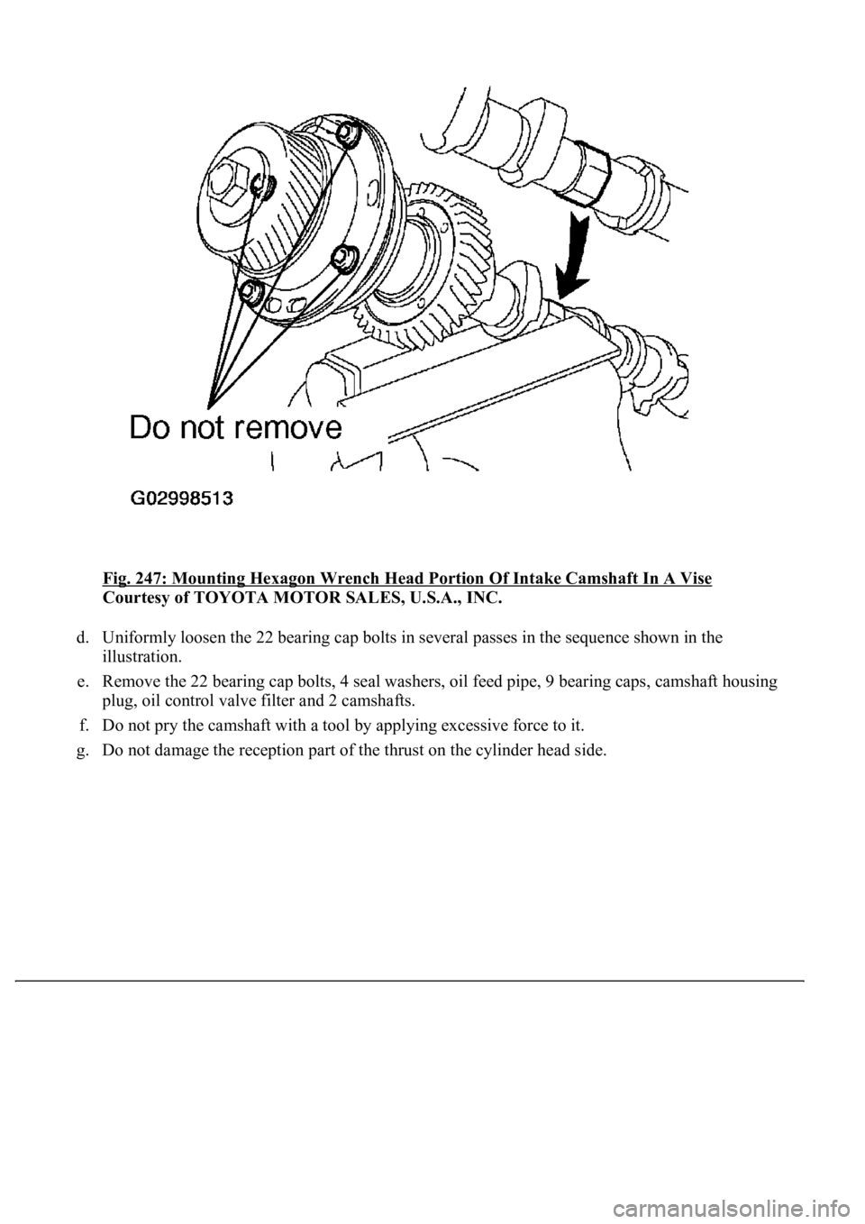
Fig. 247: Mounting Hexagon Wrench Head Portion Of Intake Camshaft In A Vise
Courtesy of TOYOTA MOTOR SALES, U.S.A., INC.
d. Uniformly loosen the 22 bearing cap bolts in several passes in the sequence shown in the
illustration.
e. Remove the 22 bearing cap bolts, 4 seal washers, oil feed pipe, 9 bearing caps, camshaft housing
plug, oil control valve filter and 2 camshafts.
f. Do not pry the camshaft with a tool by applying excessive force to it.
g. Do not damage the reception part of the thrust on the cylinder head side.
Page 3550 of 4500
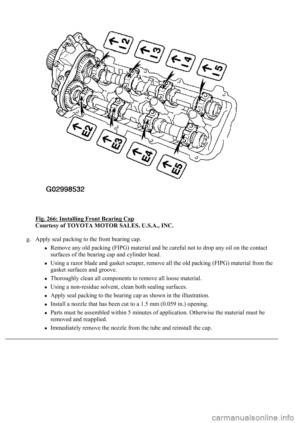
Fig. 266: Installing Front Bearing Cap
Courtesy of TOYOTA MOTOR SALES, U.S.A., INC.
g. Apply seal packing to the front bearing cap.
Remove any old packing (FIPG) material and be careful not to drop any oil on the contact
surfaces of the bearing cap and cylinder head.
Using a razor blade and gasket scraper, remove all the old packing (FIPG) material from the
gasket surfaces and groove.
Thoroughly clean all components to remove all loose material.
Using a non-residue solvent, clean both sealing surfaces.
Apply seal packing to the bearing cap as shown in the illustration.
Install a nozzle that has been cut to a 1.5 mm (0.059 in.) opening.
Parts must be assembled within 5 minutes of application. Otherwise the material must be
removed and reapplied.
Immediately remove the nozzle from the tube and reinstall the cap.
Page 3558 of 4500
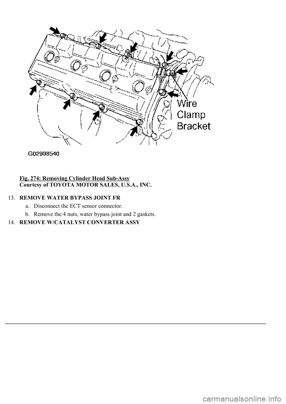
Fig. 274: Removing Cylinder Head Sub-Assy
Courtesy of TOYOTA MOTOR SALES, U.S.A., INC.
13.REMOVE WATER BYPASS JOINT FR
a. Disconnect the ECT sensor connector.
b. Remove the 4 nuts, water bypass joint and 2 gaskets.
14.REMOVE W/CATALYST CONVERTER ASSY
Page 3559 of 4500
Fig. 275: Identifying Cylinder Head Bolts
Courtesy of TOYOTA MOTOR SALES, U.S.A., INC.
15.REMOVE CYLINDER HEAD SUB-ASSY
a. Remove the bolt, and disconnect the wire clamp bracket on the engine wire from the camshaft
bearing cap.
b. Remove the EVAP from the cylinder head cover sub-assy.
c. Remove the 9 bolts, 9 seal washers, c
ylinder head cover sub-assy and gasket.
Page 3560 of 4500
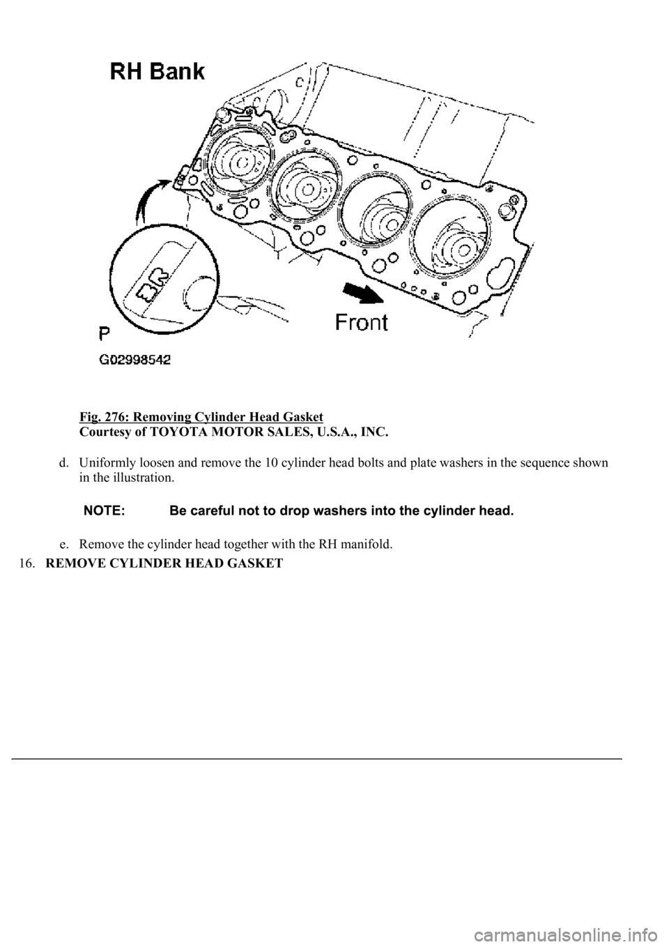
Fig. 276: Removing Cylinder Head Gasket
Courtesy of TOYOTA MOTOR SALES, U.S.A., INC.
d. Uniformly loosen and remove the 10 cylinder head bolts and plate washers in the sequence shown
in the illustration.
e. Remove the cylinder head together with the RH manifold.
16.REMOVE CYLINDER HEAD GASKET
Page 3573 of 4500
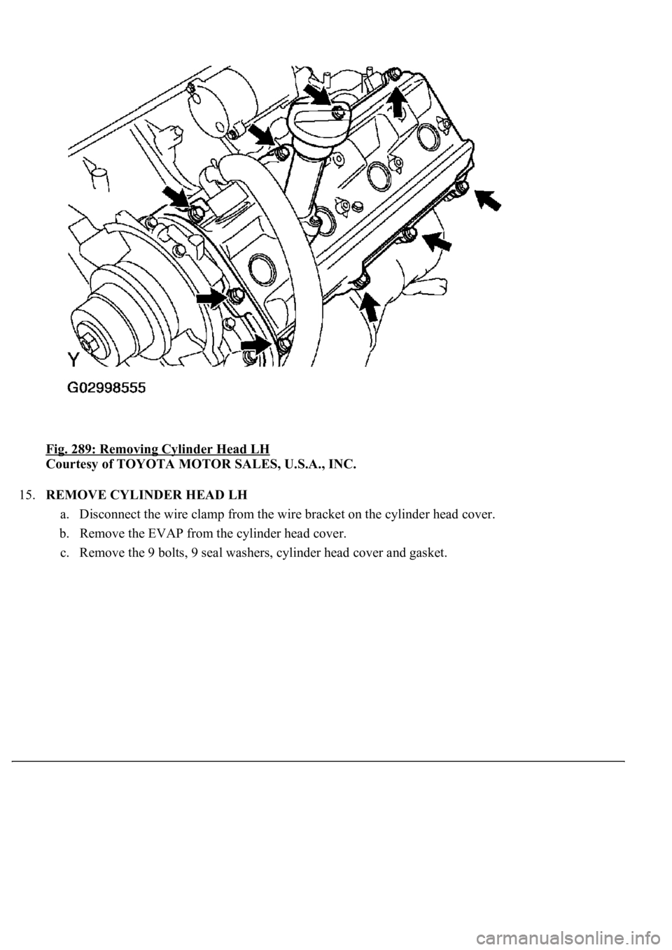
Fig. 289: Removing Cylinder Head LH
Courtesy of TOYOTA MOTOR SALES, U.S.A., INC.
15.REMOVE CYLINDER HEAD LH
a. Disconnect the wire clamp from the wire bracket on the cylinder head cover.
b. Remove the EVAP from the cylinder head cover.
c. Remove the 9 bolts, 9 seal washers, c
ylinder head cover and gasket.
Page 3574 of 4500
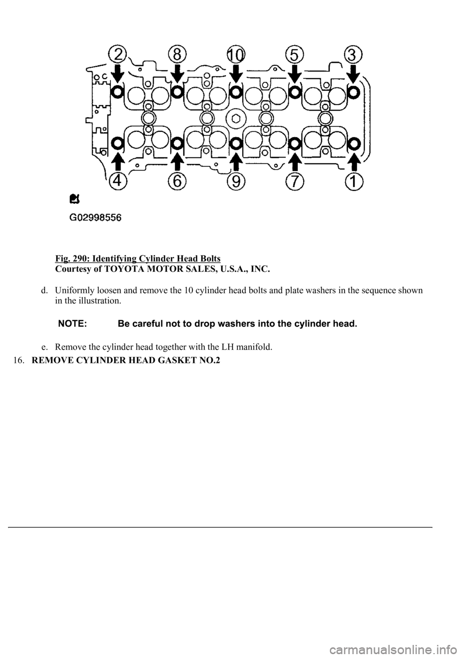
Fig. 290: Identifying Cylinder Head Bolts
Courtesy of TOYOTA MOTOR SALES, U.S.A., INC.
d. Uniformly loosen and remove the 10 cylinder head bolts and plate washers in the sequence shown
in the illustration.
e. Remove the cylinder head together with the LH manifold.
16.REMOVE CYLINDER HEAD GASKET NO.2
Page 3582 of 4500
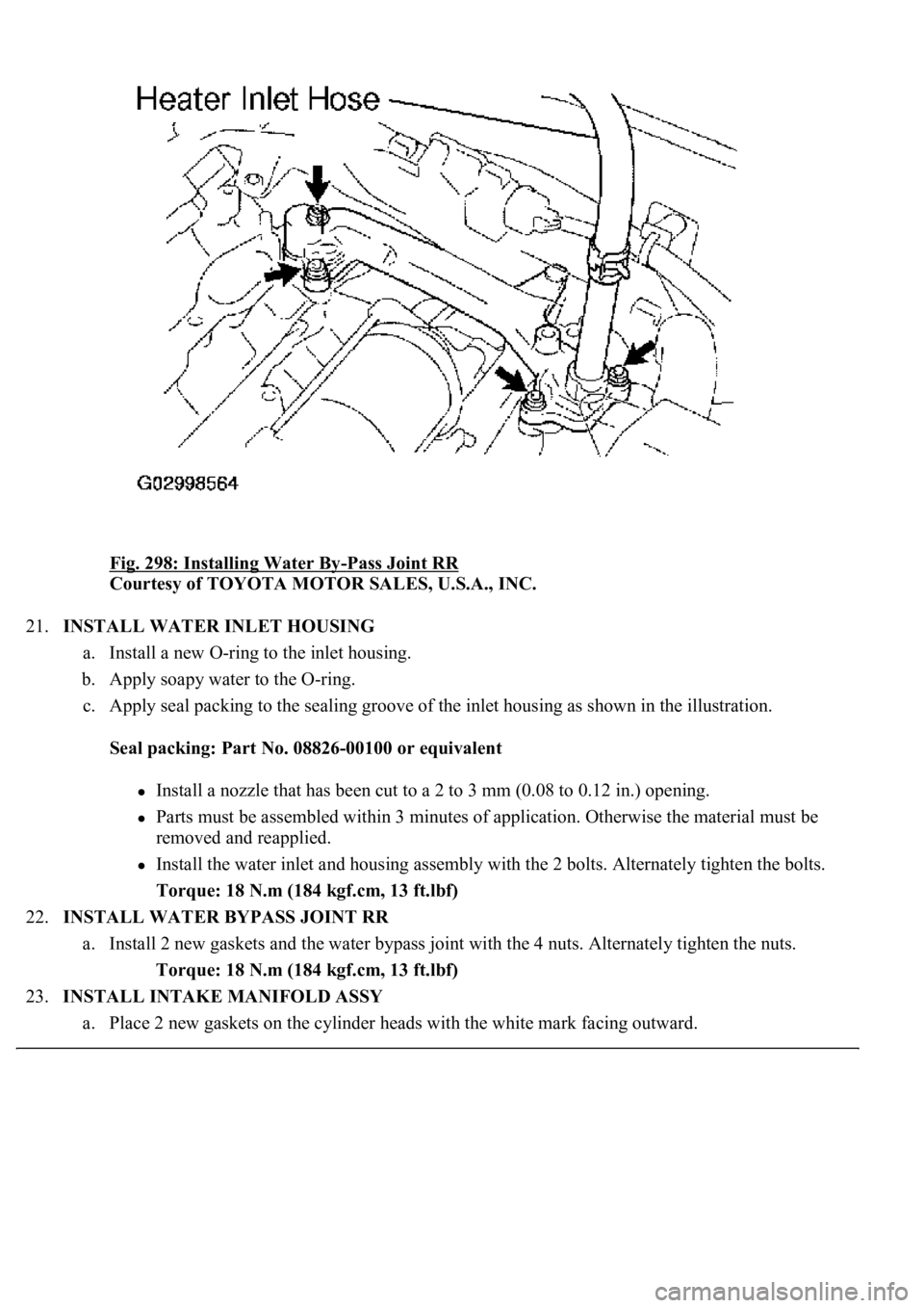
Fig. 298: Installing Water By-Pass Joint RR
Courtesy of TOYOTA MOTOR SALES, U.S.A., INC.
21.INSTALL WATER INLET HOUSING
a. Install a new O-ring to the inlet housing.
b. Apply soapy water to the O-ring.
c. Apply seal packing to the sealing groove of the inlet housing as shown in the illustration.
Seal packing: Part No. 08826-00100 or equivalent
<002c0051005600570044004f004f00030044000300510052005d005d004f004800030057004b004400570003004b00440056000300450048004800510003004600580057000300570052000300440003001500030057005200030016000300500050000300
0b001300110013001b00030057005200030013001100140015[ in.) opening.
Parts must be assembled within 3 minutes of application. Otherwise the material must be
removed and reapplied.
Install the water inlet and housing assembly with the 2 bolts. Alternately tighten the bolts.
Torque: 18 N.m (184 kgf.cm, 13 ft.lbf)
22.INSTALL WATER BYPASS JOINT RR
a. Install 2 new gaskets and the water bypass joint with the 4 nuts. Alternately tighten the nuts.
Torque: 18 N.m (184 kgf.cm, 13 ft.lbf)
23.INSTALL INTAKE MANIFOLD ASSY
a. Place 2 new gaskets on the cylinder heads with the white mark facing outward.
Page 3596 of 4500
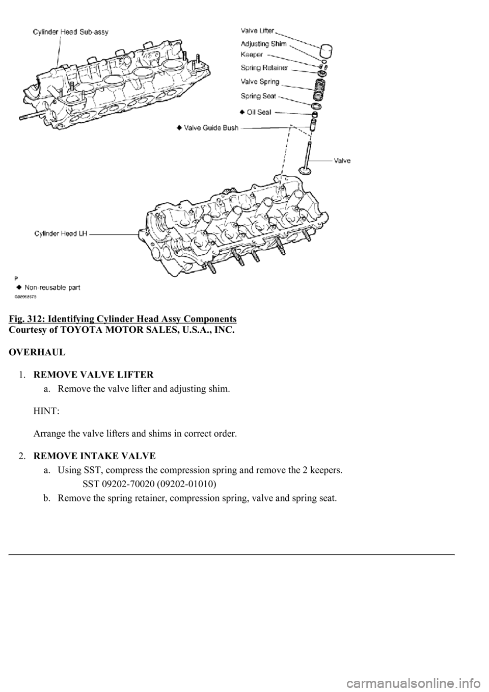
Fig. 312: Identifying Cylinder Head Assy Components
Courtesy of TOYOTA MOTOR SALES, U.S.A., INC.
OVERHAUL
1.REMOVE VALVE LIFTER
a. Remove the valve lifter and adjusting shim.
HINT:
Arrange the valve lifters and shims in correct order.
2.REMOVE INTAKE VALVE
a. Using SST, compress the compression spring and remove the 2 keepers.
SST 09202-70020 (09202-01010)
b. Remove the spring retainer, compression spring, valve and spring seat.