LEXUS LS430 2003 Factory Repair Manual
LS430 2003
LEXUS
LEXUS
https://www.carmanualsonline.info/img/36/57050/w960_57050-0.png
LEXUS LS430 2003 Factory Repair Manual
Page 2718 of 4500
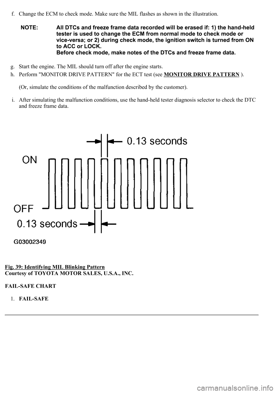
f. Change the ECM to check mode. Make sure the MIL flashes as shown in the illustration.
g. Start the engine. The MIL should turn off after the engine starts.
h. Perform "MONITOR DRIVE PATTERN" for the ECT test (see MONITOR DRIVE PATTERN
).
(Or, simulate the conditions of the malfunction described by the customer).
i. After simulating the malfunction conditions, use the hand-held tester diagnosis selector to check the DTC
and freeze frame data.
Fig. 39: Identifying MIL Blinking Pattern
Courtesy of TOYOTA MOTOR SALES, U.S.A., INC.
FAIL-SAFE CHART
1.FAIL-SAFE
Page 2719 of 4500
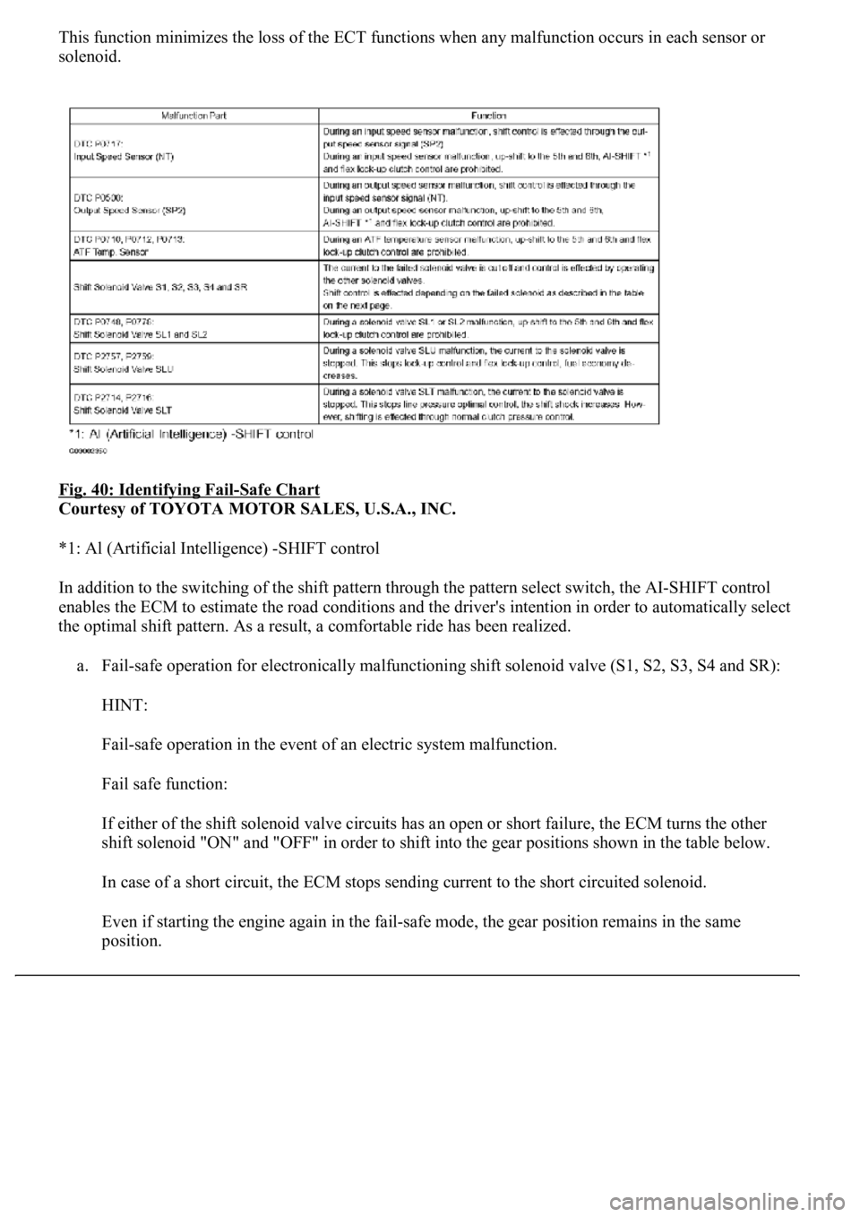
This function minimizes the loss of the ECT functions when any malfunction occurs in each sensor or
solenoid.
Fig. 40: Identifying Fail
-Safe Chart
Courtesy of TOYOTA MOTOR SALES, U.S.A., INC.
*1: Al (Artificial Intelligence) -SHIFT control
In addition to the switching of the shift pattern through the pattern select switch, the AI-SHIFT control
enables the ECM to estimate the road conditions and the driver's intention in order to automatically select
the optimal shift pattern. As a result, a comfortable ride has been realized.
a. Fail-safe operation for electronically malfunctioning shift solenoid valve (S1, S2, S3, S4 and SR):
HINT:
Fail-safe operation in the event of an electric system malfunction.
Fail safe function:
If either of the shift solenoid valve circuits has an open or short failure, the ECM turns the other
shift solenoid "ON" and "OFF" in order to shift into the gear positions shown in the table below.
In case of a short circuit, the ECM stops sending current to the short circuited solenoid.
Even if starting the engine again in the fail-safe mode, the gear position remains in the same
position.
Page 2746 of 4500
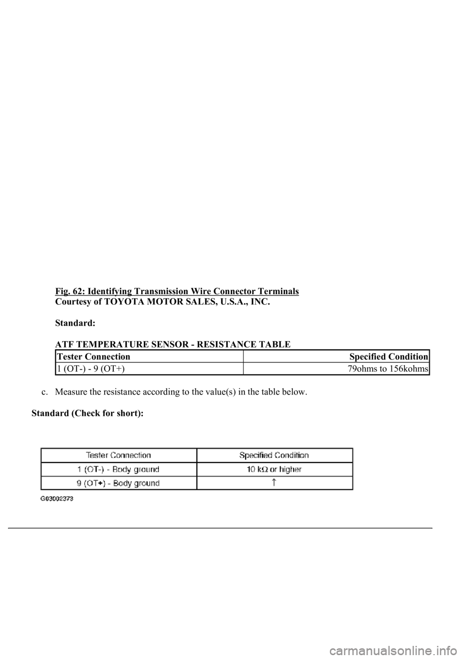
Fig. 62: Identifying Transmission Wire Connector Terminals
Courtesy of TOYOTA MOTOR SALES, U.S.A., INC.
Standard:
ATF TEMPERATURE SENSOR - RESISTANCE TABLE
c. Measure the resistance according to the value(s) in the table below.
Standard (Check for short):
Tester ConnectionSpecified Condition
1 (OT-) - 9 (OT+)79ohms to 156kohms
Page 2753 of 4500
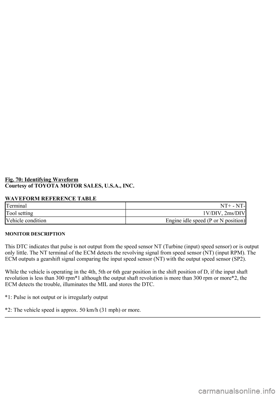
Fig. 70: Identifying Waveform
Courtesy of TOYOTA MOTOR SALES, U.S.A., INC.
WAVEFORM REFERENCE TABLE
MONITOR DESCRIPTION
This DTC indicates that pulse is not output from the speed sensor NT (Turbine (input) speed sensor) or is output
only little. The NT terminal of the ECM detects the revolving signal from speed sensor (NT) (input RPM). The
ECM outputs a gearshift signal comparing the input speed sensor (NT) with the output speed sensor (SP2).
While the vehicle is operating in the 4th, 5th or 6th gear position in the shift position of D, if the input shaft
revolution is less than 300 rpm*1 although the output shaft revolution is more than 300 rpm or more*2, the
ECM detects the trouble, illuminates the MIL and stores the DTC.
*1: Pulse is not output or is irregularly output
*2: The vehicle speed is approx. 50 km/h (31 mph) or more.
TerminalNT+ - NT-
Tool setting1V/DIV, 2ms/DIV
Vehicle conditionEngine idle speed (P or N position)
Page 2772 of 4500
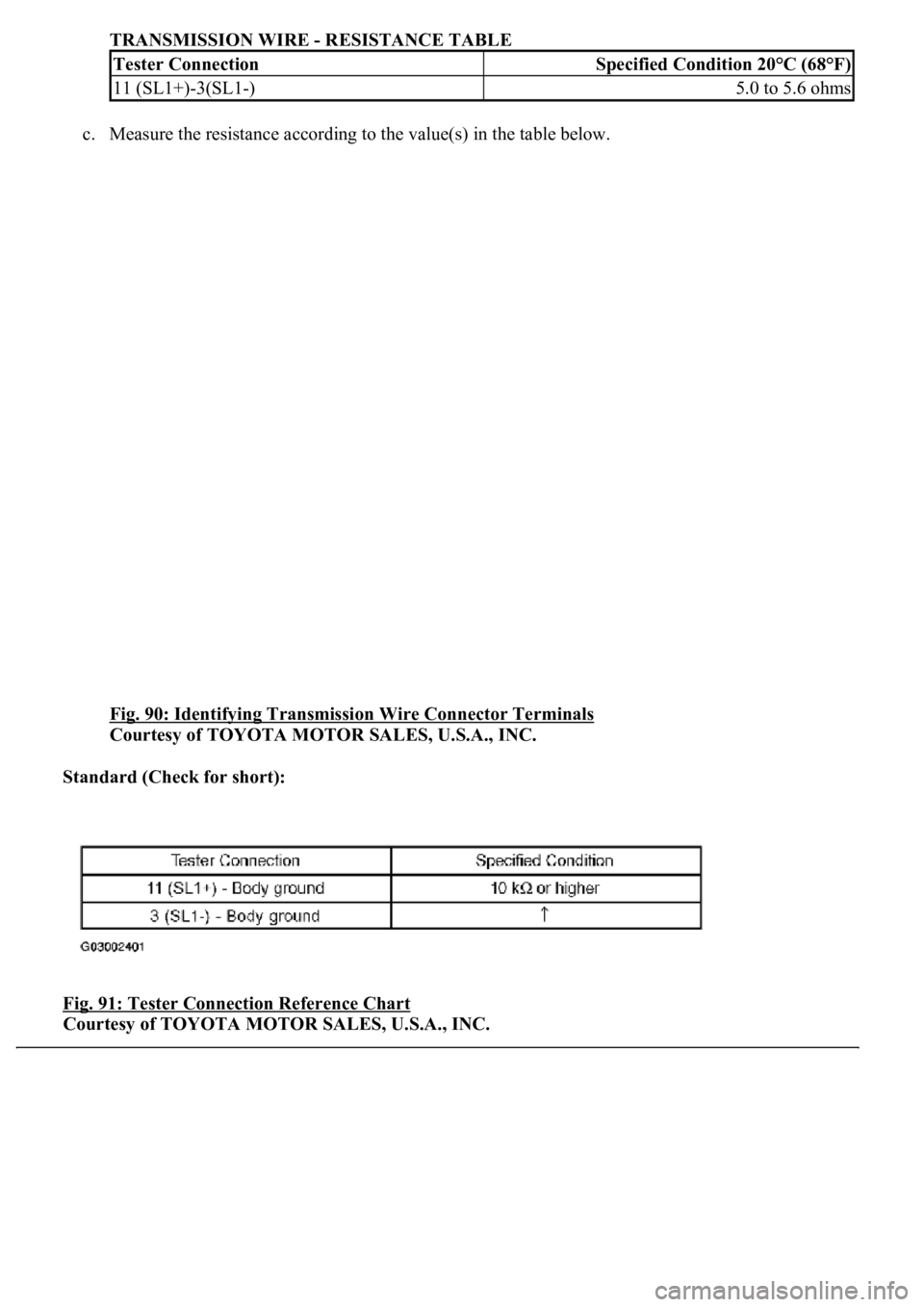
TRANSMISSION WIRE - RESISTANCE TABLE
c. Measure the resistance according to the value(s) in the table below.
Fig. 90: Identifying Transmission Wire Connector Terminals
Courtesy of TOYOTA MOTOR SALES, U.S.A., INC.
Standard (Check for short):
Fig. 91: Tester Connection Reference Chart
Courtesy of TOYOTA MOTOR SALES, U.S.A., INC.
Tester ConnectionSpecified Condition 20°C (68°F)
11 (SL1+)-3(SL1-)5.0 to 5.6 ohms
Page 2814 of 4500
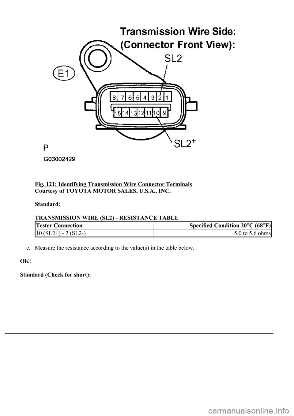
Fig. 121: Identifying Transmission Wire Connector Terminals
Courtesy of TOYOTA MOTOR SALES, U.S.A., INC.
Standard:
TRANSMISSION WIRE (SL2) - RESISTANCE TABLE
c. Measure the resistance according to the value(s) in the table below.
OK:
Standard (Check for short):
Tester ConnectionSpecified Condition 20°C (68°F)
10 (SL2+) - 2 (SL2-)5.0 to 5.6 ohms
Page 2829 of 4500
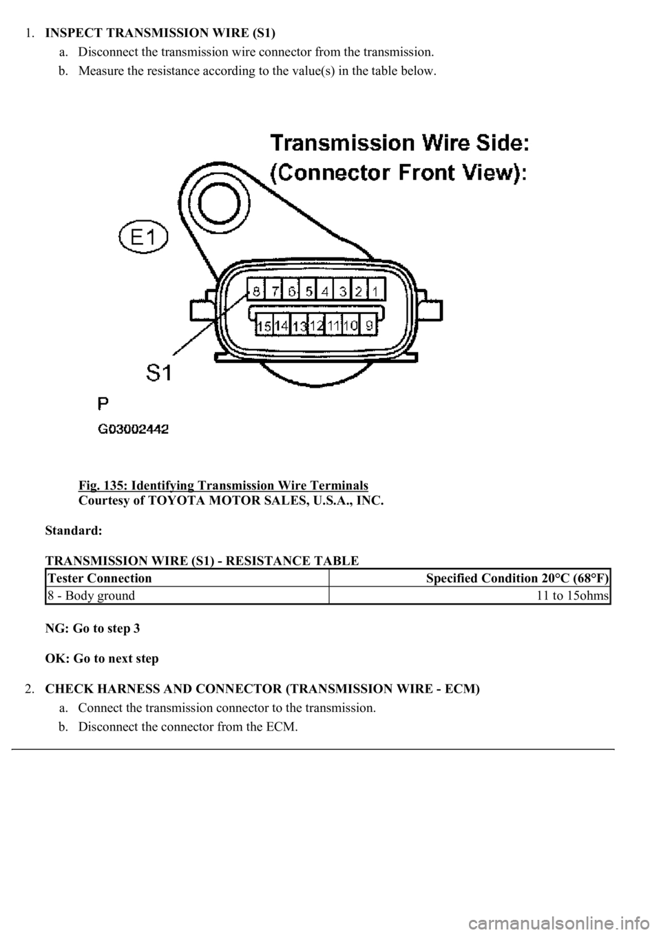
1.INSPECT TRANSMISSION WIRE (S1)
a. Disconnect the transmission wire connector from the transmission.
b. Measure the resistance according to the value(s) in the table below.
Fig. 135: Identifying Transmission Wire Terminals
Courtesy of TOYOTA MOTOR SALES, U.S.A., INC.
Standard:
TRANSMISSION WIRE (S1) - RESISTANCE TABLE
NG: Go to step 3
OK: Go to next step
2.CHECK HARNESS AND CONNECTOR (TRANSMISSION WIRE - ECM)
a. Connect the transmission connector to the transmission.
b. Disconnect the connector from the ECM.
Tester ConnectionSpecified Condition 20°C (68°F)
8 - Body ground11 to 15ohms
Page 2834 of 4500
INSPECTION PROCEDURE
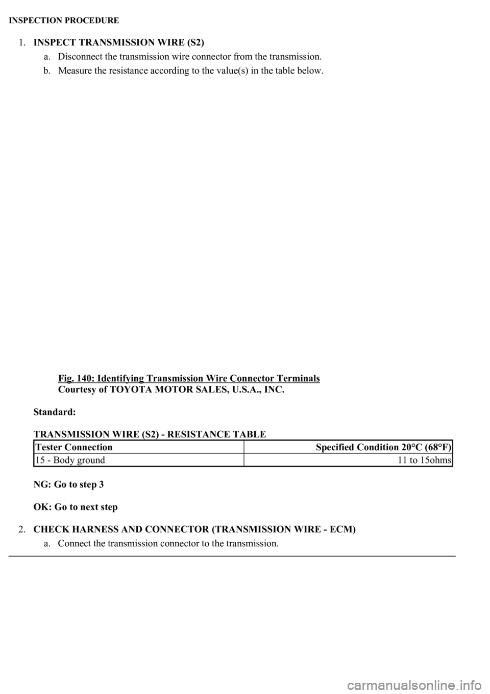
1.INSPECT TRANSMISSION WIRE (S2)
a. Disconnect the transmission wire connector from the transmission.
b. Measure the resistance according to the value(s) in the table below.
Fig. 140: Identifying Transmission Wire Connector Terminals
Courtesy of TOYOTA MOTOR SALES, U.S.A., INC.
Standard:
TRANSMISSION WIRE (S2) - RESISTANCE TABLE
NG: Go to step 3
OK: Go to next step
2.CHECK HARNESS AND CONNECTOR (TRANSMISSION WIRE - ECM)
a. Connect the transmission connector to the transmission.
Tester ConnectionSpecified Condition 20°C (68°F)
15 - Body ground11 to 15ohms
Page 2840 of 4500
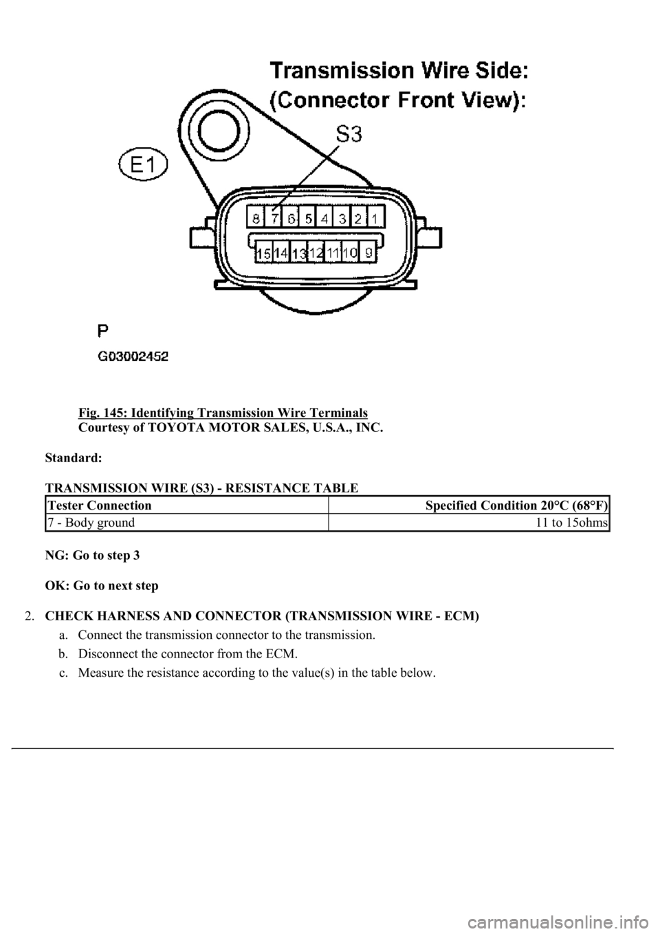
Fig. 145: Identifying Transmission Wire Terminals
Courtesy of TOYOTA MOTOR SALES, U.S.A., INC.
Standard:
TRANSMISSION WIRE (S3) - RESISTANCE TABLE
NG: Go to step 3
OK: Go to next step
2.CHECK HARNESS AND CONNECTOR (TRANSMISSION WIRE - ECM)
a. Connect the transmission connector to the transmission.
b. Disconnect the connector from the ECM.
c. Measure the resistance accordin
g to the value(s) in the table below.
Tester ConnectionSpecified Condition 20°C (68°F)
7 - Body ground11 to 15ohms
Page 2846 of 4500
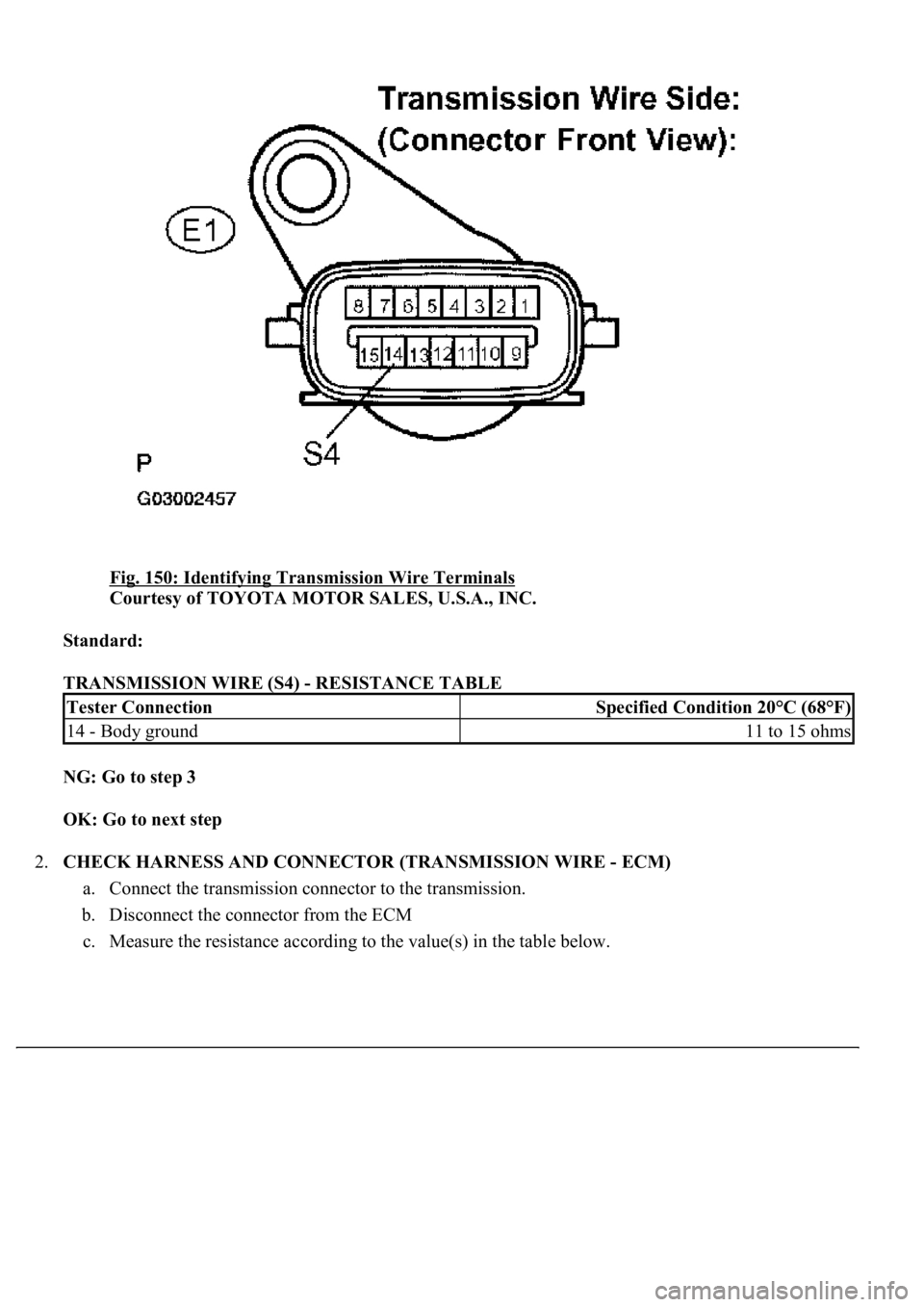
Fig. 150: Identifying Transmission Wire Terminals
Courtesy of TOYOTA MOTOR SALES, U.S.A., INC.
Standard:
TRANSMISSION WIRE (S4) - RESISTANCE TABLE
NG: Go to step 3
OK: Go to next step
2.CHECK HARNESS AND CONNECTOR (TRANSMISSION WIRE - ECM)
a. Connect the transmission connector to the transmission.
b. Disconnect the connector from the ECM
c. Measure the resistance accordin
g to the value(s) in the table below.
Tester ConnectionSpecified Condition 20°C (68°F)
14 - Body ground11 to 15 ohms
