LEXUS LS430 2003 Factory Service Manual
LS430 2003
LEXUS
LEXUS
https://www.carmanualsonline.info/img/36/57050/w960_57050-0.png
LEXUS LS430 2003 Factory Service Manual
Page 3984 of 4500
Fig. 45: Checking Operation Of Slide Motor
Courtesy of TOYOTA MOTOR SALES, U.S.A., INC.
b. Check operation of the vertical motor.
1. Check if the motor rotates smoothly when the battery is connected to the vertical motor
connector terminals.
OK:
MEASUREMENT CONDITION AND SPECIFIED CONDITION
Measurement ConditionSpecified Condition
Battery positive (+) --> 1 Battery negative (-) --> 2Counterclockwise
Page 3985 of 4500
If the result is not as specified, replace the vertical motor.
Fig. 46: Checking Operation Of Vertical Motor
Courtesy of TOYOTA MOTOR SALES, U.S.A., INC.
c. Check operation of the lifter motor.
1. Check if the motor rotates smoothly when the battery is connected to the lifter motor
connector terminals.
OK:
MEASUREMENT CONDITION AND SPECIFIED CONDITION
Battery positive (+) --> 2 Battery negative (-) --> 1Clockwise
Measurement ConditionSpecified Condition
Page 3986 of 4500
If the result is not as specified, replace the lifter motor.
Fig. 47: Checking Operation Of Lifter Motor
Courtesy of TOYOTA MOTOR SALES, U.S.A., INC.
d. Check operation of the reclining motor.
1. Check if the motor rotates smoothly when the battery is connected to the reclining motor
connector terminals.
OK:
MEASUREMENT CONDITION AND SPECIFIED CONDITION
Battery positive (+) --> 1 Battery negative (-) --> 2Counterclockwise
Battery positive (+) --> 2 Battery negative (-) --> 1Clockwise
Page 3987 of 4500
If the result is not as specified, replace the reclining motor.
Fig. 48: Checking Operation Of Reclining Motor
Courtesy of TOYOTA MOTOR SALES, U.S.A., INC.
e. Check operation of the cushion slide motor.
1. Check if the motor rotates smoothly when the battery is connected to the cushion slide motor
connector terminals.
Measurement ConditionSpecified Condition
Battery positive (+) --> 1 Battery negative (-) --> 2Counterclockwise
Battery positive (+) --> 2 Battery negative (-) --> 1Clockwise
Page 3988 of 4500
OK:
MEASUREMENT CONDITION AND SPECIFIED CONDITION
If the result is not as specified, replace the cushion slide motor.
Fig. 49: Checking Operation Of Cushion Slide Motor
Courtesy of TOYOTA MOTOR SALES, U.S.A., INC.
8.INSPECT POWER SEAT MOTOR (LUMBAR SUPPORT)
a. Check operation of the lumbar support adjuster motor.
1. Check if the motor rotates smoothl
y when the battery is connected to the lumbar support
Measurement ConditionSpecified Condition
Battery positive (+) --> 1 Battery negative (-) --> 2Counterclockwise
Battery positive (+) --> 2 Battery negative (-) --> 1Clockwise
Page 3989 of 4500
adjuster motor connector terminals.
OK:
MEASUREMENT CONDITION AND SPECIFIED CONDITION
If the result is not as specified, replace the adjuster motor.
Fig. 50: Checking Operation Of Lumbar Support Adjuster Motor
Courtesy of TOYOTA MOTOR SALES, U.S.A., INC.
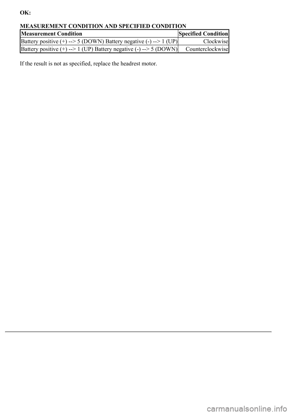
9.INSPECT POWER SEAT MOTOR (HEADREST)
a. Check operation of the headrest motor.
1. Check if the motor rotates smoothly when the battery is connected to the headrest motor
connector terminals.
Measurement ConditionSpecified Condition
Battery positive (+) --> 1 Battery negative (-) --> 2Clockwise
Battery positive (+) --> 2 Battery negative (-) --> 1Counterclockwise
Page 3990 of 4500
OK:
MEASUREMENT CONDITION AND SPECIFIED CONDITION
If the result is not as specified, replace the headrest motor.
Measurement ConditionSpecified Condition
Battery positive (+) --> 5 (DOWN) Battery negative (-) --> 1 (UP)Clockwise
Battery positive (+) --> 1 (UP) Battery negative (-) --> 5 (DOWN)Counterclockwise
Page 4009 of 4500
REPLACEMENT
HINT:
Use the same procedures for the RH side and LH side.
The procedures listed below are for the LH side.
1.REMOVE FRONT WHEELS
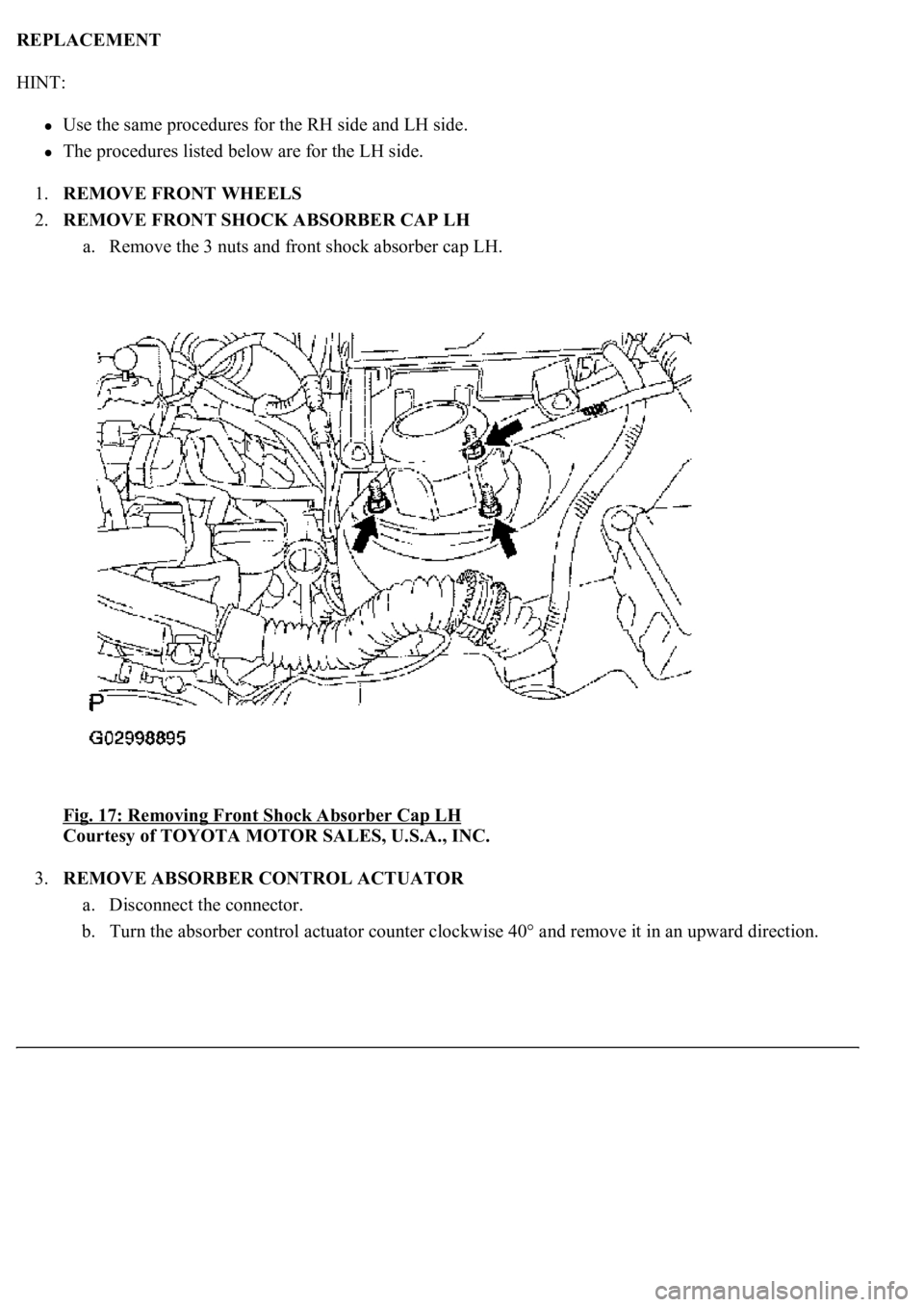
2.REMOVE FRONT SHOCK ABSORBER CAP LH
a. Remove the 3 nuts and front shock absorber cap LH.
Fig. 17: Removing Front Shock Absorber Cap LH
Courtesy of TOYOTA MOTOR SALES, U.S.A., INC.
3.REMOVE ABSORBER CONTROL ACTUATOR
a. Disconnect the connector.
b. Turn the absorber control actuator counter clockwise 40° and remove it in an upward direction.
Page 4020 of 4500
Fig. 28: Checking Rod Position
Courtesy of TOYOTA MOTOR SALES, U.S.A., INC.
b. Install the absorber control actuator to the pneumatic front LH w/shock absorber cylinder assy.
c. Until a response is felt, turn the absorber control actuator clockwise approx. 40°.
d. Connect the connector.
Page 4162 of 4500
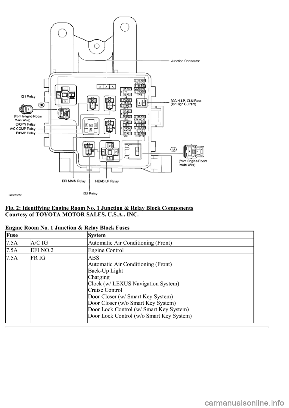
Fig. 2: Identifying Engine Room No. 1 Junction & Relay Block Components
Courtesy of TOYOTA MOTOR SALES, U.S.A., INC.
Engine Room No. 1 Junction & Relay Block Fuses
FuseSystem
7.5AA/C IGAutomatic Air Conditioning (Front)
7.5AEFI NO.2Engine Control
7.5AFR IGABS
Automatic Air Conditioning (Front)
Back-Up Light
Charging
Clock (w/ LEXUS Navigation System)
Cruise Control
Door Closer (w/ Smart Key System)
Door Closer (w/o Smart Key System)
Door Lock Control (w/ Smart Key System)
Door Lock Control (w/o Smart Key System)