air conditioning LEXUS LS430 2003 Factory Workshop Manual
[x] Cancel search | Manufacturer: LEXUS, Model Year: 2003, Model line: LS430, Model: LEXUS LS430 2003Pages: 4500, PDF Size: 87.45 MB
Page 321 of 4500

Fig. 92: Checking Harness And Connector (A/C Solar Sensor -Air Conditoning Amplifier)
Courtesy of TOYOTA MOTOR SALES, U.S.A., INC.
NG: REPAIR OR REPLACE HARNESS OR CONNECTOR
OK: REPLACE AIR CONDITIONING AMPLIFIER (SEE REPLACEMENT
)
CIRCUIT DESCRIPTION
This sensor detects the position of the air inlet servomotor and sends the appropriate signals to the A/C
amplifier. The position sensor is built in the air inlet servomotor.
<0029004c004a00110003001c0016001d000300370033002c00030037004800550050004c00510044004f000300390052004f00570044004a0048000300270044005000530048005500030032005300480051004c0051004a000300240051004a004f004800
03002a005500440053004b[
Courtesy of TOYOTA MOTOR SALES, U.S.A., INC.
Page 323 of 4500
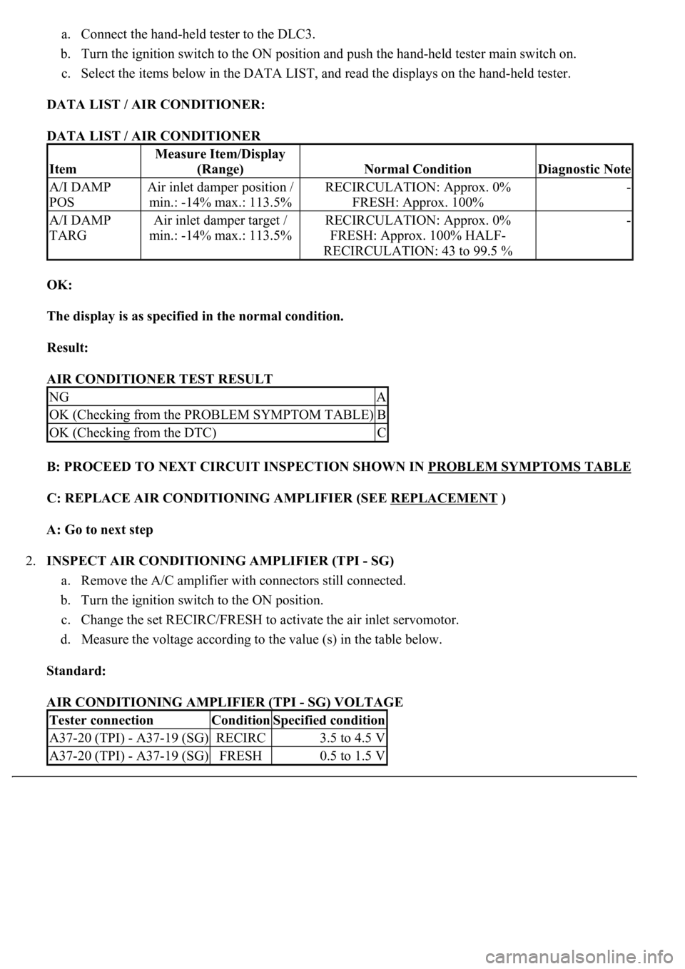
a. Connect the hand-held tester to the DLC3.
b. Turn the ignition switch to the ON position and push the hand-held tester main switch on.
c. Select the items below in the DATA LIST, and read the displays on the hand-held tester.
DATA LIST / AIR CONDITIONER:
DATA LIST / AIR CONDITIONER
OK:
The display is as specified in the normal condition.
Result:
AIR CONDITIONER TEST RESULT
B: PROCEED TO NEXT CIRCUIT INSPECTION SHOWN IN PROBLEM SYMPTOMS TABLE
C: REPLACE AIR CONDITIONING AMPLIFIER (SEE REPLACEMENT )
A: Go to next step
2.INSPECT AIR CONDITIONING AMPLIFIER (TPI - SG)
a. Remove the A/C amplifier with connectors still connected.
b. Turn the ignition switch to the ON position.
c. Change the set RECIRC/FRESH to activate the air inlet servomotor.
d. Measure the voltage according to the value (s) in the table below.
Standard:
AIR CONDITIONING AMPLIFIER (TPI - SG) VOLTAGE
Item
Measure Item/Display
(Range)
Normal ConditionDiagnostic Note
A/I DAMP
POSAir inlet damper position /
min.: -14% max.: 113.5%RECIRCULATION: Approx. 0%
FRESH: Approx. 100%-
A/I DAMP
TARGAir inlet damper target /
min.: -14% max.: 113.5%RECIRCULATION: Approx. 0%
FRESH: Approx. 100% HALF-
RECIRCULATION: 43 to 99.5 %-
NGA
OK (Checking from the PROBLEM SYMPTOM TABLE)B
OK (Checking from the DTC)C
Tester connectionConditionSpecified condition
A37-20 (TPI) - A37-19 (SG)RECIRC3.5 to 4.5 V
A37-20 (TPI) - A37-19 (SG)FRESH0.5 to 1.5 V
Page 324 of 4500

HINT:
As the air inlet servomotor moves from the RECIRC side to the FRESH side, the voltage decreases
gradually without interruption.
Result:
AIR CONDITIONING AMPLIFIER (TPI - SG) TEST RESULT
<0029004c004a00110003001c0019001d0003002c005100560053004800460057004c0051004a00030024004c005500030026005200510047004c0057004c00520051004c0051004a0003002400500053004f004c0049004c004800550003000b0037003300
2c0003[
- SG)
Courtesy of TOYOTA MOTOR SALES, U.S.A., INC.
B: PROCEED TO NEXT CIRCUIT INSPECTION SHOWN IN PROBLEM SYMPTOMS TABLE
C: REPLACE AIR CONDITIONING AMPLIFIER (SEE REPLACEMENT )
A: Go to next step
3.INSPECT AIR INLET SERVOMOTOR
NGA
OK (Checking from the PROBLEM SYMPTOMS TABLE)B
OK (Checking from the DTC)C
Page 326 of 4500

Fig. 97: Inspecting Air Inlet Servomotor
Courtesy of TOYOTA MOTOR SALES, U.S.A., INC.
NG: REPLACE AIR INLET SERVOMOTOR
OK: Go to next step
4.CHECK HARNESS AND CONNECTOR (AIR INLET SERVOMOTOR - AIR CONDITIONING
AMPLIFIER) (SEE ELECTRONIC CIRCUIT INSPECTION PROCEDURE
)
a. Measure the resistance according to the value (s) in the table below.
Standard:
AIR INLET SERVOMOTOR - AIR CONDITIONING AMPLIFIER RESISTANCE
Tester connectionConditionSpecified condition
A37-20 (TPI) - A41-3 (PT)AlwaysBelow 1 ohms
A37-18 (S5-3) - A41-1 (VZ)AlwaysBelow 1 ohms
A37-19 (SG) - A41-2 (GND)AlwaysBelow 1 ohms
A37-20 (TPI) - Body groundAlways10 kohms or higher
A37-18 (S5-3) - Body groundAlways10 kohms or higher
Page 328 of 4500

Fig. 98: Checking Harness And Connector (Air Inlet Servomotor - Air Conditioning Amplifier)
Page 329 of 4500

Courtesy of TOYOTA MOTOR SALES, U.S.A., INC.
NG: REPAIR OR REPLACE HARNESS OR CONNECTOR
OK: REPLACE AIR CONDITIONING AMPLIFIER (SEE REPLACEMENT
)
CIRCUIT DESCRIPTION
This sensor detects the position of the cool air bypass servomotor (Max cool damper servomotor) and sends the
appropriate signals to the A/C amplifier. The position sensor is built in the cool air bypass servomotor.
Page 331 of 4500
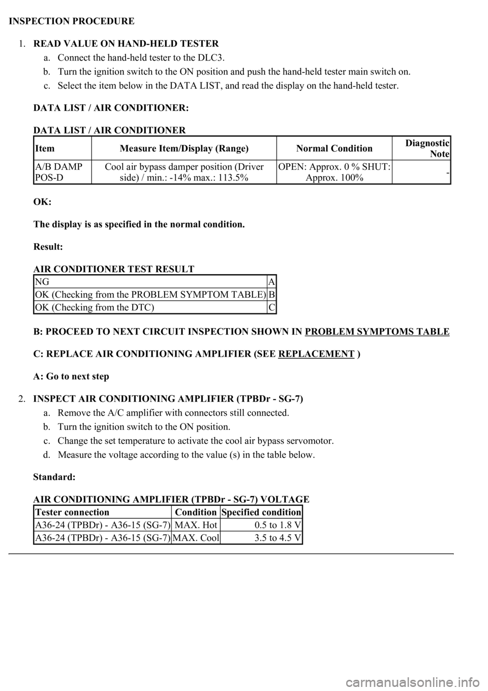
INSPECTION PROCEDURE
1.READ VALUE ON HAND-HELD TESTER
a. Connect the hand-held tester to the DLC3.
b. Turn the ignition switch to the ON position and push the hand-held tester main switch on.
c. Select the item below in the DATA LIST, and read the display on the hand-held tester.
DATA LIST / AIR CONDITIONER:
DATA LIST / AIR CONDITIONER
OK:
The display is as specified in the normal condition.
Result:
AIR CONDITIONER TEST RESULT
B: PROCEED TO NEXT CIRCUIT INSPECTION SHOWN IN PROBLEM SYMPTOMS TABLE
C: REPLACE AIR CONDITIONING AMPLIFIER (SEE REPLACEMENT )
A: Go to next step
2.INSPECT AIR CONDITIONING AMPLIFIER (TPBDr - SG-7)
a. Remove the A/C amplifier with connectors still connected.
b. Turn the ignition switch to the ON position.
c. Change the set temperature to activate the cool air bypass servomotor.
d. Measure the voltage according to the value (s) in the table below.
Standard:
AIR CONDITIONING AMPLIFIER (TPBDr - SG-7) VOLTAGE
ItemMeasure Item/Display (Range)Normal ConditionDiagnostic
Note
A/B DAMP
POS-DCool air bypass damper position (Driver
side) / min.: -14% max.: 113.5%OPEN: Approx. 0 % SHUT:
Approx. 100%-
NGA
OK (Checking from the PROBLEM SYMPTOM TABLE)B
OK (Checking from the DTC)C
Tester connectionConditionSpecified condition
A36-24 (TPBDr) - A36-15 (SG-7)MAX. Hot0.5 to 1.8 V
A36-24 (TPBDr) - A36-15 (SG-7)MAX. Cool3.5 to 4.5 V
Page 332 of 4500

HINT:
As the set temperature increases, the voltage decreases gradually without interruption.
Result:
AIR CONDITIONING AMPLIFIER (TPBDR - SG-7) TEST RESULT
Fig. 102: Inspecting Air Conditioning Amplifier (TPBDR
- SG-7)
Courtesy of TOYOTA MOTOR SALES, U.S.A., INC.
B: PROCEED TO NEXT CIRCUIT INSPECTION SHOWN IN PROBLEM SYMPTOMS TABLE
C: REPLACE AIR CONDITIONING AMPLIFIER (SEE REPLACEMENT )
A: Go to next step
3.INSPECT COOL AIR BYPASS SERVOMOTOR
NGA
OK (Checking from the PROBLEM SYMPTOMS TABLE)B
OK (Checking from the DTC)C
Page 334 of 4500

Fig. 103: Inspecting Cool Air Bypass Servomotor
Courtesy of TOYOTA MOTOR SALES, U.S.A., INC.
NG: REPLACE COOL AIR BYPASS SERVOMOTOR
OK: Go to next step
4.CHECK HARNESS AND CONNECTOR (COOL AIR BYPASS SERVOMOTOR - AIR
CONDITIONING AMPLIFIER) (SEE ELECTRONIC CIRCUIT INSPECTION PROCEDURE
)
a. Measure the resistance according to the value (s) in the table below.
Standard:
COOL AIR BYPASS SERVOMOTOR - AIR CONDITIONING AMPLIFIER RESISTANCE
Tester connectionConditionSpecified condition
A36-24 (TPBDr) - C24-3 (PT)AlwaysBelow 1 ohms
A36-11 (S5-5) - C24-1 (VZ)AlwaysBelow 1 ohms
A36-15 (SG-7) - C24-2 (GND)AlwaysBelow 1 ohms
C24-3 (PT) - Body groundAlways10 kohms or higher
C24-1 (VZ) - Body groundAlways10 kohms or higher
Page 337 of 4500

Fig. 104: Checking Harness And Connector (Cool Air Bypass Servomotor - Air Conditioning
Amplifier)
Courtesy of TOYOTA MOTOR SALES, U.S.A., INC.
NG: REPAIR OR REPLACE HARNESS OR CONNECTOR
OK: REPLACE AIR CONDITIONING AMPLIFIER (SEE REPLACEMENT
)
CIRCUIT DESCRIPTION
This sensor detects the position of the cool air bypass servomotor (Max cool damper servomotor) and sends the
appropriate si
gnals to the A/C amplifier. The position sensor is built in the cool air bypass servomotor.