ECU LEXUS LS430 2003 Factory Repair Manual
[x] Cancel search | Manufacturer: LEXUS, Model Year: 2003, Model line: LS430, Model: LEXUS LS430 2003Pages: 4500, PDF Size: 87.45 MB
Page 4090 of 4500

3.CHECK WIRE HARNESS (DRIVER SIDE J/B ECU - FUEL LID OPENER SWITCH AND
BODY GROUND)
a. Disconnect the D6 ECU connector.
b. Disconnect the F12 switch connector.
c. Measure the resistance of the wire harness side connectors.
Standard:
TESTER CONNECTION AND SPECIFIED CONDITION
Tester connectionSpecified condition
D6-4 (FUEL) - F12-2Below 1 ohms
F12-1 - Body groundBelow 1 ohms
Page 4091 of 4500
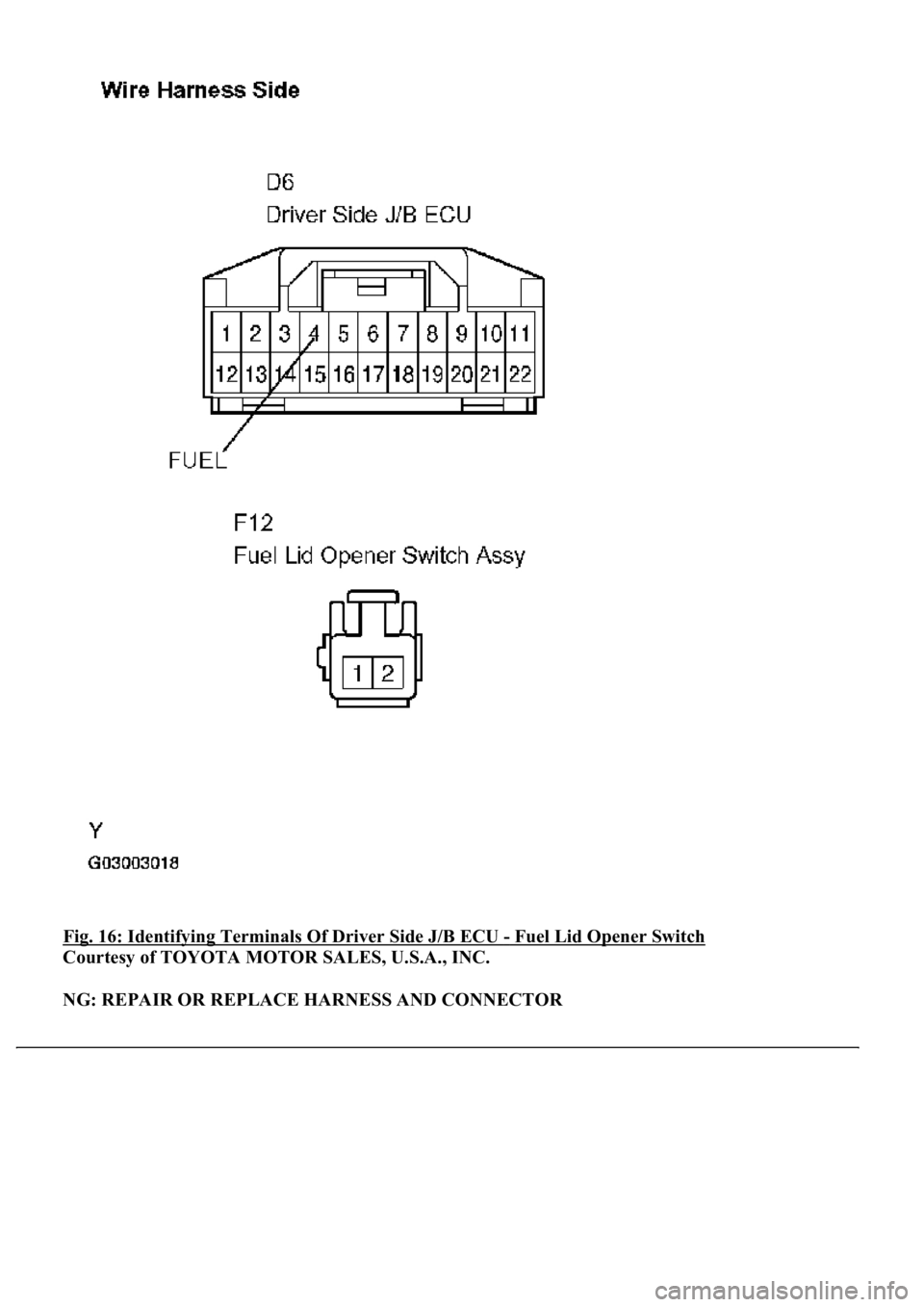
Fig. 16: Identifying Terminals Of Driver Side J/B ECU - Fuel Lid Opener Switch
Courtesy of TOYOTA MOTOR SALES, U.S.A., INC.
NG: REPAIR OR REPLACE HARNESS AND CONNECTOR
Page 4092 of 4500
OK: PROCEED TO NEXT CIRCUIT INSPECTION SHOWN ON PROBLEM SYMPTOMS
TABLE
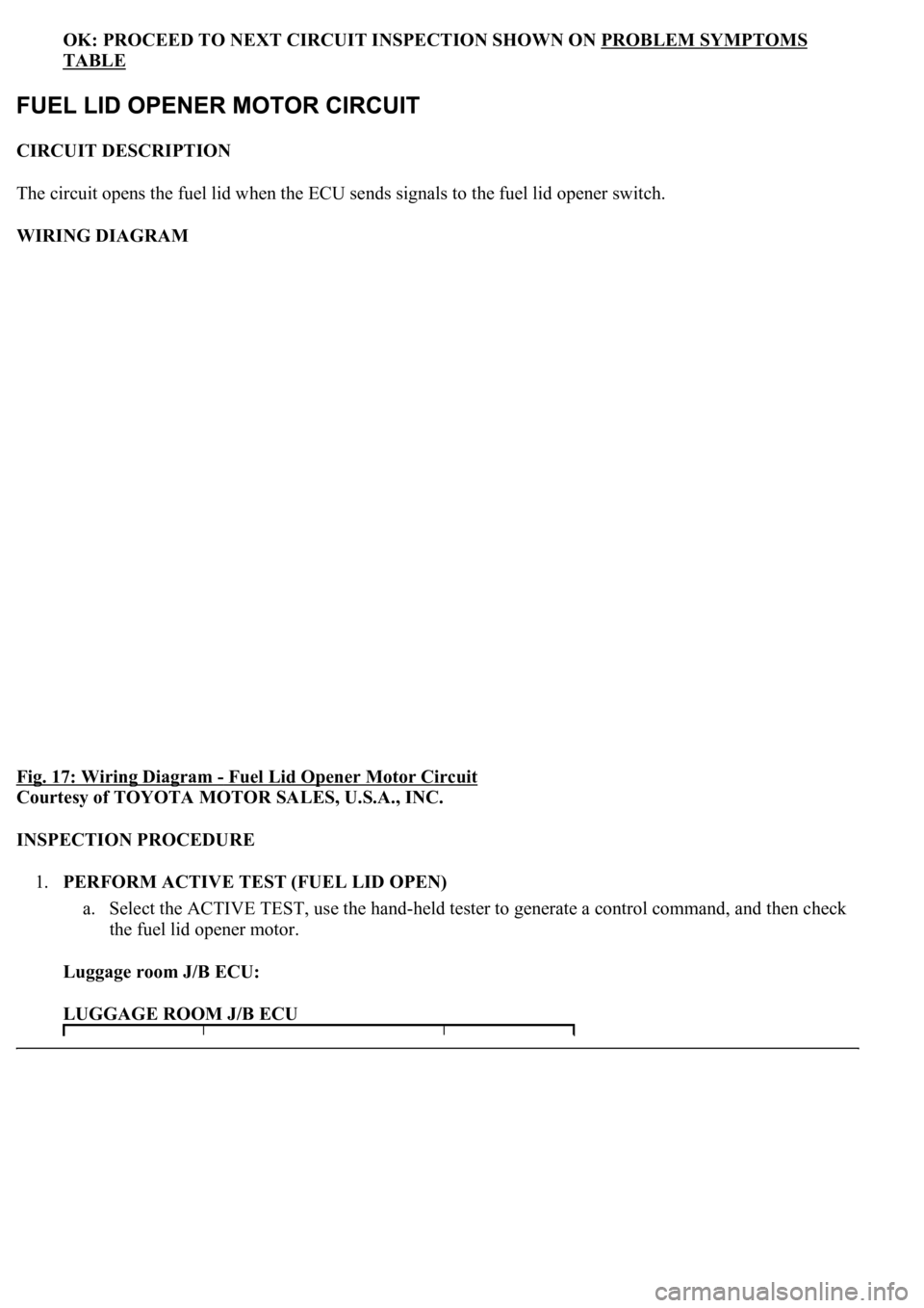
CIRCUIT DESCRIPTION
The circuit opens the fuel lid when the ECU sends signals to the fuel lid opener switch.
WIRING DIAGRAM
Fig. 17: Wiring Diagram
- Fuel Lid Opener Motor Circuit
Courtesy of TOYOTA MOTOR SALES, U.S.A., INC.
INSPECTION PROCEDURE
1.PERFORM ACTIVE TEST (FUEL LID OPEN)
a. Select the ACTIVE TEST, use the hand-held tester to generate a control command, and then check
the fuel lid opener motor.
Luggage room J/B ECU:
LUGGAGE ROOM J/B ECU
Page 4110 of 4500
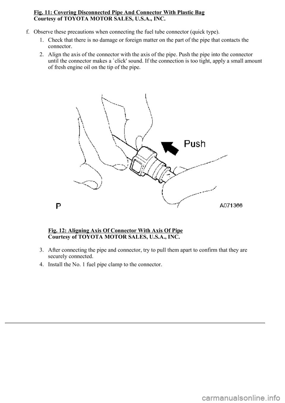
Fig. 11: Covering Disconnected Pipe And Connector With Plastic Bag
Courtesy of TOYOTA MOTOR SALES, U.S.A., INC.
f. Observe these precautions when connecting the fuel tube connector (quick type).
1. Check that there is no damage or foreign matter on the part of the pipe that contacts the
connector.
2. Align the axis of the connector with the axis of the pipe. Push the pipe into the connector
until the connector makes a `click' sound. If the connection is too tight, apply a small amount
of fresh engine oil on the tip of the pipe.
Fig. 12: Aligning Axis Of Connector With Axis Of Pipe
Courtesy of TOYOTA MOTOR SALES, U.S.A., INC.
3. After connecting the pipe and connector, try to pull them apart to confirm that they are
securely connected.
4. Install the No. 1 fuel pipe clamp to the connector.
Page 4172 of 4500
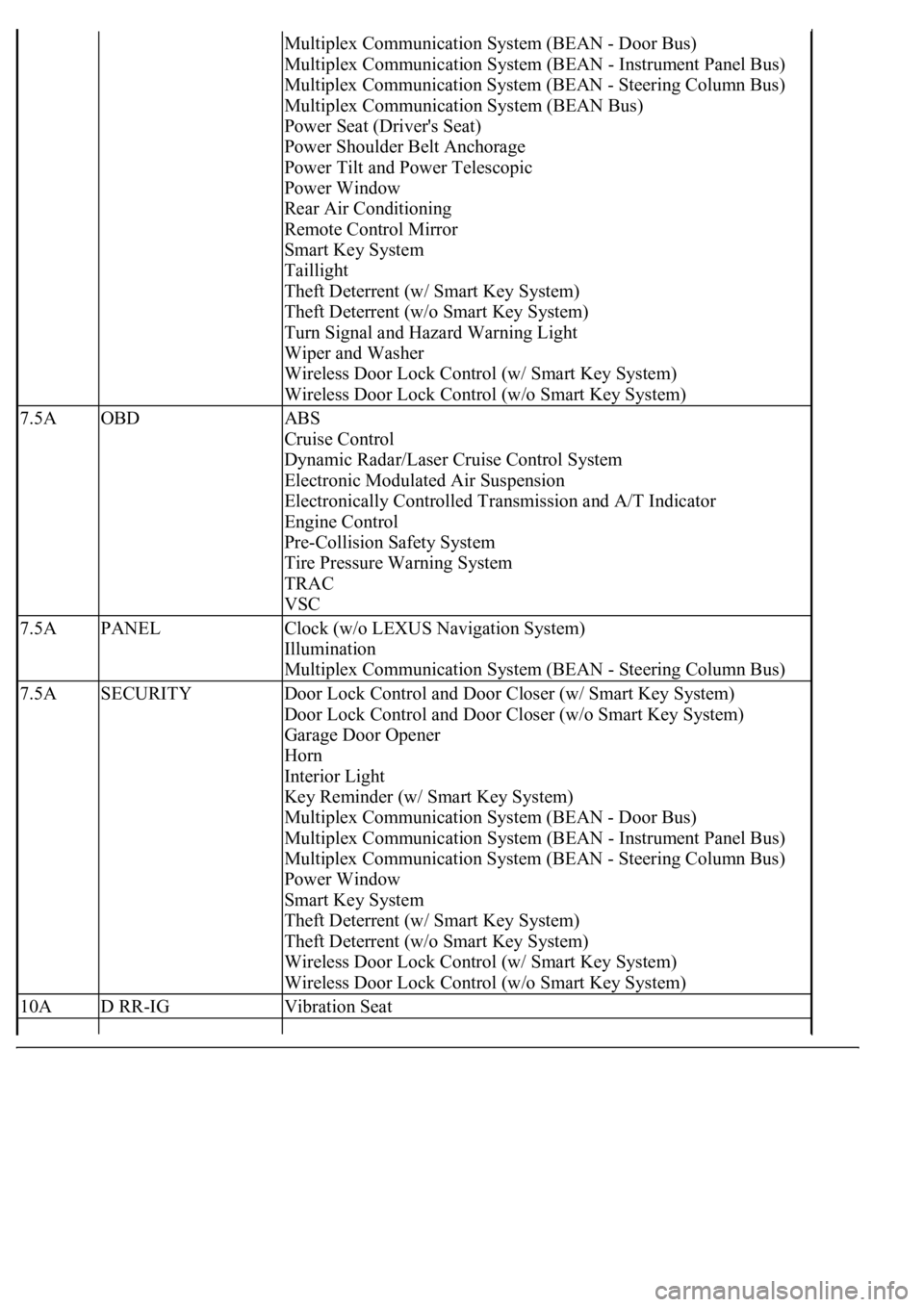
Multiplex Communication System (BEAN - Door Bus)
Multiplex Communication System (BEAN - Instrument Panel Bus)
Multiplex Communication System (BEAN - Steering Column Bus)
Multiplex Communication System (BEAN Bus)
Power Seat (Driver's Seat)
Power Shoulder Belt Anchorage
Power Tilt and Power Telescopic
Power Window
Rear Air Conditioning
Remote Control Mirror
Smart Key System
Taillight
Theft Deterrent (w/ Smart Key System)
Theft Deterrent (w/o Smart Key System)
Turn Signal and Hazard Warning Light
Wiper and Washer
Wireless Door Lock Control (w/ Smart Key System)
Wireless Door Lock Control (w/o Smart Key System)
7.5AOBDABS
Cruise Control
Dynamic Radar/Laser Cruise Control System
Electronic Modulated Air Suspension
Electronically Controlled Transmission and A/T Indicator
Engine Control
Pre-Collision Safety System
Tire Pressure Warning System
TRAC
VSC
7.5APANELClock (w/o LEXUS Navigation System)
Illumination
Multiplex Communication System (BEAN - Steering Column Bus)
7.5ASECURITYDoor Lock Control and Door Closer (w/ Smart Key System)
Door Lock Control and Door Closer (w/o Smart Key System)
Garage Door Opener
Horn
Interior Light
Key Reminder (w/ Smart Key System)
Multiplex Communication System (BEAN - Door Bus)
Multiplex Communication System (BEAN - Instrument Panel Bus)
Multiplex Communication System (BEAN - Steering Column Bus)
Power Window
Smart Key System
Theft Deterrent (w/ Smart Key System)
Theft Deterrent (w/o Smart Key System)
Wireless Door Lock Control (w/ Smart Key System)
Wireless Door Lock Control (w/o Smart Key System)
10AD RR-IGVibration Seat
Page 4182 of 4500
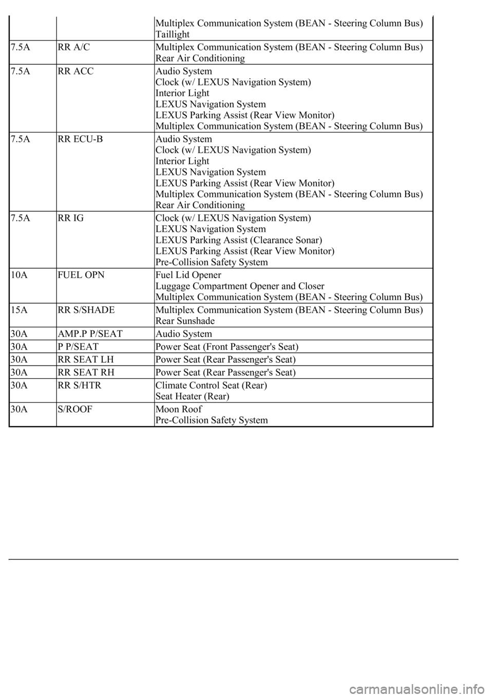
Multiplex Communication System (BEAN - Steering Column Bus)
Taillight
7.5ARR A/CMultiplex Communication System (BEAN - Steering Column Bus)
Rear Air Conditioning
7.5ARR ACCAudio System
Clock (w/ LEXUS Navigation System)
Interior Light
LEXUS Navigation System
LEXUS Parking Assist (Rear View Monitor)
Multiplex Communication System (BEAN - Steering Column Bus)
7.5ARR ECU-BAudio System
Clock (w/ LEXUS Navigation System)
Interior Light
LEXUS Navigation System
LEXUS Parking Assist (Rear View Monitor)
Multiplex Communication System (BEAN - Steering Column Bus)
Rear Air Conditioning
7.5ARR IGClock (w/ LEXUS Navigation System)
LEXUS Navigation System
LEXUS Parking Assist (Clearance Sonar)
LEXUS Parking Assist (Rear View Monitor)
Pre-Collision Safety System
10AFUEL OPNFuel Lid Opener
Luggage Compartment Opener and Closer
Multiplex Communication System (BEAN - Steering Column Bus)
15ARR S/SHADEMultiplex Communication System (BEAN - Steering Column Bus)
Rear Sunshade
30AAMP.P P/SEATAudio System
30AP P/SEATPower Seat (Front Passenger's Seat)
30ARR SEAT LHPower Seat (Rear Passenger's Seat)
30ARR SEAT RHPower Seat (Rear Passenger's Seat)
30ARR S/HTRClimate Control Seat (Rear)
Seat Heater (Rear)
30AS/ROOFMoon Roof
Pre-Collision Safety System
Page 4184 of 4500
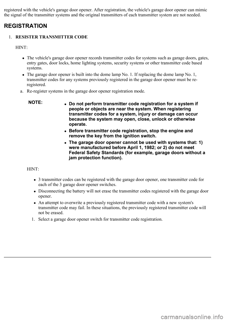
registered with the vehicle's garage door opener. After registration, the vehicle's garage door opener can mimic
the signal of the transmitter systems and the original transmitters of each transmitter system are not needed.
1.RESISTER TRANSMITTER CODE
HINT:
The vehicle's garage door opener records transmitter codes for systems such as garage doors, gates,
entry gates, door locks, home lighting systems, security systems or other transmitter code based
systems.
The garage door opener is built into the dome lamp No. 1. If replacing the dome lamp No. 1,
transmitter codes for any systems previously registered in the garage door opener must be re-
registered.
a. Re-register systems in the garage door opener registration mode.
HINT:
3 transmitter codes can be registered with the garage door opener, one transmitter code for
each of the 3 garage door opener switches.
Disconnecting the battery will not erase the transmitter codes registered with the garage door
opener.
An attempt to overwrite a previously registered transmitter code with a new system's
transmitter code may fail. In these situations, the previously registered transmitter code will
not be erased.
1. Select a
garage door opener switch for transmitter code registration.
Page 4210 of 4500
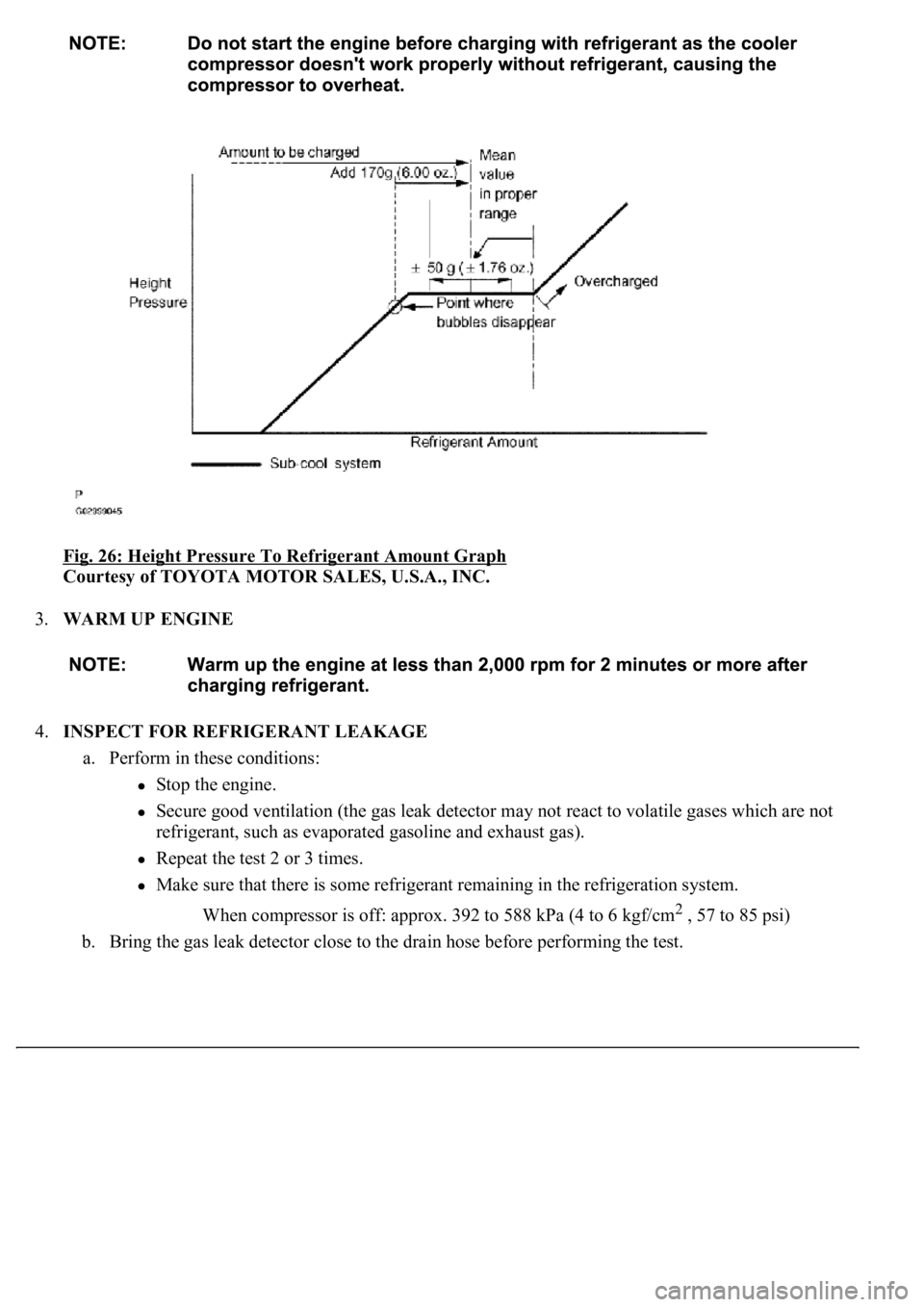
Fig. 26: Height Pressure To Refrigerant Amount Graph
Courtesy of TOYOTA MOTOR SALES, U.S.A., INC.
3.WARM UP ENGINE
4.INSPECT FOR REFRIGERANT LEAKAGE
a. Perform in these conditions:
Stop the engine.
Secure good ventilation (the gas leak detector may not react to volatile gases which are not
refrigerant, such as evaporated gasoline and exhaust gas).
Repeat the test 2 or 3 times.
Make sure that there is some refrigerant remaining in the refrigeration system.
When compressor is off: approx. 392 to 588 kPa (4 to 6 kgf/cm
2 , 57 to 85 psi)
b. Bring the gas leak detector close to the drain hose before performing the test.
Page 4258 of 4500
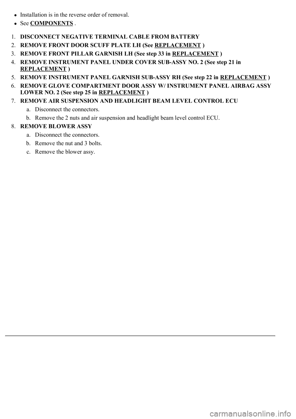
Installation is in the reverse order of removal.
See COMPONENTS .
1.DISCONNECT NEGATIVE TERMINAL CABLE FROM BATTERY
2.REMOVE FRONT DOOR SCUFF PLATE LH (See REPLACEMENT
)
3.REMOVE FRONT PILLAR GARNISH LH (See step 33 in REPLACEMENT
)
4.REMOVE INSTRUMENT PANEL UNDER COVER SUB-ASSY NO. 2 (See step 21 in
REPLACEMENT
)
5.REMOVE INSTRUMENT PANEL GARNISH SUB-ASSY RH (See step 22 in REPLACEMENT
)
6.REMOVE GLOVE COMPARTMENT DOOR ASSY W/ INSTRUMENT PANEL AIRBAG ASSY
LOWER NO. 2 (See step 25 in REPLACEMENT
)
7.REMOVE AIR SUSPENSION AND HEADLIGHT BEAM LEVEL CONTROL ECU
a. Disconnect the connectors.
b. Remove the 2 nuts and air suspension and headlight beam level control ECU.
8.REMOVE BLOWER ASSY
a. Disconnect the connectors.
b. Remove the nut and 3 bolts.
c. Remove the blower assy.
Page 4379 of 4500

Fig. 31: Removing Heater To Register Duct Assy
Courtesy of TOYOTA MOTOR SALES, U.S.A., INC.
54.REMOVE NETWORK GATEWAY ECU
a. Remove the 2 screws < N > and network gateway ECU.
55.REMOVE HEATER TO REGISTER DUCT NO.2
a. Remove the 2 screws < N > and the heater to register duct No.2.