Air Conditioning Compressor LEXUS LS430 2003 Factory Repair Manual
[x] Cancel search | Manufacturer: LEXUS, Model Year: 2003, Model line: LS430, Model: LEXUS LS430 2003Pages: 4500, PDF Size: 87.45 MB
Page 210 of 4500
Fig. 6: Air Conditioning System Diagram (2 Of 2)
Courtesy of TOYOTA MOTOR SALES, U.S.A., INC.
1.GENERAL
a. The air conditioning system has the following features:
In compliance with the temperature set at the temperature control switch, the neural network
control calculates the outlet temperature based on the input signals from various sensors. In
addition, corrections in accordance with the signals from the evaporative temperature sensor
and the water temperature sensor are added to control the outlet air temperature.
Controls the front and rear blower motors in accordance with the airflow volume that has
been calculated by the neural network control based on the input signals from various
sensors.
Automatically switches the outlets in accordance with the outlet mode ratio that has been
calculated by the neural network control based on the input signals from various sensors.
Automatically controls the air inlet control damper in accordance with the airflow volume
that has been calculated by the neural network control.
Turns the compressor on/off and controls the discharge capacity based on the signals from
various sensors.
Based on the signals from the ambient temperature sensor, this control calculates the outside
temperature, which is then corrected in the air conditioner ECU, and shown in the multi-
information display in the combination meter.
Switched the rear defogger and outside rear view mirror heaters on for 15 minutes when the
rear defogger switch is switched on. Switched them off if the switch is pressed while they are
operating.
Controls the orientation and the angle of the front center register based on the input signals
from various sensors and on the outlet mode.
Determines whether the clean air filter (for the front A/C) is clogged by monitoring the air
inlets, and airflow volume.
The A/C amplifier automatically controls the air inlets based on the signals from the smog
ventilation sensor.
Improves the air quality by linking the air inlet control damper and the blower motor (for the
rear A/C and air purifier), based on the signals from the exhaust gas sensor and the smoke
sensor.
Checks the sensors in accordance with operation of the air conditioner switches.
2.MODEL POSITION AND DAMPER OPERATION
Page 230 of 4500
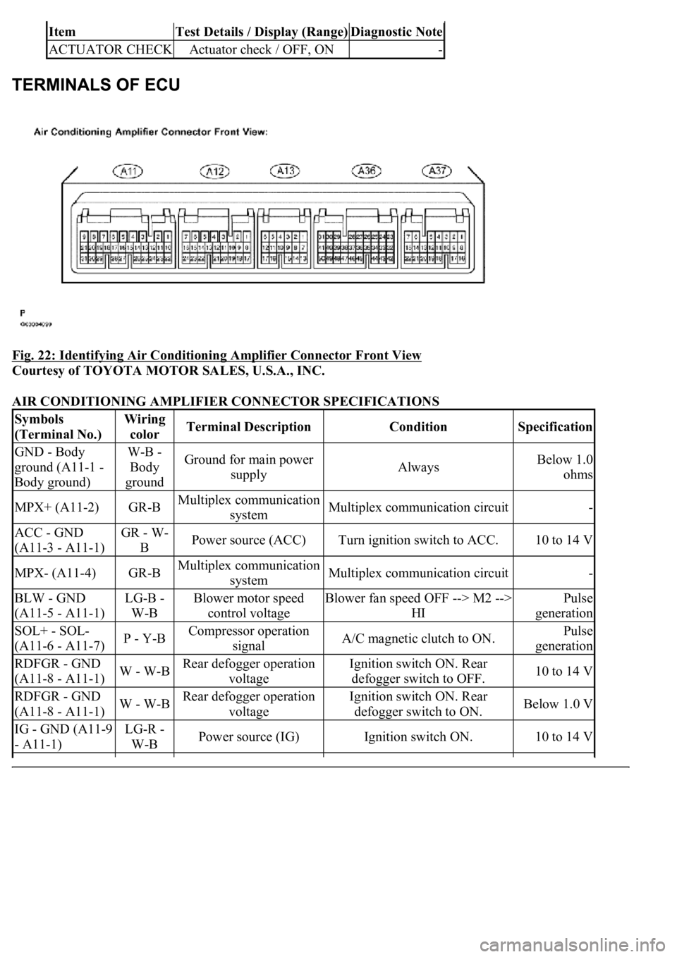
Fig. 22: Identifying Air Conditioning Amplifier Connector Front View
Courtesy of TOYOTA MOTOR SALES, U.S.A., INC.
AIR CONDITIONING AMPLIFIER CONNECTOR SPECIFICATIONS
ItemTest Details / Display (Range)Diagnostic Note
ACTUATOR CHECKActuator check / OFF, ON-
Symbols
(Terminal No.)Wiring
colorTerminal DescriptionConditionSpecification
GND - Body
ground (A11-1 -
Body ground)W-B -
Body
groundGround for main power
supplyAlwaysBelow 1.0
ohms
MPX+ (A11-2)GR-BMultiplex communication
systemMultiplex communication circuit-
ACC - GND
(A11-3 - A11-1)GR - W-
BPower source (ACC)Turn ignition switch to ACC.10 to 14 V
MPX- (A11-4)GR-BMultiplex communication
systemMultiplex communication circuit-
BLW - GND
(A11-5 - A11-1)LG-B -
W-BBlower motor speed
control voltageBlower fan speed OFF --> M2 -->
HIPulse
generation
SOL+ - SOL-
(A11-6 - A11-7)P - Y-BCompressor operation
signalA/C magnetic clutch to ON.Pulse
generation
RDFGR - GND
(A11-8 - A11-1)W - W-BRear defogger operation
voltageIgnition switch ON. Rear
defogger switch to OFF.10 to 14 V
RDFGR - GND
(A11-8 - A11-1)W - W-BRear defogger operation
voltageIgnition switch ON. Rear
defogger switch to ON.Below 1.0 V
IG - GND (A11-9
- A11-1)LG-R -
W-BPower source (IG)Ignition switch ON.10 to 14 V
Page 241 of 4500
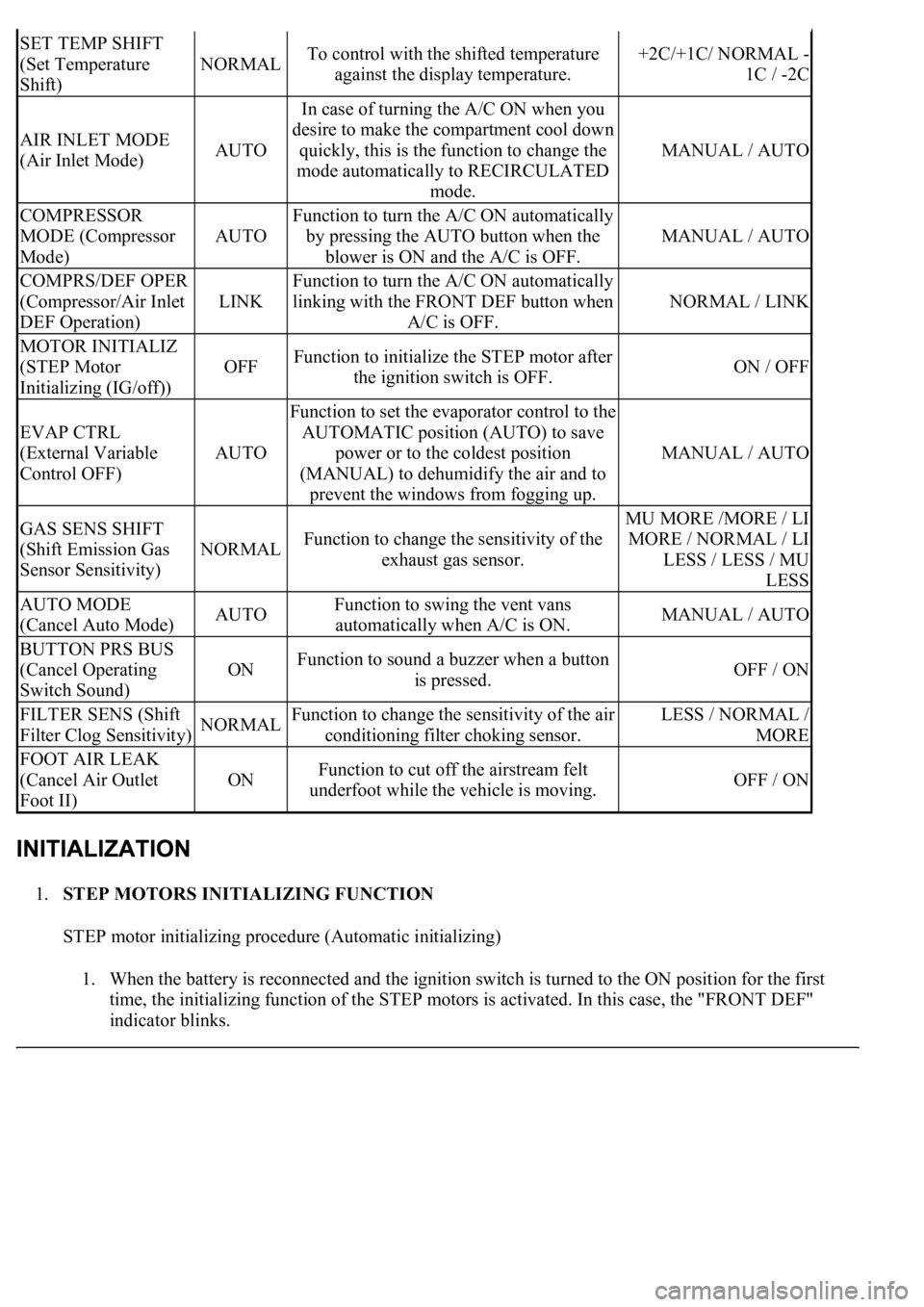
1.STEP MOTORS INITIALIZING FUNCTION
STEP motor initializing procedure (Automatic initializing)
1. When the battery is reconnected and the ignition switch is turned to the ON position for the first
time, the initializing function of the STEP motors is activated. In this case, the "FRONT DEF"
indicator blinks.
SET TEMP SHIFT
(Set Temperature
Shift)
NORMALTo control with the shifted temperature
against the display temperature.+2C/+1C/ NORMAL -
1C / -2C
AIR INLET MODE
(Air Inlet Mode)AUTO
In case of turning the A/C ON when you
desire to make the compartment cool down
quickly, this is the function to change the
mode automatically to RECIRCULATED
mode.
MANUAL / AUTO
COMPRESSOR
MODE (Compressor
Mode)
AUTO
Function to turn the A/C ON automatically
by pressing the AUTO button when the
blower is ON and the A/C is OFF.
MANUAL / AUTO
COMPRS/DEF OPER
(Compressor/Air Inlet
DEF Operation)
LINK
Function to turn the A/C ON automatically
linking with the FRONT DEF button when
A/C is OFF.
NORMAL / LINK
MOTOR INITIALIZ
(STEP Motor
Initializing (IG/off))
OFFFunction to initialize the STEP motor after
the ignition switch is OFF.ON / OFF
EVAP CTRL
(External Variable
Control OFF)
AUTO
Function to set the evaporator control to the
AUTOMATIC position (AUTO) to save
power or to the coldest position
(MANUAL) to dehumidify the air and to
prevent the windows from fogging up.
MANUAL / AUTO
GAS SENS SHIFT
(Shift Emission Gas
Sensor Sensitivity)
NORMALFunction to change the sensitivity of the
exhaust gas sensor.
MU MORE /MORE / LI
MORE / NORMAL / LI
LESS / LESS / MU
LESS
AUTO MODE
(Cancel Auto Mode)AUTOFunction to swing the vent vans
automatically when A/C is ON.MANUAL / AUTO
BUTTON PRS BUS
(Cancel Operating
Switch Sound)
ONFunction to sound a buzzer when a button
is pressed.OFF / ON
FILTER SENS (Shift
Filter Clog Sensitivity)NORMALFunction to change the sensitivity of the air
conditioning filter choking sensor.LESS / NORMAL /
MORE
FOOT AIR LEAK
(Cancel Air Outlet
Foot II)
ONFunction to cut off the airstream felt
underfoot while the vehicle is moving.OFF / ON
Page 298 of 4500

Courtesy of TOYOTA MOTOR SALES, U.S.A., INC.
NG: REPAIR OR REPLACE HARNESS OR CONNECTOR
OK: REPLACE AIR CONDITIONING AMPLIFIER (SEE REPLACEMENT
)
CIRCUIT DESCRIPTION
The pressure switch sends the appropriate signals to the A/C amplifier when the A/C refrigerant pressure drops
too low or rises too high.
When the A/C amplifier receives these signals, the compressor does not compress refrigerant.
Fig. 75: DTC Detection Item Trouble Area Chart
Courtesy of TOYOTA MOTOR SALES, U.S.A., INC.
WIRING DIAGRAM
Page 351 of 4500

NG: REPAIR OR REPLACE HARNESS OR CONNECTOR
OK: REPLACE AIR CONDITIONING AMPLIFIER (SEE REPLACEMENT )
CIRCUIT DESCRIPTION
In this circuit, the compressor assembly receives a signal on refrigerant compression required by the air
conditioning amplifier. Based on the signal, the compressor assembly changes the degree of refrigerant
compression.
Fig. 116: DTC Detection Item Trouble Area Chart
Courtesy of TOYOTA MOTOR SALES, U.S.A., INC.
WIRING DIAGRAM
Fig. 117: Compressor Solenoid Circuit
Page 353 of 4500
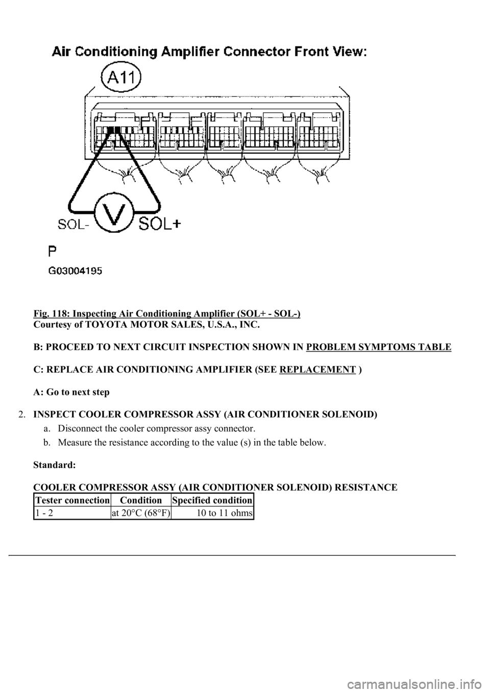
Fig. 118: Inspecting Air Conditioning Amplifier (SOL+ - SOL-)
Courtesy of TOYOTA MOTOR SALES, U.S.A., INC.
B: PROCEED TO NEXT CIRCUIT INSPECTION SHOWN IN PROBLEM SYMPTOMS TABLE
C: REPLACE AIR CONDITIONING AMPLIFIER (SEE REPLACEMENT )
A: Go to next step
2.INSPECT COOLER COMPRESSOR ASSY (AIR CONDITIONER SOLENOID)
a. Disconnect the cooler compressor assy connector.
b. Measure the resistance according to the value (s) in the table below.
Standard:
COOLER COMPRESSOR ASSY (AIR CONDITIONER SOLENOID) RESISTANCE
Tester connectionConditionSpecified condition
1 - 2at 20°C (68°F)10 to 11 ohms
Page 354 of 4500
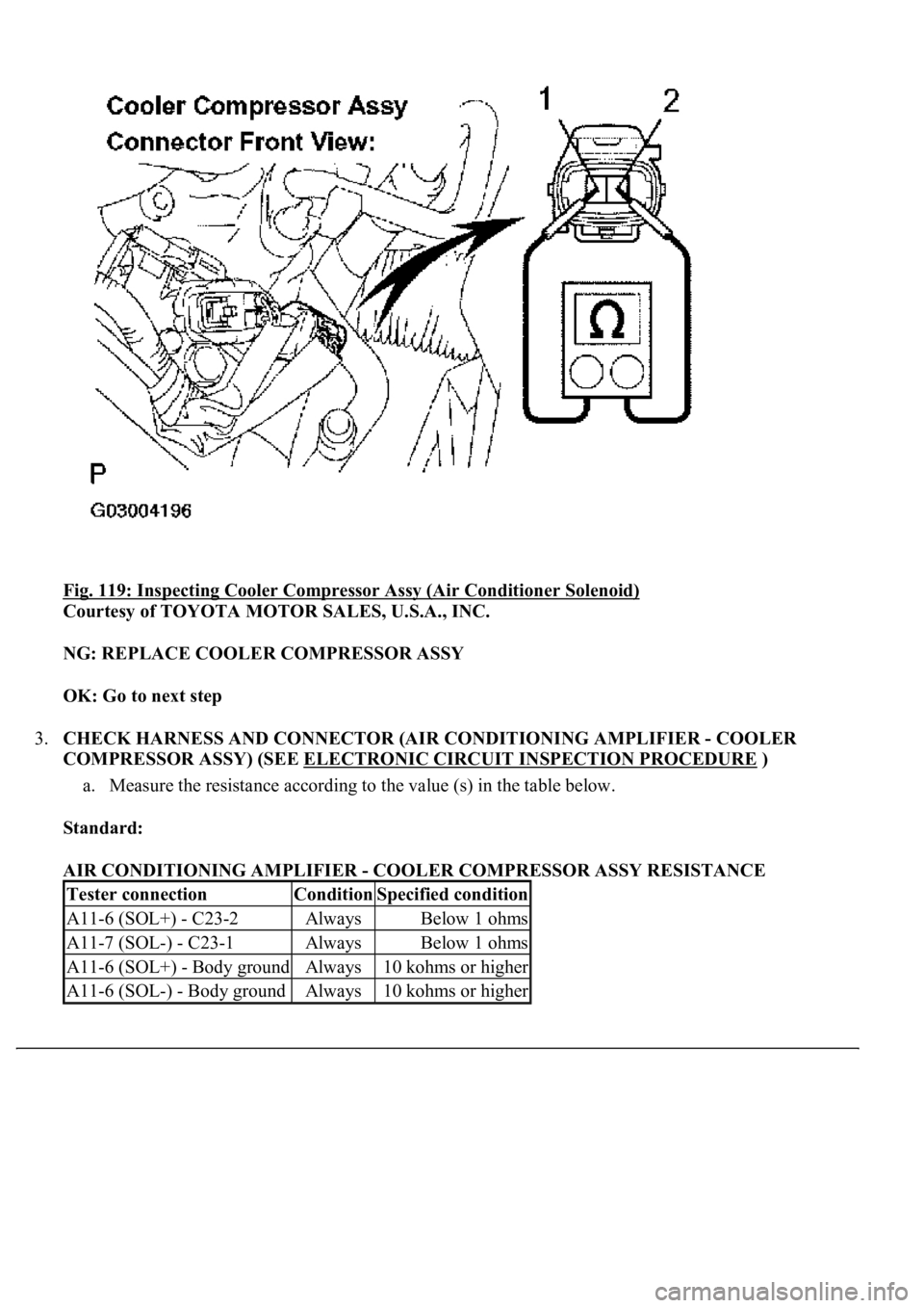
Fig. 119: Inspecting Cooler Compressor Assy (Air Conditioner Solenoid)
Courtesy of TOYOTA MOTOR SALES, U.S.A., INC.
NG: REPLACE COOLER COMPRESSOR ASSY
OK: Go to next step
3.CHECK HARNESS AND CONNECTOR (AIR CONDITIONING AMPLIFIER - COOLER
COMPRESSOR ASSY) (SEE ELECTRONIC CIRCUIT INSPECTION PROCEDURE
)
a. Measure the resistance according to the value (s) in the table below.
Standard:
AIR CONDITIONING AMPLIFIER - COOLER COMPRESSOR ASSY RESISTANCE
Tester connectionConditionSpecified condition
A11-6 (SOL+) - C23-2AlwaysBelow 1 ohms
A11-7 (SOL-) - C23-1AlwaysBelow 1 ohms
A11-6 (SOL+) - Body groundAlways10 kohms or higher
A11-6 (SOL-) - Body groundAlways10 kohms or higher
Page 355 of 4500
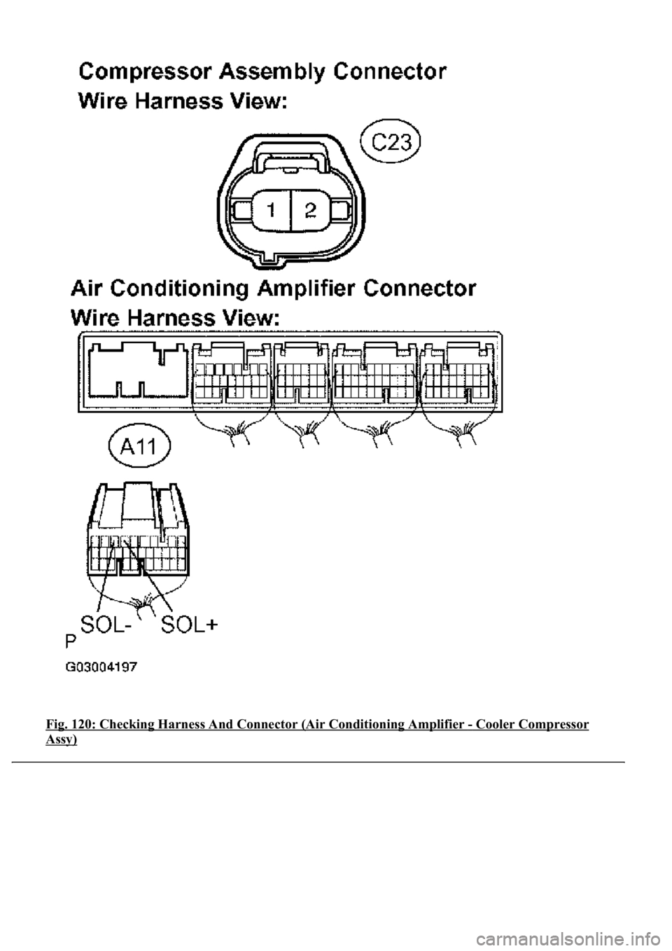
Fig. 120: Checking Harness And Connector (Air Conditioning Amplifier - Cooler Compressor
Assy)
Page 4244 of 4500
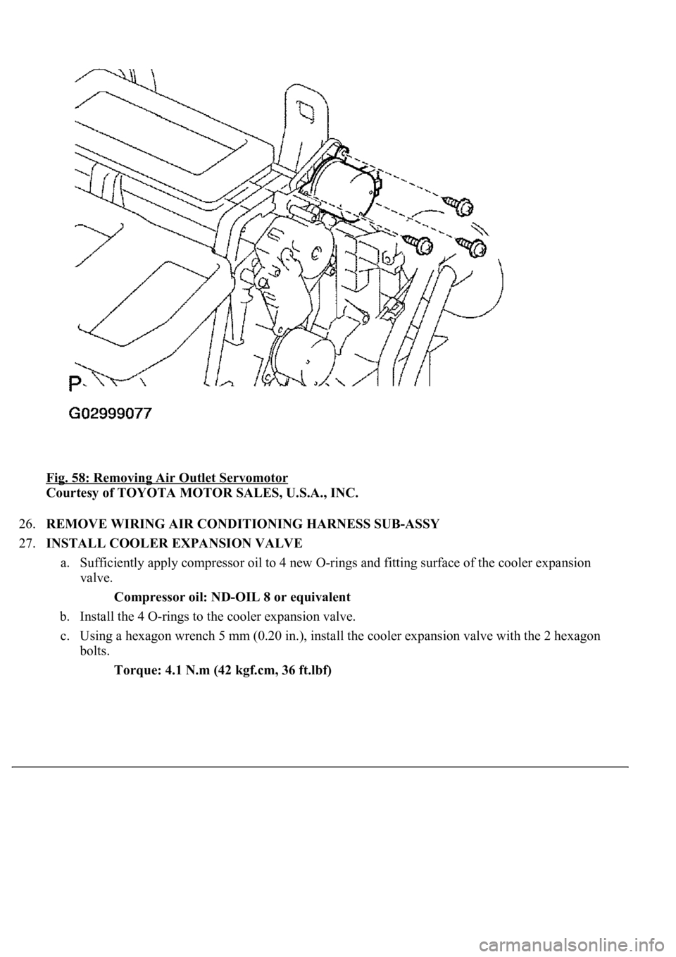
Fig. 58: Removing Air Outlet Servomotor
Courtesy of TOYOTA MOTOR SALES, U.S.A., INC.
26.REMOVE WIRING AIR CONDITIONING HARNESS SUB-ASSY
27.INSTALL COOLER EXPANSION VALVE
a. Sufficiently apply compressor oil to 4 new O-rings and fitting surface of the cooler expansion
valve.
Compressor oil: ND-OIL 8 or equivalent
b. Install the 4 O-rings to the cooler expansion valve.
c. Using a hexagon wrench 5 mm (0.20 in.), install the cooler expansion valve with the 2 hexagon
bolts.
Torque: 4.1 N.m (42 kgf.cm, 36 ft.lbf)
Page 4318 of 4500
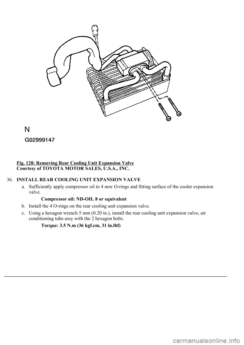
Fig. 128: Removing Rear Cooling Unit Expansion Valve
Courtesy of TOYOTA MOTOR SALES, U.S.A., INC.
36.INSTALL REAR COOLING UNIT EXPANSION VALVE
a. Sufficiently apply compressor oil to 4 new O-rings and fitting surface of the cooler expansion
valve.
Compressor oil: ND-OIL 8 or equivalent
b. Install the 4 O-rings on the rear cooling unit expansion valve.
c. Using a hexagon wrench 5 mm (0.20 in.), install the rear cooling unit expansion valve, air
conditioning tube assy with the 2 hexagon bolts.
Torque: 3.5 N.m (36 kgf.cm, 31 in.lbf)