check transmission fluid LEXUS LS430 2003 Factory Repair Manual
[x] Cancel search | Manufacturer: LEXUS, Model Year: 2003, Model line: LS430, Model: LEXUS LS430 2003Pages: 4500, PDF Size: 87.45 MB
Page 818 of 4500
PRECAUTION
1. The automatic transmission is composed of highly precision-finished parts which need careful inspection
before reassembly because even a small nick could cause fluid leakage or affect performance. The
instructions here are organized so that you work on only one component group at a time. This will help
avoid confusion from similar-looking parts of different sub-assemblies being on your workbench at the
same time. The component groups should be inspected and repaired from the converter housing side.
Inspect, repair and reassemble as much as possible before proceeding to the next component group. If a
defect is found in a certain component group during reassembly, inspect and repair this group
immediately. If a component group cannot be assembled because parts are being ordered, be sure to keep
all parts of the group in a separate container while proceeding with disassembly, inspection, repair and
reassembly of other component groups. Recommended ATF: ATF WS
2. All disassembled parts should be washed clean and any fluid passages and holes should be blown through
with compressed air.
3. Dry all parts with compressed air. Never use shop rags.
4. When using compressed air, be careful not to not aim at yourself to prevent accidentally spraying ATF or
kerosene on your face.
5. Only recommended automatic transaxle fluid or kerosene should be used for cleaning.
6. After cleaning, the parts should be arranged in the correct order for efficient inspection, repairs, and
reassembly.
7. When disassembling a valve body, be sure to match each valve together with the corresponding spring.
8. New discs for the brakes and clutches that are to be used for replacement must be soaked in ATF for at
least 15 minutes before reassembly.
9. All oil seal rings, clutch discs, clutch plates, rotating parts, and sliding surfaces should be coated with
ATF prior to reassembly.
10. All gaskets and rubber O-rings should be replaced.
11. Do not apply adhesive cements to gaskets or similar parts.
12. Make sure that the ends of a snap ring are not aligned with one of the cutouts and are installed in the
groove correctly.
13. When replacing a worn bushing, the sub-assembly containing the bushing must also be replaced.
14. Check thrust bearings and races for wear or damage. Replace them as necessary.
15. Use petroleum jelly to keep parts in place.
16. When working with FIPG material, perform the following: Using a razor blade and a gasket scraper,
remove all the old packing (FIPG) material from the gasket surface.
Thoroughly clean all components to remove any loose material.
Page 822 of 4500
HINT:
If you cannot add the listed amount of fluid, do the following:
1. Install the refill plug.
2. Allow the engine to idle with air conditioning OFF.
3. Move the shift lever through entire gear range to circulate fluid.
4. Wait for 30 seconds with the engine idling.
5. Stop the engine.
6. Remove the refill plug and add fluid.
7. Reinstall the refill plug.
4.FLUID CIRCULATION
a. Allow the engine to idle with the air conditioning OFF.
b. Move the shift lever through entire gear range to circulate fluid.
5.FLUID TEMPERATURE CHECK
a. With hand-held tester
1. Connect the han
d-held tester to the DLC3.
Output shaft oil seal replacement0.4 liters (0.42 US qts, 0.35 Imp. qts)
Transmission pan and drain plug removal1.3 liters (1.37 US qts, 1.14 Imp. qts)
Transmission valve body removal3.9 liters (4.12 US qts, 3.43 Imp. qts)
Torque converter replacement5.3 liters (5.60 US qts, 4.66 Imp. qts)
Entire transmission assembly7.2 liters (7.61 US qts, 6.34 Imp. qts)
Page 921 of 4500
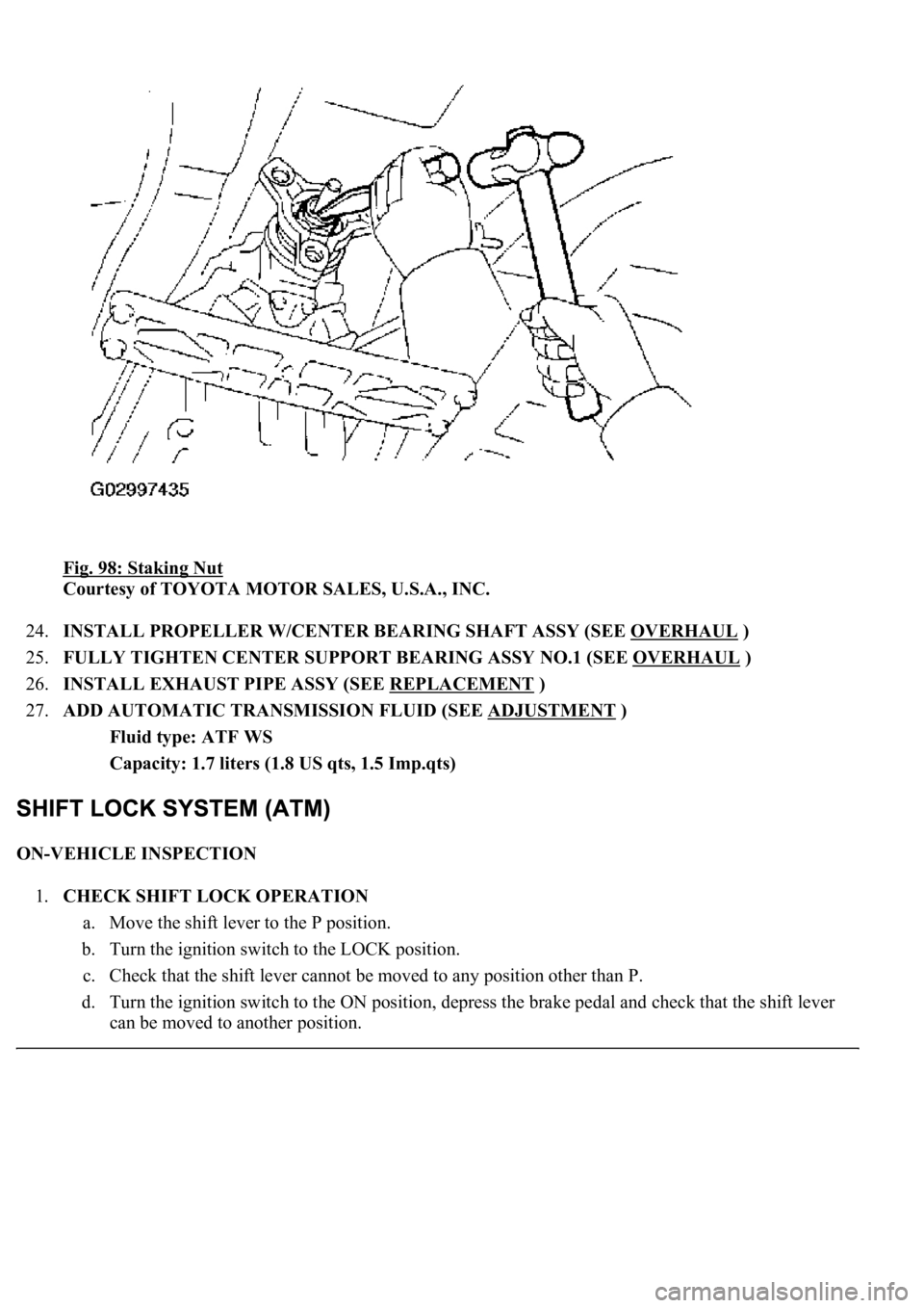
Fig. 98: Staking Nut
Courtesy of TOYOTA MOTOR SALES, U.S.A., INC.
24.INSTALL PROPELLER W/CENTER BEARING SHAFT ASSY (SEE OVERHAUL
)
25.FULLY TIGHTEN CENTER SUPPORT BEARING ASSY NO.1 (SEE OVERHAUL
)
26.INSTALL EXHAUST PIPE ASSY (SEE REPLACEMENT
)
27.ADD AUTOMATIC TRANSMISSION FLUID (SEE ADJUSTMENT
)
Fluid type: ATF WS
Capacity: 1.7 liters (1.8 US qts, 1.5 Imp.qts)
ON-VEHICLE INSPECTION
1.CHECK SHIFT LOCK OPERATION
a. Move the shift lever to the P position.
b. Turn the ignition switch to the LOCK position.
c. Check that the shift lever cannot be moved to any position other than P.
d. Turn the ignition switch to the ON position, depress the brake pedal and check that the shift lever
can be moved to another position.
Page 2676 of 4500
SYSTEM DESCRIPTION
1.SYSTEM DESCRIPTION
a. The ECT (Electronic controlled automatic transmission) is an automatic transmission that
electronically controls shift timing using the ECM. The ECM detects electrical signals that indicate
engine and driving conditions, and controls the shift point, based on driver habits and road
conditions. As a result, fuel efficiency and power transmission performance are improved.
<0036004b004c0049005700030056004b00520046004e0003004b00440056000300450048004800510003005500480047005800460048004700030045005c0003004600520051005700550052004f004f004c0051004a00030057004b004800030048005100
4a004c00510048000300440051004700030057005500440051[smission simultaneously. In
addition, the ECT has features such as follows:
Diagnostic function.
Fail-safe function when a malfunction occurs.
HOW TO PROCEED WITH TROUBLESHOOTING
HINT:
The ECM of this system is connected to the CAN and multiplex communication system. Therefore,
before starting troubleshooting, make sure to check that there is no trouble in the CAN and multiplex
communication system.
<0037004b00480003004b0044005100470010004b0048004f0047000300570048005600570048005500030046004400510003004500480003005800560048004700030044005700030056005700480053005600030016000f00030017000f00030019000f00
030044005100470003001c00110003[
1.Vehicle Brought to Workshop
2.Customer Problem Analysis (See CUSTOMER PROBLEM ANALYSIS CHECK
)
3.Connect the OBD II scan tool or hand-held tester to DLC3
4.Check and Clear DTCs and Freeze Frame Data (See DTC CHECK/CLEAR
)
5.Visual Inspection
6.Setting the Check Mode Diagnosis (See CHECK MODE PROCEDURE
)
7.Problem Symptom Confirmation (See ROAD TEST
)
Symptom does not occur: Go to step 8
Symptom occurs: Go to step 9
8.Symptom Simulation (See HOW TO PROCEED WITH TROUBLESHOOTING
)
9.DTC Check (See DTC CHECK/CLEAR
)
DTC is not output: Go to step 10
DTC is output: Go to step 17
10.Basic Inspection (See ADJUSTMENT
- AUTOMATIC TRANSMISSION FLUID ,
ADJUSTMENT
- PARK/NEUTRAL POSITION SWITCH ASSY and ADJUSTMENT -
FLOOR SHIFT ASSY
)
Page 2683 of 4500
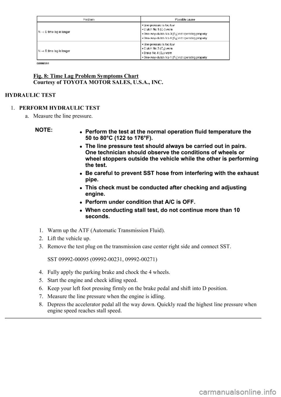
Fig. 8: Time Lag Problem Symptoms Chart
Courtesy of TOYOTA MOTOR SALES, U.S.A., INC.
HYDRAULIC TEST
1.PERFORM HYDRAULIC TEST
a. Measure the line pressure.
1. Warm up the ATF (Automatic Transmission Fluid).
2. Lift the vehicle up.
3. Remove the test plug on the transmission case center right side and connect SST.
SST 09992-00095 (09992-00231, 09992-00271)
4. Fully apply the parking brake and chock the 4 wheels.
5. Start the engine and check idling speed.
6. Keep your left foot pressing firmly on the brake pedal and shift into D position.
7. Measure the line pressure when the engine is idling.
8. Depress the accelerator pedal all the way down. Quickly read the highest line pressure when
en
gine speed reaches stall speed.
Page 2725 of 4500
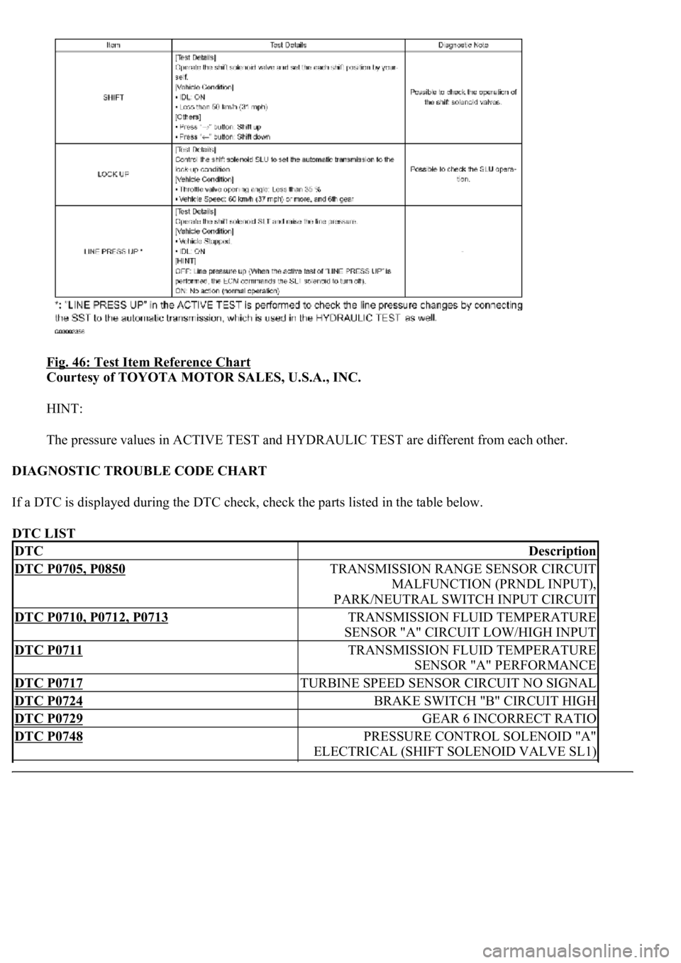
Fig. 46: Test Item Reference Chart
Courtesy of TOYOTA MOTOR SALES, U.S.A., INC.
HINT:
The pressure values in ACTIVE TEST and HYDRAULIC TEST are different from each other.
DIAGNOSTIC TROUBLE CODE CHART
If a DTC is displayed during the DTC check, check the parts listed in the table below.
DTC LIST
DTCDescription
DTC P0705, P0850TRANSMISSION RANGE SENSOR CIRCUIT
MALFUNCTION (PRNDL INPUT),
PARK/NEUTRAL SWITCH INPUT CIRCUIT
DTC P0710, P0712, P0713TRANSMISSION FLUID TEMPERATURE
SENSOR "A" CIRCUIT LOW/HIGH INPUT
DTC P0711TRANSMISSION FLUID TEMPERATURE
SENSOR "A" PERFORMANCE
DTC P0717TURBINE SPEED SENSOR CIRCUIT NO SIGNAL
DTC P0724BRAKE SWITCH "B" CIRCUIT HIGH
DTC P0729GEAR 6 INCORRECT RATIO
DTC P0748PRESSURE CONTROL SOLENOID "A"
ELECTRICAL (SHIFT SOLENOID VALVE SL1)
Page 2742 of 4500
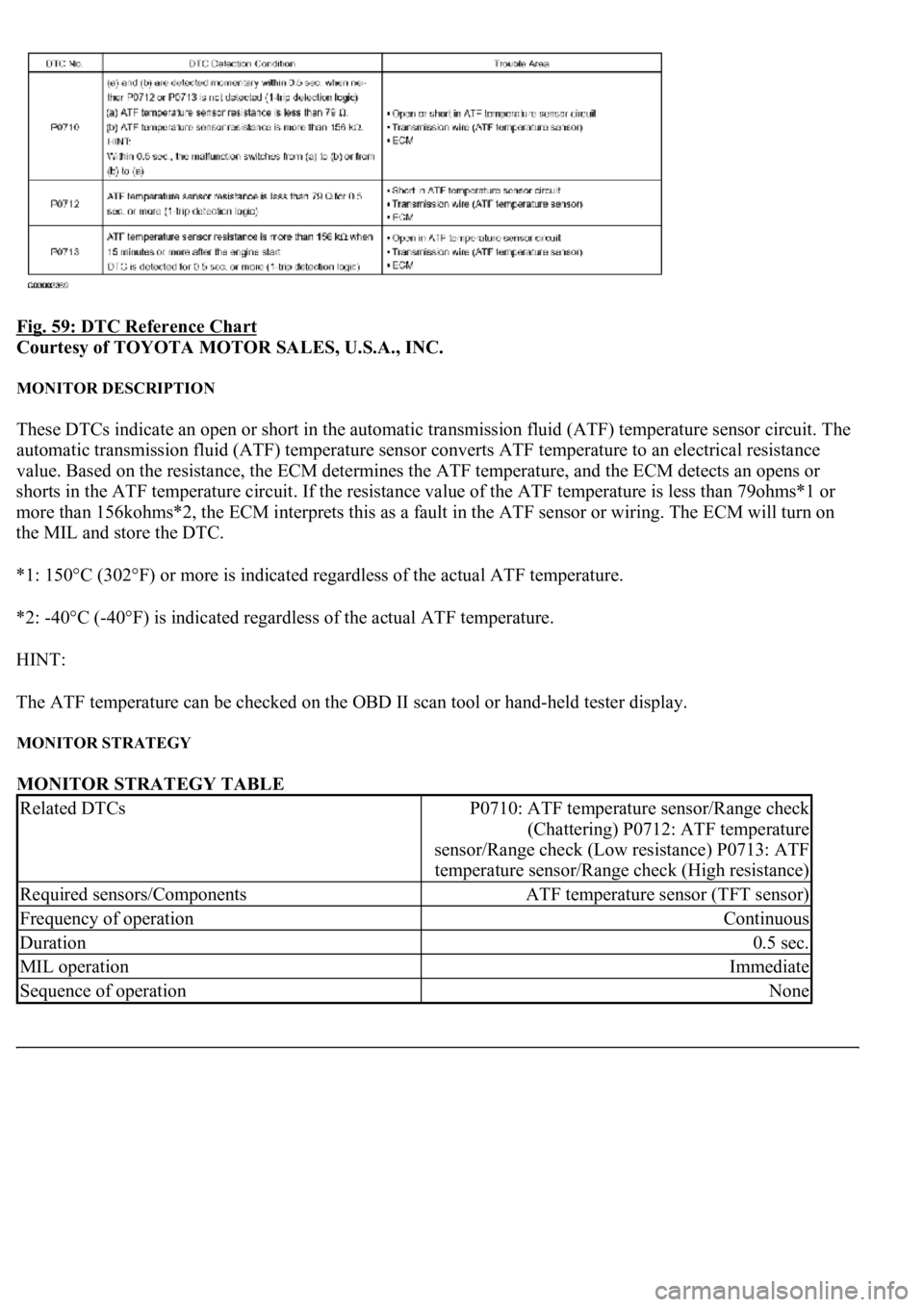
Fig. 59: DTC Reference Chart
Courtesy of TOYOTA MOTOR SALES, U.S.A., INC.
MONITOR DESCRIPTION
These DTCs indicate an open or short in the automatic transmission fluid (ATF) temperature sensor circuit. The
automatic transmission fluid (ATF) temperature sensor converts ATF temperature to an electrical resistance
value. Based on the resistance, the ECM determines the ATF temperature, and the ECM detects an opens or
shorts in the ATF temperature circuit. If the resistance value of the ATF temperature is less than 79ohms*1 or
more than 156kohms*2, the ECM interprets this as a fault in the ATF sensor or wiring. The ECM will turn on
the MIL and store the DTC.
*1: 150°C (302°F) or more is indicated regardless of the actual ATF temperature.
*2: -40°C (-40°F) is indicated regardless of the actual ATF temperature.
HINT:
The ATF temperature can be checked on the OBD II scan tool or hand-held tester display.
MONITOR STRATEGY
MONITOR STRATEGY TABLE
Related DTCsP0710: ATF temperature sensor/Range check
(Chattering) P0712: ATF temperature
sensor/Range check (Low resistance) P0713: ATF
temperature sensor/Range check (High resistance)
Required sensors/ComponentsATF temperature sensor (TFT sensor)
Frequency of operationContinuous
Duration0.5 sec.
MIL operationImmediate
Sequence of operationNone
Page 2743 of 4500
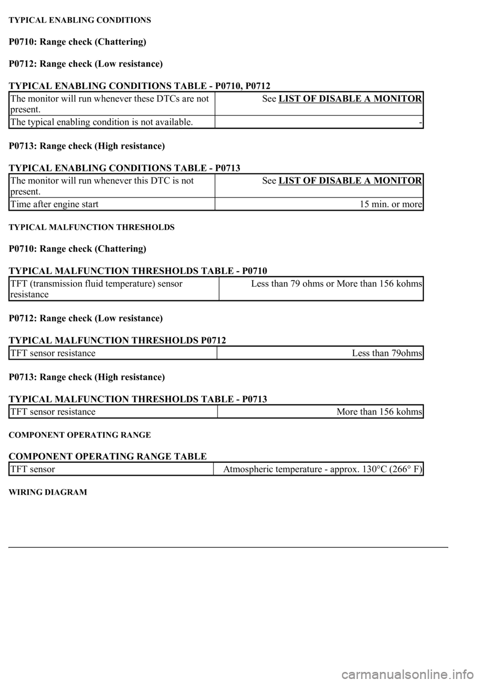
TYPICAL ENABLING CONDITIONS
P0710: Range check (Chattering)
P0712: Range check (Low resistance)
TYPICAL ENABLING CONDITIONS TABLE - P0710, P0712
P0713: Range check (High resistance)
TYPICAL ENABLING CONDITIONS TABLE - P0713
TYPICAL MALFUNCTION THRESHOLDS
P0710: Range check (Chattering)
TYPICAL MALFUNCTION THRESHOLDS TABLE - P0710
P0712: Range check (Low resistance)
TYPICAL MALFUNCTION THRESHOLDS P0712
P0713: Range check (High resistance)
TYPICAL MALFUNCTION THRESHOLDS TABLE - P0713
COMPONENT OPERATING RANGE
COMPONENT OPERATING RANGE TABLE
WIRING DIAGRAM
The monitor will run whenever these DTCs are not
present.See LIST OF DISABLE A MONITOR
The typical enabling condition is not available.-
The monitor will run whenever this DTC is not
present.See LIST OF DISABLE A MONITOR
Time after engine start15 min. or more
TFT (transmission fluid temperature) sensor
resistanceLess than 79 ohms or More than 156 kohms
TFT sensor resistanceLess than 79ohms
TFT sensor resistanceMore than 156 kohms
TFT sensorAtmospheric temperature - approx. 130°C (266° F)
Page 2748 of 4500
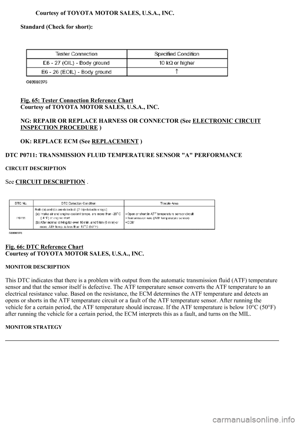
Courtesy of TOYOTA MOTOR SALES, U.S.A., INC.
Standard (Check for short):
Fig. 65: Tester Connection Reference Chart
Courtesy of TOYOTA MOTOR SALES, U.S.A., INC.
NG: REPAIR OR REPLACE HARNESS OR CONNECTOR (See ELECTRONIC CIRCUIT
INSPECTION PROCEDURE )
OK: REPLACE ECM (See REPLACEMENT
)
DTC P0711: TRANSMISSION FLUID TEMPERATURE SENSOR "A" PERFORMANCE
CIRCUIT DESCRIPTION
See CIRCUIT DESCRIPTION .
Fig. 66: DTC Reference Chart
Courtesy of TOYOTA MOTOR SALES, U.S.A., INC.
MONITOR DESCRIPTION
This DTC indicates that there is a problem with output from the automatic transmission fluid (ATF) temperature
sensor and that the sensor itself is defective. The ATF temperature sensor converts the ATF temperature to an
electrical resistance value. Based on the resistance, the ECM determines the ATF temperature and detects an
opens or shorts in the ATF temperature circuit or a fault of the ATF temperature sensor. After running the
vehicle for a certain period, the ATF temperature should increase. If the ATF temperature is below 10°C (50°F)
after running the vehicle for a certain period, the ECM interprets this as a fault, and turns on the MIL.
MONITOR STRATEGY
Page 2749 of 4500
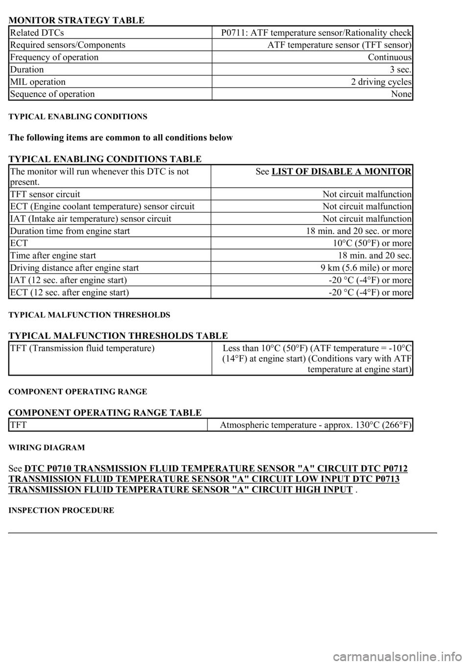
MONITOR STRATEGY TABLE
TYPICAL ENABLING CONDITIONS
The following items are common to all conditions below
TYPICAL ENABLING CONDITIONS TABLE
TYPICAL MALFUNCTION THRESHOLDS
TYPICAL MALFUNCTION THRESHOLDS TABLE
COMPONENT OPERATING RANGE
COMPONENT OPERATING RANGE TABLE
WIRING DIAGRAM
See DTC P0710 TRANSMISSION FLUID TEMPERATURE SENSOR "A" CIRCUIT DTC P0712
TRANSMISSION FLUID TEMPERATURE SENSOR "A" CIRCUIT LOW INPUT DTC P0713
TRANSMISSION FLUID TEMPERATURE SENSOR "A" CIRCUIT HIGH INPUT .
INSPECTION PROCEDURE
Related DTCsP0711: ATF temperature sensor/Rationality check
Required sensors/ComponentsATF temperature sensor (TFT sensor)
Frequency of operationContinuous
Duration3 sec.
MIL operation2 driving cycles
Sequence of operationNone
The monitor will run whenever this DTC is not
present.See LIST OF DISABLE A MONITOR
TFT sensor circuitNot circuit malfunction
ECT (Engine coolant temperature) sensor circuitNot circuit malfunction
IAT (Intake air temperature) sensor circuitNot circuit malfunction
Duration time from engine start18 min. and 20 sec. or more
ECT10°C (50°F) or more
Time after engine start18 min. and 20 sec.
Driving distance after engine start9 km (5.6 mile) or more
IAT (12 sec. after engine start)-20 °C (-4°F) or more
ECT (12 sec. after engine start)-20 °C (-4°F) or more
TFT (Transmission fluid temperature)Less than 10°C (50°F) (ATF temperature = -10°C
(14°F) at engine start) (Conditions vary with ATF
temperature at engine start)
TFTAtmospheric temperature - approx. 130°C (266°F)