cylinder head LEXUS LS430 2003 Factory Repair Manual
[x] Cancel search | Manufacturer: LEXUS, Model Year: 2003, Model line: LS430, Model: LEXUS LS430 2003Pages: 4500, PDF Size: 87.45 MB
Page 1018 of 4500
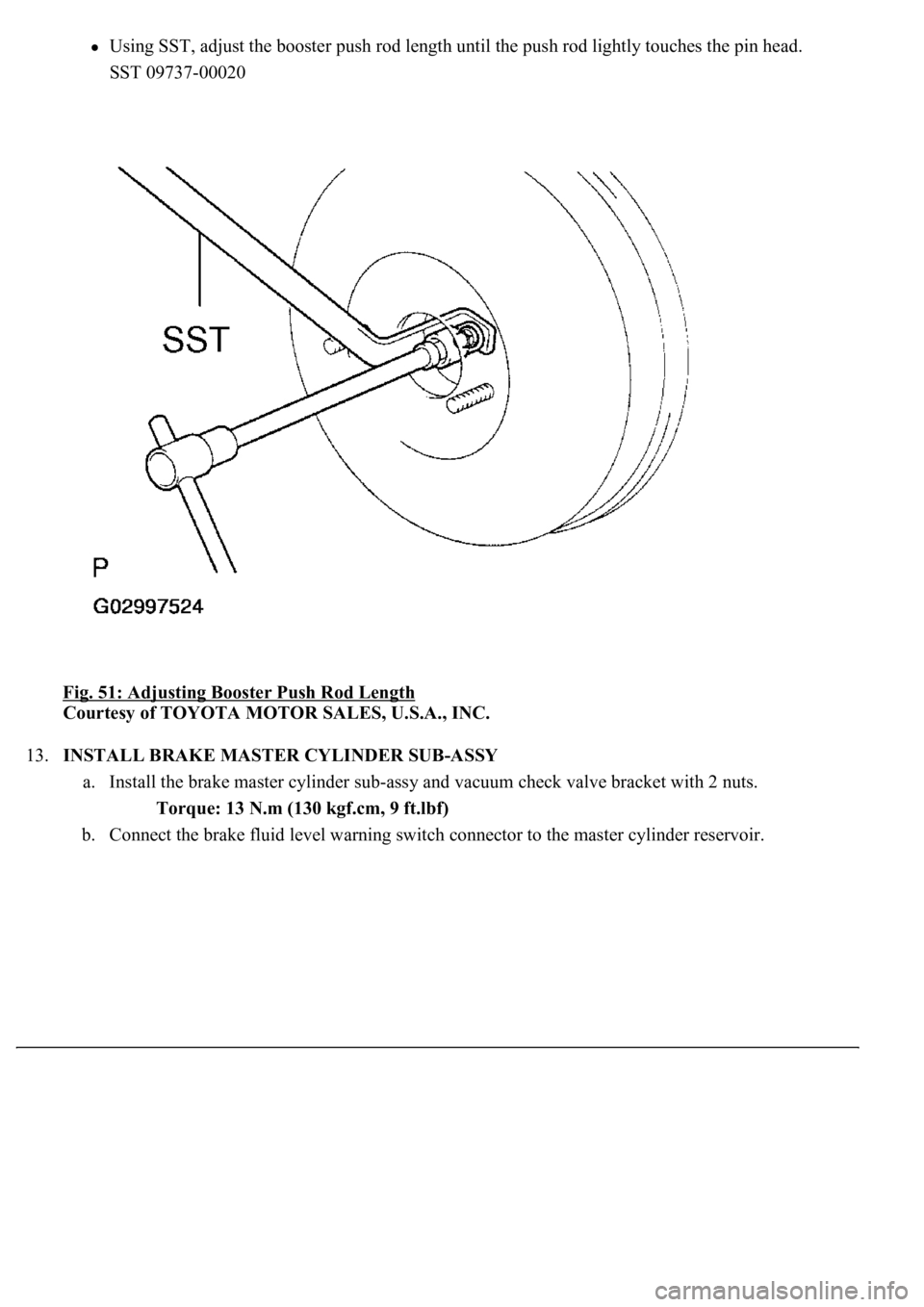
Using SST, adjust the booster push rod length until the push rod lightly touches the pin head.
SST 09737-00020
Fig. 51: Adjusting Booster Push Rod Length
Courtesy of TOYOTA MOTOR SALES, U.S.A., INC.
13.INSTALL BRAKE MASTER CYLINDER SUB-ASSY
a. Install the brake master cylinder sub-assy and vacuum check valve bracket with 2 nuts.
Torque: 13 N.m (130 kgf.cm, 9 ft.lbf)
b. Connect the brake fluid level warning switch connector to the master cylinder reservoir.
Page 1850 of 4500
psi), and check that the pressure does not drop.
If the pressure drops, check the hoses, radiator and water pump for leaks. If no external leaks are found,
check the heater core, cylinder block and head.
2.CHECK ENGINE COOLANT LEVEL AT RESERVOIR
a. Check that the engine coolant level is between the LOW and FULL lines when the engine is cold.
If the engine coolant is low, check for leaks and add "TOYOTA Super Long Life Coolant" to the
FULL line.
If "TOYOTA Super Long Life Coolant" is not available, use a similar high quality ethylene glycol
based non-silicate, non-amino, non-nitrite and non-borate coolant with long-life hybrid organic acid
technology. Do not substitute plain water for engine coolant.
3.CHECK ENGINE COOLANT QUALITY
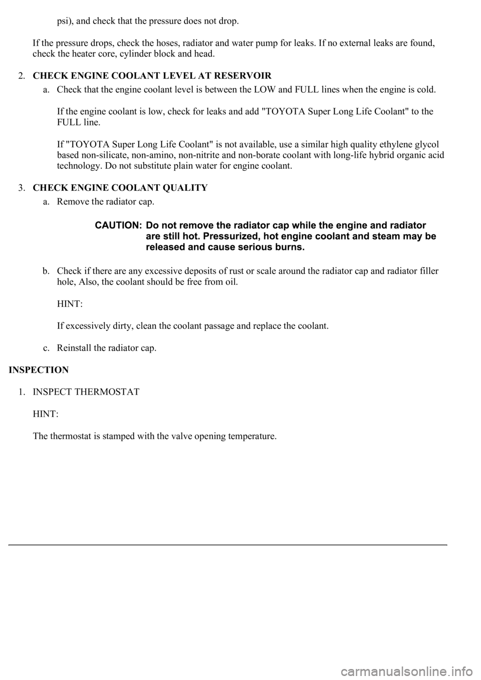
a. Remove the radiator cap.
b. Check if there are any excessive deposits of rust or scale around the radiator cap and radiator filler
hole, Also, the coolant should be free from oil.
HINT:
If excessively dirty, clean the coolant passage and replace the coolant.
c. Reinstall the radiator cap.
INSPECTION
1. INSPECT THERMOSTAT
HINT:
The thermostat is stamped with the valve openin
g temperature.
Page 2632 of 4500
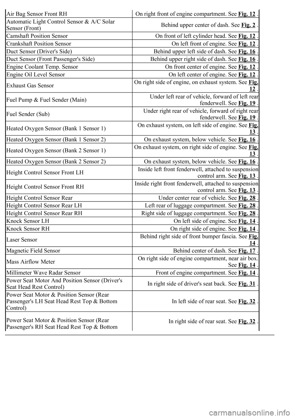
Air Bag Sensor Front RHOn right front of engine compartment. See Fig. 12 .
Automatic Light Control Sensor & A/C Solar
Sensor (Front)Behind upper center of dash. See Fig. 2 .
Camshaft Position SensorOn front of left cylinder head. See Fig. 12 .
Crankshaft Position SensorOn left front of engine. See Fig. 12 .
Duct Sensor (Driver's Side)Behind upper left side of dash. See Fig. 16 .
Duct Sensor (Front Passenger's Side)Behind upper right side of dash. See Fig. 16 .
Engine Coolant Temp. SensorOn front center of engine. See Fig. 12 .
Engine Oil Level SensorOn left center of engine. See Fig. 12 .
Exhaust Gas SensorOn right side of engine, on exhaust system. See Fig.
12 .
Fuel Pump & Fuel Sender (Main)Under left rear of vehicle, forward of left rear
fenderwell. See Fig. 19
.
Fuel Sender (Sub)Under right rear of vehicle, forward of right rear
fenderwell. See Fig. 19
.
Heated Oxygen Sensor (Bank 1 Sensor 1)On exhaust system, on left side of engine. See Fig.
13 .
Heated Oxygen Sensor (Bank 1 Sensor 2)On exhaust system, below vehicle. See Fig. 16 .
Heated Oxygen Sensor (Bank 2 Sensor 1)On exhaust system, on right side of engine. See Fig.
13 .
Heated Oxygen Sensor (Bank 2 Sensor 2)On exhaust system, below vehicle. See Fig. 16 .
Height Control Sensor Front LHInside left front fenderwell, attached to suspension
control arm. See Fig. 13
.
Height Control Sensor Front RHInside right front fenderwell, attached to suspension
control arm. See Fig. 13
.
Height Control Sensor RearUnder center rear of vehicle. See Fig. 28 .
Height Control Sensor Rear LHLeft rear of luggage compartment. See Fig. 28 .
Height Control Sensor Rear RHRight side of luggage compartment. See Fig. 28 .
Knock Sensor LHOn left side of engine. See Fig. 14 .
Knock Sensor RHOn right side of engine. See Fig. 14 .
Laser SensorBehind right side of front bumper fascia. See Fig.
14 .
Magnetic Field SensorBehind center of dash. See Fig. 17 .
Mass Airflow MeterOn right side of engine compartment, near air box.
See Fig. 14
.
Millimeter Wave Radar SensorFront of engine compartment. See Fig. 14 .
Power Seat Motor And Position Sensor (Driver's
Seat Head Rest Control)In right side of driver's seat back. See Fig. 31 .
Power Seat Motor & Position Sensor (Rear
Passenger's LH Seat Head Rest Top & Bottom
Control)
In left side of rear seat. See Fig. 32 .
Power Seat Motor & Position Sensor (Rear
Passenger's RH Seat Head Rest Top & Bottom In right side of rear seat. See Fig. 32 .
Page 2634 of 4500
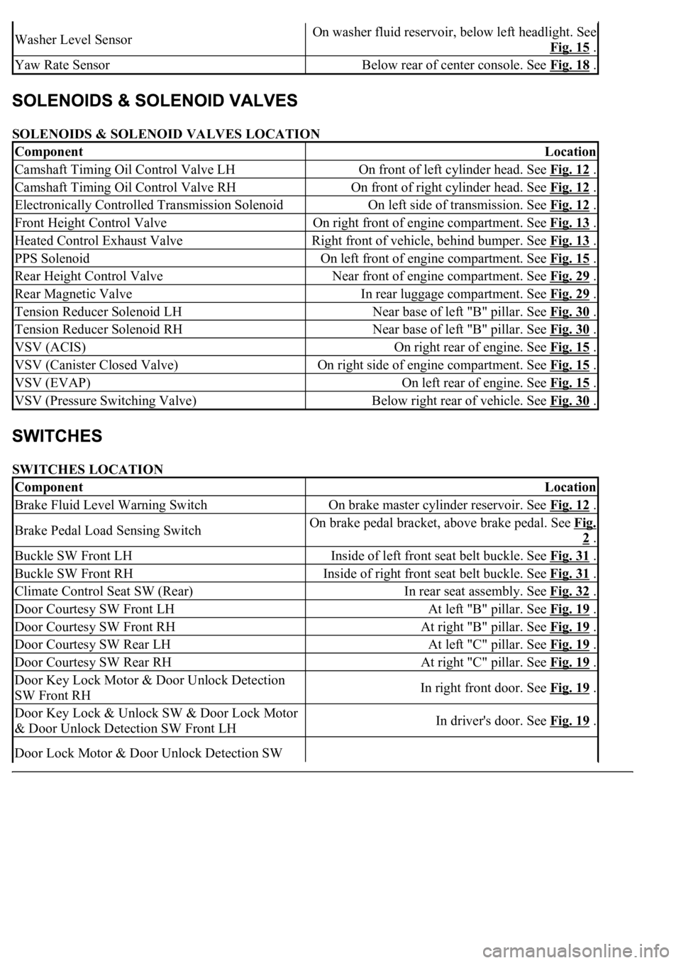
SOLENOIDS & SOLENOID VALVES LOCATION
SWITCHES LOCATION
Washer Level SensorOn washer fluid reservoir, below left headlight. See
Fig. 15
.
Yaw Rate SensorBelow rear of center console. See Fig. 18 .
ComponentLocation
Camshaft Timing Oil Control Valve LHOn front of left cylinder head. See Fig. 12 .
Camshaft Timing Oil Control Valve RHOn front of right cylinder head. See Fig. 12 .
Electronically Controlled Transmission SolenoidOn left side of transmission. See Fig. 12 .
Front Height Control ValveOn right front of engine compartment. See Fig. 13 .
Heated Control Exhaust ValveRight front of vehicle, behind bumper. See Fig. 13 .
PPS SolenoidOn left front of engine compartment. See Fig. 15 .
Rear Height Control ValveNear front of engine compartment. See Fig. 29 .
Rear Magnetic ValveIn rear luggage compartment. See Fig. 29 .
Tension Reducer Solenoid LHNear base of left "B" pillar. See Fig. 30 .
Tension Reducer Solenoid RHNear base of left "B" pillar. See Fig. 30 .
VSV (ACIS)On right rear of engine. See Fig. 15 .
VSV (Canister Closed Valve)On right side of engine compartment. See Fig. 15 .
VSV (EVAP)On left rear of engine. See Fig. 15 .
VSV (Pressure Switching Valve)Below right rear of vehicle. See Fig. 30 .
ComponentLocation
Brake Fluid Level Warning SwitchOn brake master cylinder reservoir. See Fig. 12 .
Brake Pedal Load Sensing SwitchOn brake pedal bracket, above brake pedal. See Fig.
2 .
Buckle SW Front LHInside of left front seat belt buckle. See Fig. 31 .
Buckle SW Front RHInside of right front seat belt buckle. See Fig. 31 .
Climate Control Seat SW (Rear)In rear seat assembly. See Fig. 32 .
Door Courtesy SW Front LHAt left "B" pillar. See Fig. 19 .
Door Courtesy SW Front RHAt right "B" pillar. See Fig. 19 .
Door Courtesy SW Rear LHAt left "C" pillar. See Fig. 19 .
Door Courtesy SW Rear RHAt right "C" pillar. See Fig. 19 .
Door Key Lock Motor & Door Unlock Detection
SW Front RHIn right front door. See Fig. 19 .
Door Key Lock & Unlock SW & Door Lock Motor
& Door Unlock Detection SW Front LHIn driver's door. See Fig. 19 .
Door Lock Motor & Door Unlock Detection SW
Page 2639 of 4500
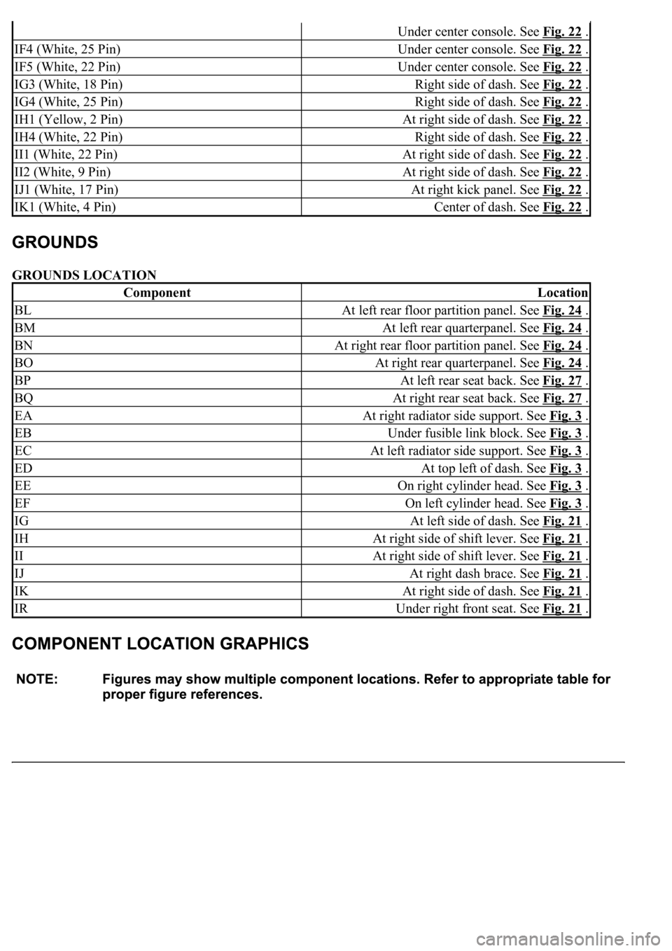
GROUNDS LOCATION
Under center console. See Fig. 22 .
IF4 (White, 25 Pin)Under center console. See Fig. 22 .
IF5 (White, 22 Pin)Under center console. See Fig. 22 .
IG3 (White, 18 Pin)Right side of dash. See Fig. 22 .
IG4 (White, 25 Pin)Right side of dash. See Fig. 22 .
IH1 (Yellow, 2 Pin)At right side of dash. See Fig. 22 .
IH4 (White, 22 Pin)Right side of dash. See Fig. 22 .
II1 (White, 22 Pin)At right side of dash. See Fig. 22 .
II2 (White, 9 Pin)At right side of dash. See Fig. 22 .
IJ1 (White, 17 Pin)At right kick panel. See Fig. 22 .
IK1 (White, 4 Pin)Center of dash. See Fig. 22 .
ComponentLocation
BLAt left rear floor partition panel. See Fig. 24 .
BMAt left rear quarterpanel. See Fig. 24 .
BNAt right rear floor partition panel. See Fig. 24 .
BOAt right rear quarterpanel. See Fig. 24 .
BPAt left rear seat back. See Fig. 27 .
BQAt right rear seat back. See Fig. 27 .
EAAt right radiator side support. See Fig. 3 .
EBUnder fusible link block. See Fig. 3 .
ECAt left radiator side support. See Fig. 3 .
EDAt top left of dash. See Fig. 3 .
EEOn right cylinder head. See Fig. 3 .
EFOn left cylinder head. See Fig. 3 .
IGAt left side of dash. See Fig. 21 .
IHAt right side of shift lever. See Fig. 21 .
IIAt right side of shift lever. See Fig. 21 .
IJAt right dash brace. See Fig. 21 .
IKAt right side of dash. See Fig. 21 .
IRUnder right front seat. See Fig. 21 .
Page 2913 of 4500
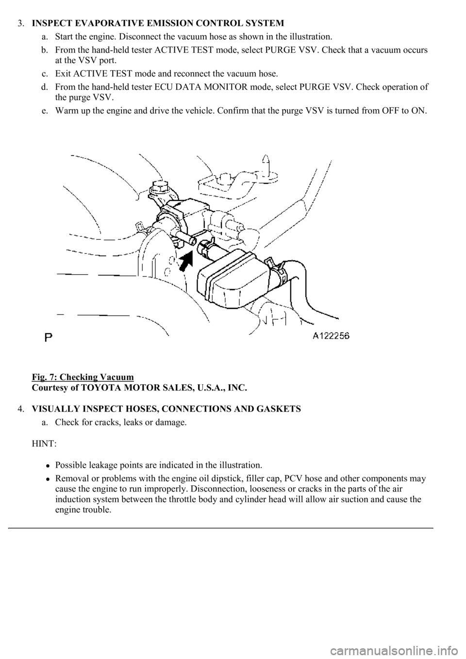
3.INSPECT EVAPORATIVE EMISSION CONTROL SYSTEM
a. Start the engine. Disconnect the vacuum hose as shown in the illustration.
b. From the hand-held tester ACTIVE TEST mode, select PURGE VSV. Check that a vacuum occurs
at the VSV port.
c. Exit ACTIVE TEST mode and reconnect the vacuum hose.
d. From the hand-held tester ECU DATA MONITOR mode, select PURGE VSV. Check operation of
the purge VSV.
e. Warm up the engine and drive the vehicle. Confirm that the purge VSV is turned from OFF to ON.
Fig. 7: Checking Vacuum
Courtesy of TOYOTA MOTOR SALES, U.S.A., INC.
4.VISUALLY INSPECT HOSES, CONNECTIONS AND GASKETS
a. Check for cracks, leaks or damage.
HINT:
Possible leakage points are indicated in the illustration.
Removal or problems with the engine oil dipstick, filler cap, PCV hose and other components may
cause the engine to run improperly. Disconnection, looseness or cracks in the parts of the air
induction system between the throttle body and cylinder head will allow air suction and cause the
engine trouble.
Page 2925 of 4500
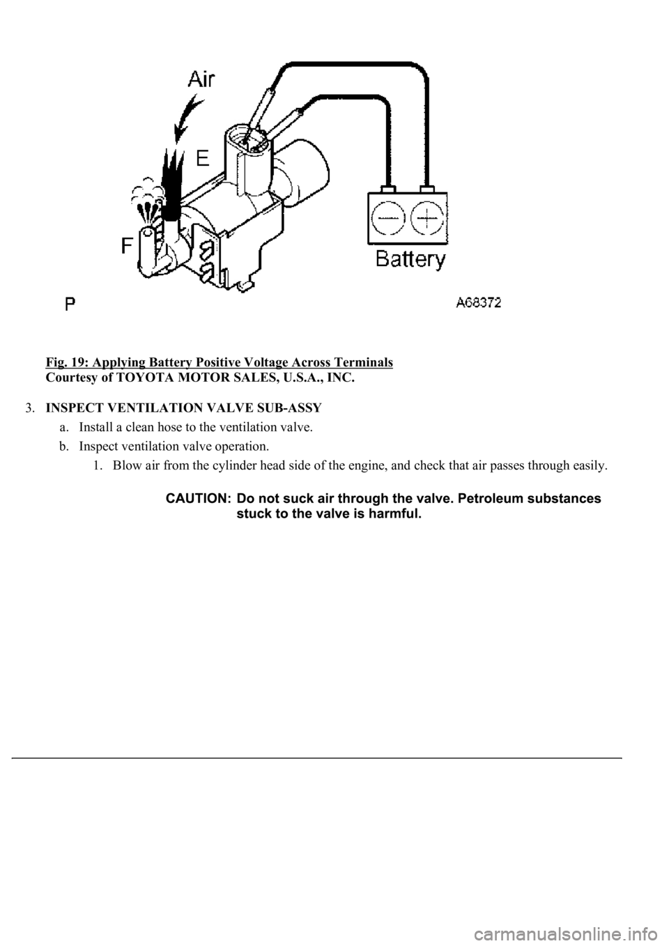
Fig. 19: Applying Battery Positive Voltage Across Terminals
Courtesy of TOYOTA MOTOR SALES, U.S.A., INC.
3.INSPECT VENTILATION VALVE SUB-ASSY
a. Install a clean hose to the ventilation valve.
b. Inspect ventilation valve operation.
1. Blow air from the cylinder head side of the engine, and check that air passes through easily.
Page 2964 of 4500
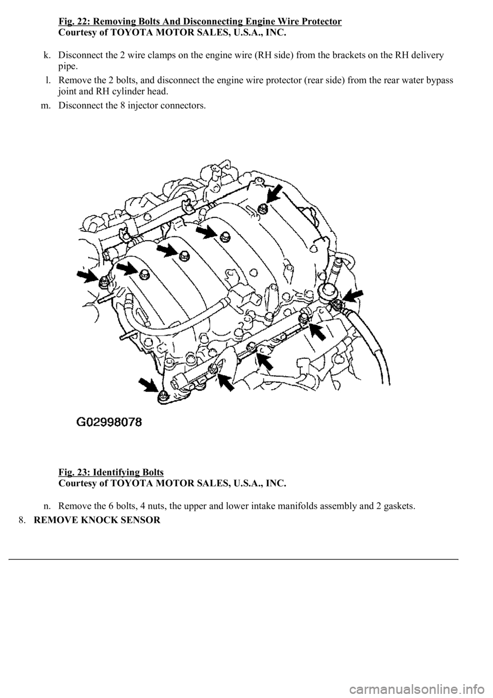
Fig. 22: Removing Bolts And Disconnecting Engine Wire Protector
Courtesy of TOYOTA MOTOR SALES, U.S.A., INC.
k. Disconnect the 2 wire clamps on the engine wire (RH side) from the brackets on the RH delivery
pipe.
l. Remove the 2 bolts, and disconnect the engine wire protector (rear side) from the rear water bypass
joint and RH cylinder head.
m. Disconnect the 8 injector connectors.
Fig. 23: Identifying Bolts
Courtesy of TOYOTA MOTOR SALES, U.S.A., INC.
n. Remove the 6 bolts, 4 nuts, the upper and lower intake manifolds assembly and 2 gaskets.
8.REMOVE KNOCK SENSOR
Page 2967 of 4500
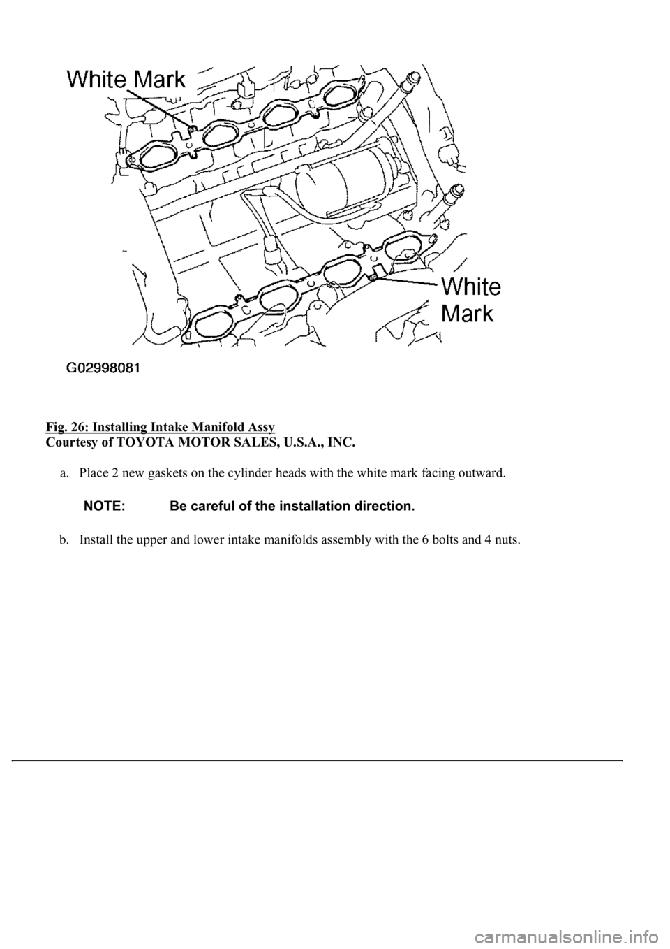
Fig. 26: Installing Intake Manifold Assy
Courtesy of TOYOTA MOTOR SALES, U.S.A., INC.
a. Place 2 new gaskets on the cylinder heads with the white mark facing outward.
b. Install the upper and lower intake manifolds assembly with the 6 bolts and 4 nuts.
Page 3290 of 4500
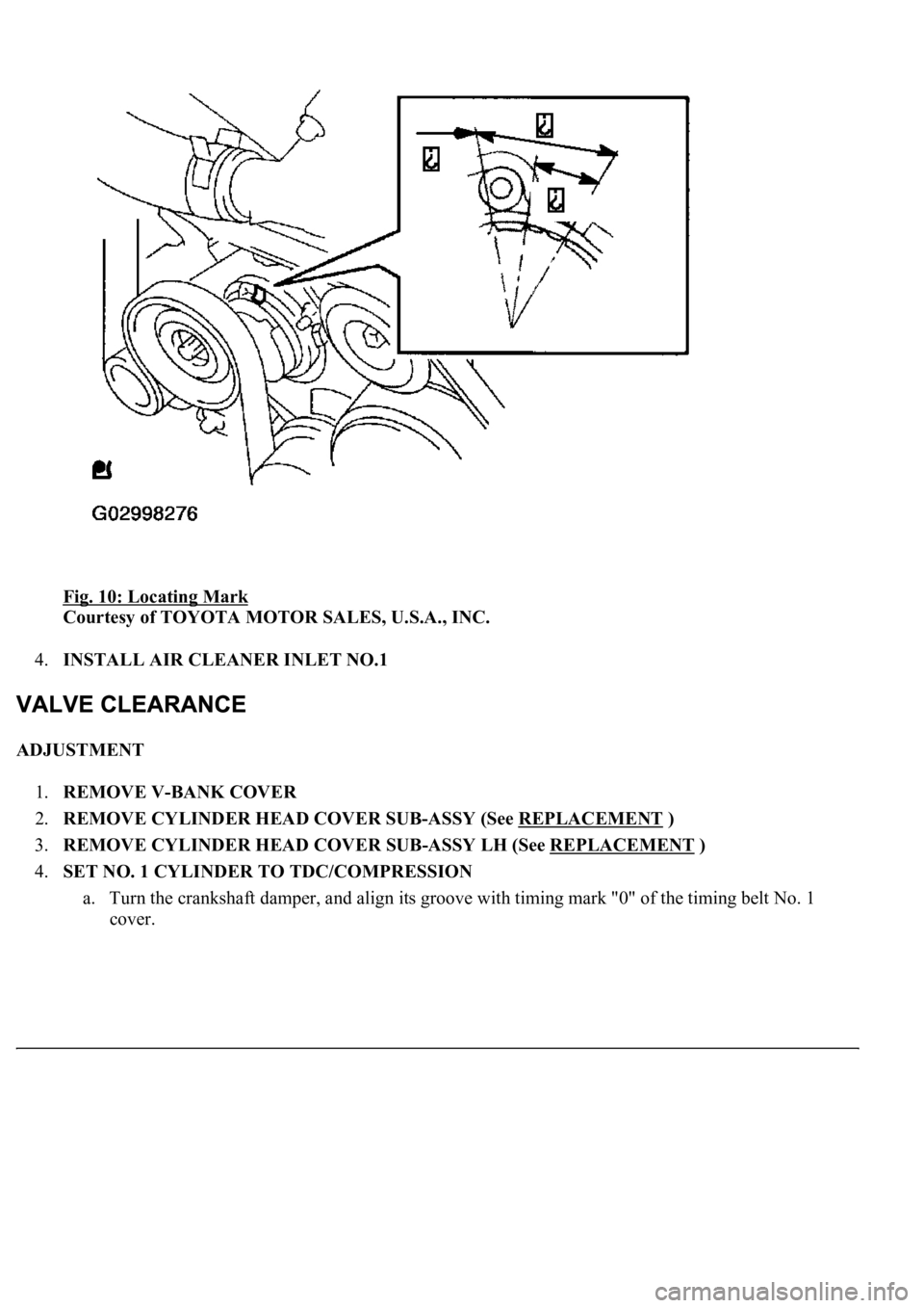
Fig. 10: Locating Mark
Courtesy of TOYOTA MOTOR SALES, U.S.A., INC.
4.INSTALL AIR CLEANER INLET NO.1
ADJUSTMENT
1.REMOVE V-BANK COVER
2.REMOVE CYLINDER HEAD COVER SUB-ASSY (See REPLACEMENT
)
3.REMOVE CYLINDER HEAD COVER SUB-ASSY LH (See REPLACEMENT
)
4.SET NO. 1 CYLINDER TO TDC/COMPRESSION
a. Turn the crankshaft damper, and align its groove with timing mark "0" of the timing belt No. 1
cover.