fuel system LEXUS LS430 2003 Factory Repair Manual
[x] Cancel search | Manufacturer: LEXUS, Model Year: 2003, Model line: LS430, Model: LEXUS LS430 2003Pages: 4500, PDF Size: 87.45 MB
Page 2 of 4500
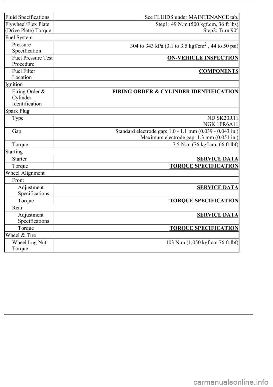
Fluid SpecificationsSee FLUIDS under MAINTENANCE tab.
Flywheel/Flex Plate
(Drive Plate) TorqueStep1: 49 N.m (500 kgf.cm, 36 ft lbs)
Step2: Turn 90°
Fuel System
Pressure
Specification304 to 343 kPa (3.1 to 3.5 kgf/cm2 , 44 to 50 psi)
Fuel Pressure Test
ProcedureON-VEHICLE INSPECTION
Fuel Filter
LocationCOMPONENTS
Ignition
Firing Order &
Cylinder
IdentificationFIRING ORDER & CYLINDER IDENTIFICATION
Spark Plug
TypeND SK20R11
NGK 1FR6A11
GapStandard electrode gap: 1.0 - 1.1 mm (0.039 - 0.043 in.)
Maximum electrode gap: 1.3 mm (0.051 in.)
Torque7.5 N.m (76 kgf.cm, 66 ft.lbf)
Starting
StarterSERVICE DATA
TorqueTORQUE SPECIFICATION
Wheel Alignment
Front
Adjustment
SpecificationsSERVICE DATA
TorqueTORQUE SPECIFICATION
Rear
Adjustment
SpecificationsSERVICE DATA
TorqueTORQUE SPECIFICATION
Wheel & Tire
Wheel Lug Nut
Torque103 N.m (1,050 kgf.cm 76 ft.lbf)
Page 749 of 4500
NG: REPLACE THE CD
OK: Go to next step
3.CHECK RADIO RECEIVER ASSY
a. Insert another CD and check if it is ejected.
OK: The disc is ejected.
NG: REPLACE RADIO RECEIVER ASSY (SEE REPLACEMENT
)
OK: NORMAL OPERATION
INSPECTION PROCEDURE
1.CHECK SPEAKERS
a. Check the speaker unit installed condition.
1. Check that each speaker is securely installed.
OK: The problem goes away.
HINT:
The radio has a noise prevention function to reduce noise when listening to the radio. If a loud noise
occurs, check whether the ground at the antenna mounting base and the noise prevention unit are installed
and wired correctly.
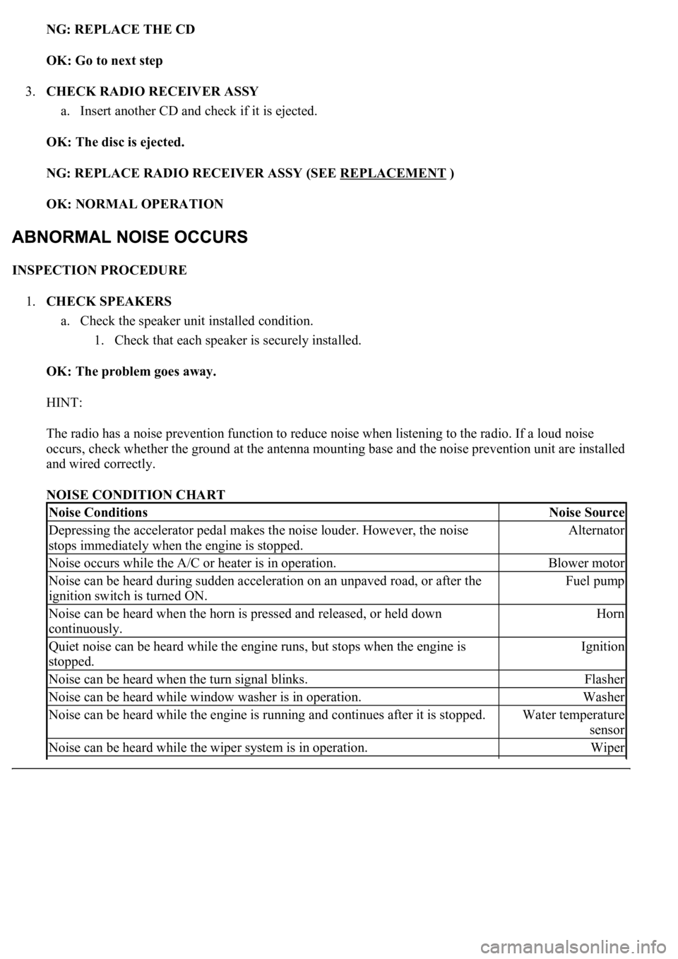
NOISE CONDITION CHART
Noise ConditionsNoise Source
Depressing the accelerator pedal makes the noise louder. However, the noise
stops immediately when the engine is stopped.Alternator
Noise occurs while the A/C or heater is in operation.Blower motor
Noise can be heard during sudden acceleration on an unpaved road, or after the
ignition switch is turned ON.Fuel pump
Noise can be heard when the horn is pressed and released, or held down
continuously.Horn
<00340058004c00480057000300510052004c0056004800030046004400510003004500480003004b00480044005500470003005a004b004c004f004800030057004b0048000300480051004a004c0051004800030055005800510056000f00030045005800
570003005600570052005300560003005a004b004800510003[the engine is
stopped.Ignition
Noise can be heard when the turn signal blinks.Flasher
Noise can be heard while window washer is in operation.Washer
Noise can be heard while the engine is running and continues after it is stopped.Water temperature
sensor
Noise can be heard while the wiper system is in operation.Wiper
Page 1756 of 4500
Once calibration is completed, it is not necessary to perform the above procedures unless the magnetic
field strength is drastically changed.
HINT:
Inspect the related "Fuse" and "Relay" before confirming the suspected area as shown in the charts below.
MALFUNCTION SYSTEM:
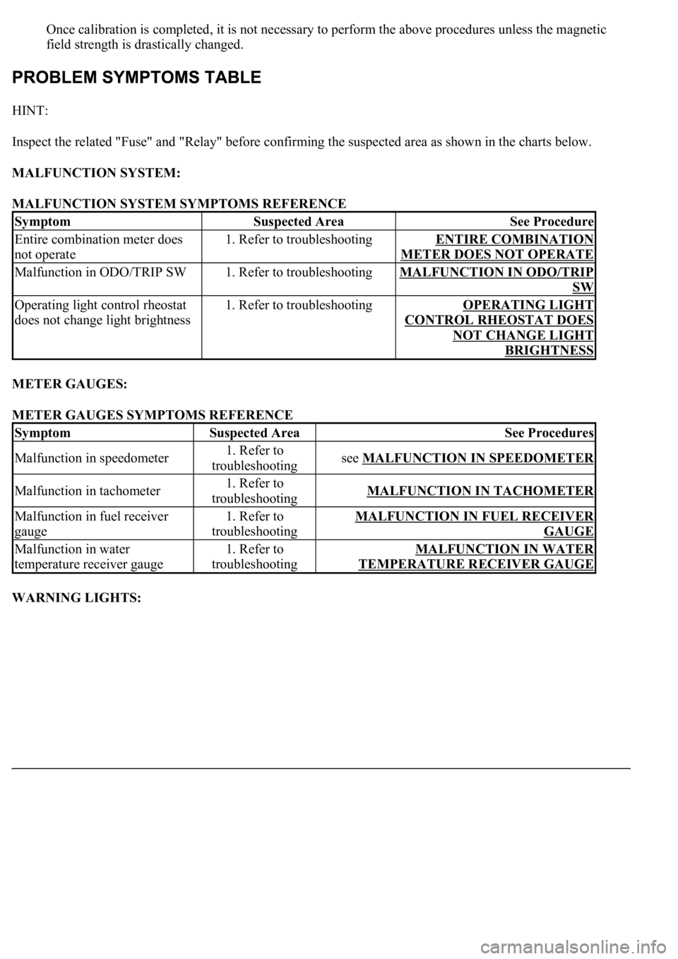
MALFUNCTION SYSTEM SYMPTOMS REFERENCE
METER GAUGES:
METER GAUGES SYMPTOMS REFERENCE
WARNING LIGHTS:
SymptomSuspected AreaSee Procedure
Entire combination meter does
not operate1. Refer to troubleshootingENTIRE COMBINATION
METER DOES NOT OPERATE
Malfunction in ODO/TRIP SW1. Refer to troubleshootingMALFUNCTION IN ODO/TRIP
SW
Operating light control rheostat
does not change light brightness1. Refer to troubleshootingOPERATING LIGHT
CONTROL RHEOSTAT DOES
NOT CHANGE LIGHT
BRIGHTNESS
SymptomSuspected AreaSee Procedures
Malfunction in speedometer1. Refer to
troubleshootingsee MALFUNCTION IN SPEEDOMETER
Malfunction in tachometer1. Refer to
troubleshootingMALFUNCTION IN TACHOMETER
Malfunction in fuel receiver
gauge1. Refer to
troubleshootingMALFUNCTION IN FUEL RECEIVER
GAUGE
Malfunction in water
temperature receiver gauge1. Refer to
troubleshootingMALFUNCTION IN WATER
TEMPERATURE RECEIVER GAUGE
Page 1798 of 4500
Courtesy of TOYOTA MOTOR SALES, U.S.A., INC.
OK: GO TO ENGINE CONTROL SYSTEM (SEE REPLACEMENT
)
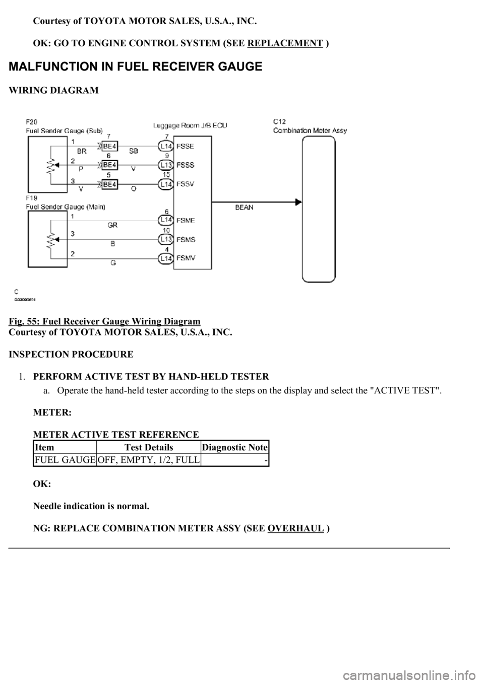
WIRING DIAGRAM
Fig. 55: Fuel Receiver Gauge Wiring Diagram
Courtesy of TOYOTA MOTOR SALES, U.S.A., INC.
INSPECTION PROCEDURE
1.PERFORM ACTIVE TEST BY HAND-HELD TESTER
a. Operate the hand-held tester according to the steps on the display and select the "ACTIVE TEST".
METER:
METER ACTIVE TEST REFERENCE
OK:
Needle indication is normal.
NG: REPLACE COMBINATION METER ASSY (SEE OVERHAUL
)
ItemTest DetailsDiagnostic Note
FUEL GAUGEOFF, EMPTY, 1/2, FULL-
Page 1810 of 4500
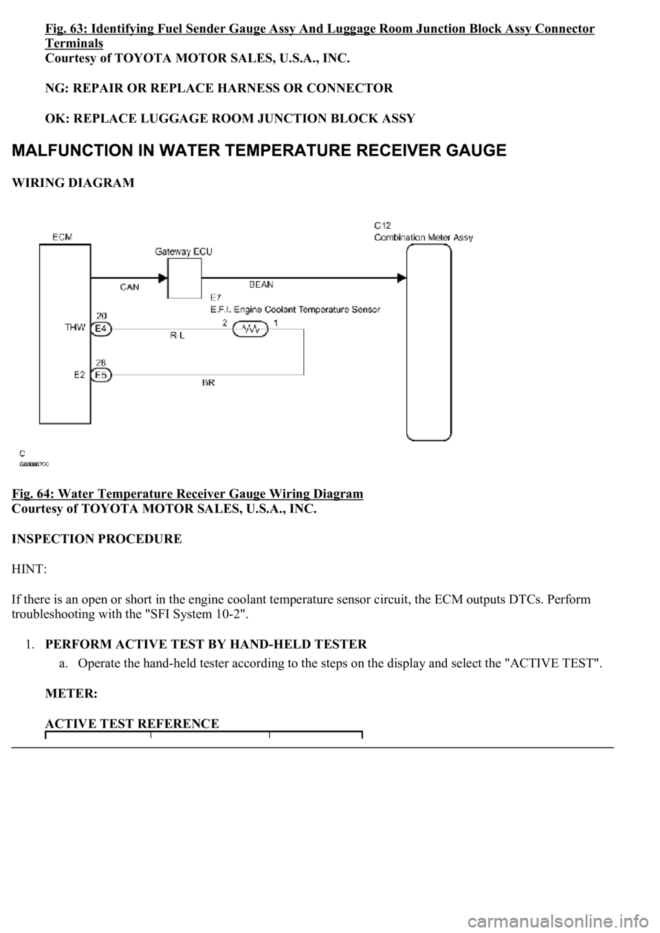
Fig. 63: Identifying Fuel Sender Gauge Assy And Luggage Room Junction Block Assy Connector
Terminals
Courtesy of TOYOTA MOTOR SALES, U.S.A., INC.
NG: REPAIR OR REPLACE HARNESS OR CONNECTOR
OK: REPLACE LUGGAGE ROOM JUNCTION BLOCK ASSY
WIRING DIAGRAM
Fig. 64: Water Temperature Receiver Gauge Wiring Diagram
Courtesy of TOYOTA MOTOR SALES, U.S.A., INC.
INSPECTION PROCEDURE
HINT:
If there is an open or short in the engine coolant temperature sensor circuit, the ECM outputs DTCs. Perform
troubleshooting with the "SFI System 10-2".
1.PERFORM ACTIVE TEST BY HAND-HELD TESTER
a. Operate the hand-held tester according to the steps on the display and select the "ACTIVE TEST".
METER:
ACTIVE TEST REFERENCE
Page 2036 of 4500
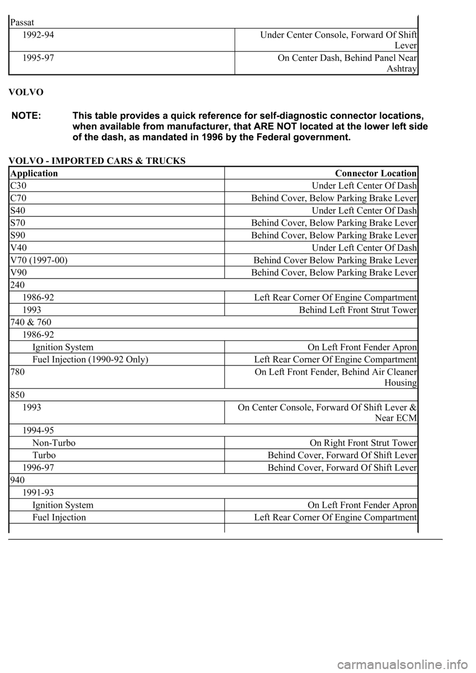
VOLVO
VOLVO - IMPORTED CARS & TRUCKS
Passat
1992-94Under Center Console, Forward Of Shift
Lever
1995-97On Center Dash, Behind Panel Near
Ashtray
ApplicationConnector Location
C30Under Left Center Of Dash
C70Behind Cover, Below Parking Brake Lever
S40Under Left Center Of Dash
S70Behind Cover, Below Parking Brake Lever
S90Behind Cover, Below Parking Brake Lever
V40Under Left Center Of Dash
V70 (1997-00)Behind Cover Below Parking Brake Lever
V90Behind Cover, Below Parking Brake Lever
240
1986-92Left Rear Corner Of Engine Compartment
1993Behind Left Front Strut Tower
740 & 760
1986-92
Ignition SystemOn Left Front Fender Apron
Fuel Injection (1990-92 Only)Left Rear Corner Of Engine Compartment
780On Left Front Fender, Behind Air Cleaner
Housing
850
1993On Center Console, Forward Of Shift Lever &
Near ECM
1994-95
Non-TurboOn Right Front Strut Tower
TurboBehind Cover, Forward Of Shift Lever
1996-97Behind Cover, Forward Of Shift Lever
940
1991-93
Ignition SystemOn Left Front Fender Apron
Fuel InjectionLeft Rear Corner Of Engine Compartment
Page 2419 of 4500
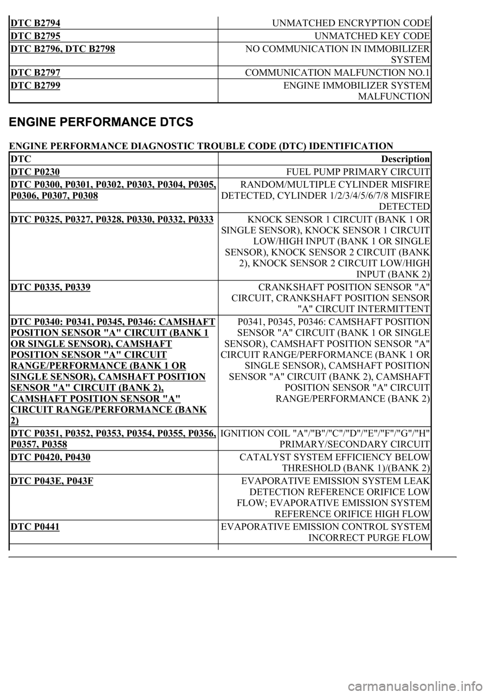
ENGINE PERFORMANCE DIAGNOSTIC TROUBLE CODE (DTC) IDENTIFICATION
DTC B2794 UNMATCHED ENCRYPTION CODE
DTC B2795 UNMATCHED KEY CODE
DTC B2796, DTC B2798 NO COMMUNICATION IN IMMOBILIZER
SYSTEM
DTC B2797 COMMUNICATION MALFUNCTION NO.1
DTC B2799 ENGINE IMMOBILIZER SYSTEM
MALFUNCTION
DTCDescription
DTC P0230 FUEL PUMP PRIMARY CIRCUIT
DTC P0300, P0301, P0302, P0303, P0304, P0305,
P0306, P0307, P0308
RANDOM/MULTIPLE CYLINDER MISFIRE
DETECTED, CYLINDER 1/2/3/4/5/6/7/8 MISFIRE
DETECTED
DTC P0325, P0327, P0328, P0330, P0332, P0333 KNOCK SENSOR 1 CIRCUIT (BANK 1 OR
SINGLE SENSOR), KNOCK SENSOR 1 CIRCUIT
LOW/HIGH INPUT (BANK 1 OR SINGLE
SENSOR), KNOCK SENSOR 2 CIRCUIT (BANK
2), KNOCK SENSOR 2 CIRCUIT LOW/HIGH
INPUT (BANK 2)
DTC P0335, P0339 CRANKSHAFT POSITION SENSOR "A"
CIRCUIT, CRANKSHAFT POSITION SENSOR
"A" CIRCUIT INTERMITTENT
DTC P0340: P0341, P0345, P0346: CAMSHAFT
POSITION SENSOR "A" CIRCUIT (BANK 1
OR SINGLE SENSOR), CAMSHAFT
POSITION SENSOR "A" CIRCUIT
RANGE/PERFORMANCE (BANK 1 OR
SINGLE SENSOR), CAMSHAFT POSITION
SENSOR "A" CIRCUIT (BANK 2),
CAMSHAFT POSITION SENSOR "A"
CIRCUIT RANGE/PERFORMANCE (BANK
2)
P0341, P0345, P0346: CAMSHAFT POSITION
SENSOR "A" CIRCUIT (BANK 1 OR SINGLE
SENSOR), CAMSHAFT POSITION SENSOR "A"
CIRCUIT RANGE/PERFORMANCE (BANK 1 OR
SINGLE SENSOR), CAMSHAFT POSITION
SENSOR "A" CIRCUIT (BANK 2), CAMSHAFT
POSITION SENSOR "A" CIRCUIT
RANGE/PERFORMANCE (BANK 2)
DTC P0351, P0352, P0353, P0354, P0355, P0356,
P0357, P0358
IGNITION COIL "A"/"B"/"C"/"D"/"E"/"F"/"G"/"H"
PRIMARY/SECONDARY CIRCUIT
DTC P0420, P0430 CATALYST SYSTEM EFFICIENCY BELOW
THRESHOLD (BANK 1)/(BANK 2)
DTC P043E, P043F EVAPORATIVE EMISSION SYSTEM LEAK
DETECTION REFERENCE ORIFICE LOW
FLOW; EVAPORATIVE EMISSION SYSTEM
REFERENCE ORIFICE HIGH FLOW
DTC P0441 EVAPORATIVE EMISSION CONTROL SYSTEM
INCORRECT PURGE FLOW
Page 2632 of 4500
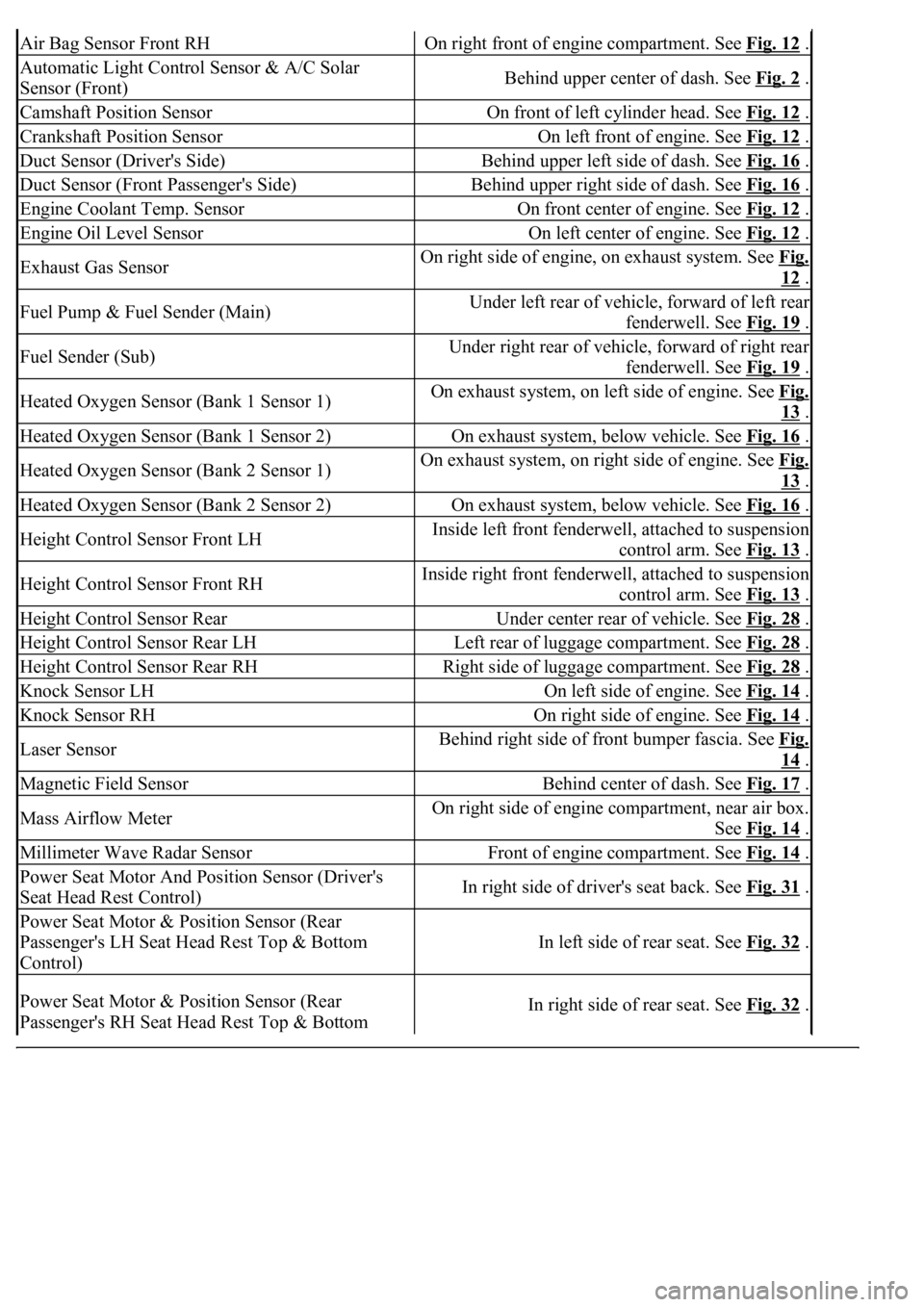
Air Bag Sensor Front RHOn right front of engine compartment. See Fig. 12 .
Automatic Light Control Sensor & A/C Solar
Sensor (Front)Behind upper center of dash. See Fig. 2 .
Camshaft Position SensorOn front of left cylinder head. See Fig. 12 .
Crankshaft Position SensorOn left front of engine. See Fig. 12 .
Duct Sensor (Driver's Side)Behind upper left side of dash. See Fig. 16 .
Duct Sensor (Front Passenger's Side)Behind upper right side of dash. See Fig. 16 .
Engine Coolant Temp. SensorOn front center of engine. See Fig. 12 .
Engine Oil Level SensorOn left center of engine. See Fig. 12 .
Exhaust Gas SensorOn right side of engine, on exhaust system. See Fig.
12 .
Fuel Pump & Fuel Sender (Main)Under left rear of vehicle, forward of left rear
fenderwell. See Fig. 19
.
Fuel Sender (Sub)Under right rear of vehicle, forward of right rear
fenderwell. See Fig. 19
.
Heated Oxygen Sensor (Bank 1 Sensor 1)On exhaust system, on left side of engine. See Fig.
13 .
Heated Oxygen Sensor (Bank 1 Sensor 2)On exhaust system, below vehicle. See Fig. 16 .
Heated Oxygen Sensor (Bank 2 Sensor 1)On exhaust system, on right side of engine. See Fig.
13 .
Heated Oxygen Sensor (Bank 2 Sensor 2)On exhaust system, below vehicle. See Fig. 16 .
Height Control Sensor Front LHInside left front fenderwell, attached to suspension
control arm. See Fig. 13
.
Height Control Sensor Front RHInside right front fenderwell, attached to suspension
control arm. See Fig. 13
.
Height Control Sensor RearUnder center rear of vehicle. See Fig. 28 .
Height Control Sensor Rear LHLeft rear of luggage compartment. See Fig. 28 .
Height Control Sensor Rear RHRight side of luggage compartment. See Fig. 28 .
Knock Sensor LHOn left side of engine. See Fig. 14 .
Knock Sensor RHOn right side of engine. See Fig. 14 .
Laser SensorBehind right side of front bumper fascia. See Fig.
14 .
Magnetic Field SensorBehind center of dash. See Fig. 17 .
Mass Airflow MeterOn right side of engine compartment, near air box.
See Fig. 14
.
Millimeter Wave Radar SensorFront of engine compartment. See Fig. 14 .
Power Seat Motor And Position Sensor (Driver's
Seat Head Rest Control)In right side of driver's seat back. See Fig. 31 .
Power Seat Motor & Position Sensor (Rear
Passenger's LH Seat Head Rest Top & Bottom
Control)
In left side of rear seat. See Fig. 32 .
Power Seat Motor & Position Sensor (Rear
Passenger's RH Seat Head Rest Top & Bottom In right side of rear seat. See Fig. 32 .
Page 2670 of 4500

control ECU, PCM
FC idleDeceleration fuel cut
Idle air control valveIdle speed control
VSV for CCV, Canister close valve VSV for
canister controlEvaporative emissions canister vent valve
VSV for EVAP, Vacuum switching valve assembly
No. 1, EVAP VAV, Purge VSVEvaporative emissions canister purge valve
VSV for pressure switching valve, Bypass VSVEvaporative emission pressure switching valve
Vapor pressure sensor, EVAP pressure sensor,
Evaporative emission control system pressure
sensorFuel tank pressure sensor
Charcoal canisterEvaporative emissions canister
ORVR systemOn-boad refueling vapor recovery system
Intake manifold runner controlIntake manifold tuning system
Intake manifold runner valve, IMRV, IACV (runner
valve)Intake manifold tuning valve
Intake control VSVIntake manifold tuning solenoid valve
AFSAir fuel ratio sensor
O2 sensorHeater oxygen sensor
Oxygen sensor pumping current circuitOxygen sensor output signal
Oxygen sensor reference ground circuitOxygen sensor signal ground
Accel position sensorAccelerator pedal position sensor
Throttle actuator control motor, Actuator control
motor, Electronic throttle motor, Throttle control
motorElectronic throttle actuator
Electronic throttle control system, Throttle actuator
control systemElectronic throttle control system
Throttle/pedal position sensor, Throttle/pedal
position switch, Throttle position sensor/switchThrottle position sensor
Turbo press sensorTurbocharger pressure sensor
Turbo VSVTurbocharger pressure control solenoid valve
P/S pressure switchPower-steering pressure switch
VSV for ACMActive control engine mount
Speed sensor, Vehicle speed sensor "A", Speed
sensor for skid control ECUVehicle speed sensor
ATF temperature sensor, Trans, fluid temp, sensor,
ATF temperature sensor "A"Transmission fluid temperature sensor
Electronic controlled automatic transmission, ECTElectronically controlled automatic
Intermediate shaft speed sensor "A"Counter gear speed sensor
Part and system nameDefinition
Output speed sensorOutput shaft speed sensor
<002c00510053005800570003005600530048004800470003005600480051005600520055000f0003002c005100530058005700030057005800550045004c005100480003005600530048004800470003005600480051005600520055000300050024000500
0f0003[
Speed sensor (NT), Turbine speed sensorInput turbine speed sensor
Page 2676 of 4500
SYSTEM DESCRIPTION
1.SYSTEM DESCRIPTION
a. The ECT (Electronic controlled automatic transmission) is an automatic transmission that
electronically controls shift timing using the ECM. The ECM detects electrical signals that indicate
engine and driving conditions, and controls the shift point, based on driver habits and road
conditions. As a result, fuel efficiency and power transmission performance are improved.
<0036004b004c0049005700030056004b00520046004e0003004b00440056000300450048004800510003005500480047005800460048004700030045005c0003004600520051005700550052004f004f004c0051004a00030057004b004800030048005100
4a004c00510048000300440051004700030057005500440051[smission simultaneously. In
addition, the ECT has features such as follows:
Diagnostic function.
Fail-safe function when a malfunction occurs.
HOW TO PROCEED WITH TROUBLESHOOTING
HINT:
The ECM of this system is connected to the CAN and multiplex communication system. Therefore,
before starting troubleshooting, make sure to check that there is no trouble in the CAN and multiplex
communication system.
<0037004b00480003004b0044005100470010004b0048004f0047000300570048005600570048005500030046004400510003004500480003005800560048004700030044005700030056005700480053005600030016000f00030017000f00030019000f00
030044005100470003001c00110003[
1.Vehicle Brought to Workshop
2.Customer Problem Analysis (See CUSTOMER PROBLEM ANALYSIS CHECK
)
3.Connect the OBD II scan tool or hand-held tester to DLC3
4.Check and Clear DTCs and Freeze Frame Data (See DTC CHECK/CLEAR
)
5.Visual Inspection
6.Setting the Check Mode Diagnosis (See CHECK MODE PROCEDURE
)
7.Problem Symptom Confirmation (See ROAD TEST
)
Symptom does not occur: Go to step 8
Symptom occurs: Go to step 9
8.Symptom Simulation (See HOW TO PROCEED WITH TROUBLESHOOTING
)
9.DTC Check (See DTC CHECK/CLEAR
)
DTC is not output: Go to step 10
DTC is output: Go to step 17
10.Basic Inspection (See ADJUSTMENT
- AUTOMATIC TRANSMISSION FLUID ,
ADJUSTMENT
- PARK/NEUTRAL POSITION SWITCH ASSY and ADJUSTMENT -
FLOOR SHIFT ASSY
)