height adjustment LEXUS LS430 2003 Factory Repair Manual
[x] Cancel search | Manufacturer: LEXUS, Model Year: 2003, Model line: LS430, Model: LEXUS LS430 2003Pages: 4500, PDF Size: 87.45 MB
Page 1968 of 4500
a. Preparation for adjusting the radar beam axis
1. Adjust the tire pressure properly (see INSPECTION
).
2. Luggage in the vehicle, such as in the trunk, should be unloaded.
b. Adjust the standard vehicle height (vehicle with air suspension) (see INSPECTION
)
c. Adjustment in vertical direction of the millimeter wave radar sensor.
1. Remove dust and oil on the level rack of the millimeter wave radar sensor.
2. Set the specified level on the center of the level rack of the millimeter wave radar sensor.
Fig. 21: Setting Specified Level
Courtesy of TOYOTA MOTOR SALES, U.S.A., INC.
3. Using a hexagon wrench, turn and adjust screw A for vertical adjustment of the millimeter
wave radar sensor so that the air bubble is within the red frame on the level.
Standard:
Adjustable range within the red frame of the level is ± 0.2°.
Page 1970 of 4500
Fig. 23: Adjustment Direction Chart
Courtesy of TOYOTA MOTOR SALES, U.S.A., INC.
d. Adjust the reflector height
1. Adjust the reflector so that the center of the SST reflector is the same height as the millimeter
wave radar sensor.
SST 09870-60000 (09870-60010, 09870-60040)
HINT:
Prepare a 10 m (32.81 ft) string, with a sharp-pointed weight (plumb bob), and a 5 m (16.41 ft) tape
measure.
Page 2177 of 4500
a. Fill the rear differential carrier assy with differential gear oil equivalent.
Oil type: Differential synthetic gear oil GL-5 75W-90 or equivalent
Capacity: 1.35 +/- 0.05 liters (1.43 +/- 0.05 US qts, 1.19 +/- 0.04 Imp. qts)
67.INSPECT DIFFERENTIAL OIL (SEE ADJUSTMENT
)
68.INSTALL REAR DIFFERENTIAL FILLER PLUG
a. Using a hexagon wrench (10 mm), install the filler plug with a new gasket.
Torque: 49 N.m (500 kgf.cm, 36 ft.lbf)
69.INSTALL REAR DRIVE SHAFT ASSY LH (SEE REPLACEMENT
)
70.INSTALL REAR DRIVE SHAFT ASSY RH
HINT:
Installation procedure of the RH side is the same as that of the LH side.
71.INSTALL FRONT FLOOR HEAT INSULATOR NO.1
a. Install the front floor heat insulator No.1 with the 4 bolts.
Torque: 5.4 N.m (55 kgf.cm, 48 in..lbf)
72.INSTALL REAR WHEEL
a. Install the rear wheel with the 5 nuts.
Torque: 103 N.m (1,050 kgf.cm, 76 ft.lbf)
73. Install the ornament with the 10 bolts.
Torque: 20 N.m (204 kgf.cm, 15 ft.lbf)
74.INSTALL PROPELLER W/CENTER BEARING SHAFT ASSY (SEE OVERHAUL
)
75.FULLY TIGHTEN CENTER SUPPORT BEARING ASSY NO.1 (SEE OVERHAUL
)
SST 09922-10010
76.INSPECT AND ADJUST NO.2 AND NO.3 JOINT ANGLE (SEE OVERHAUL
)
77.INSTALL PROPELLER SHAFT HEAT INSULATOR (SEE OVERHAUL
)
78.INSTALL EXHAUST PIPE ASSY (SEE REPLACEMENT
)
79.INSTALL OXYGEN SENSOR (SEE REPLACEMENT
)
80.INSPECT AND ADJUST REAR WHEEL ALIGNMENT (SEE ADJUSTMENT
)
81.ADJUST VEHICLE HEIGHT (W/ AIR SUSPENSION) (SEE ON
-VEHICLE INSPECTION )
82.INSPECT HEADLIGHT AIM ONLY (SEE ADJUSTMENT
)
83.CHECK ABS SPEED SENSOR SIGNAL (SEE TEST MODE PROCEDURE
)
84.INSPECT AIR LEAK (W/ AIR SUSPENSION) (SEE REPLACEMENT
)
HINT:
Perform this operation onl
y when the rear differential mount cushion is replaced.
Page 2391 of 4500
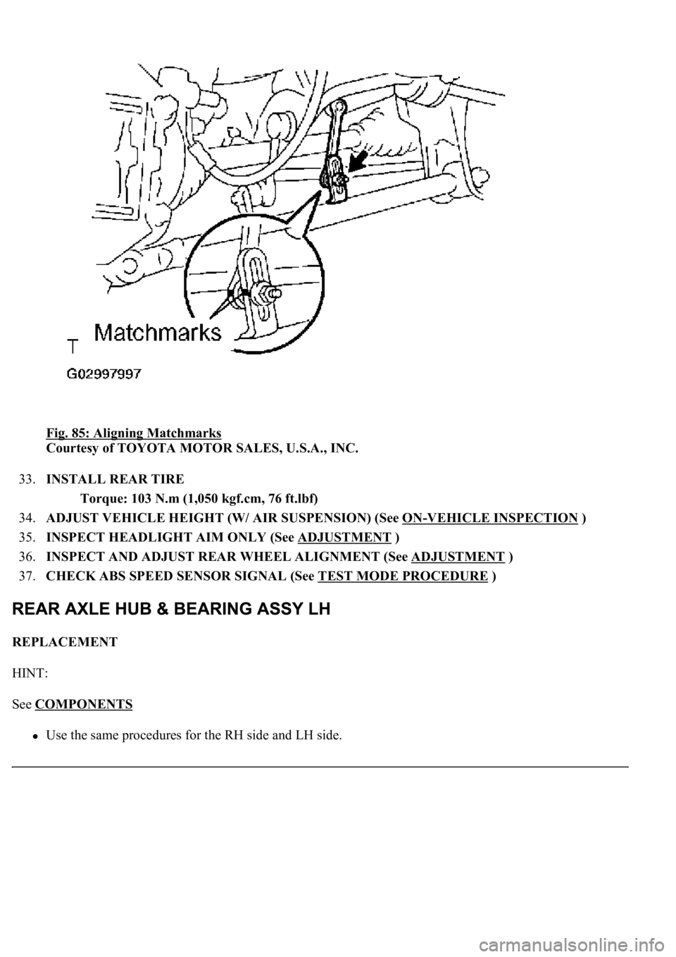
Fig. 85: Aligning Matchmarks
Courtesy of TOYOTA MOTOR SALES, U.S.A., INC.
33.INSTALL REAR TIRE
Torque: 103 N.m (1,050 kgf.cm, 76 ft.lbf)
34.ADJUST VEHICLE HEIGHT (W/ AIR SUSPENSION) (See ON
-VEHICLE INSPECTION )
35.INSPECT HEADLIGHT AIM ONLY (See ADJUSTMENT
)
36.INSPECT AND ADJUST REAR WHEEL ALIGNMENT (See ADJUSTMENT
)
37.CHECK ABS SPEED SENSOR SIGNAL (See TEST MODE PROCEDURE
)
REPLACEMENT
HINT:
See COMPONENTS
<00380056004800030057004b00480003005600440050004800030053005500520046004800470058005500480056000300490052005500030057004b004800030035002b00030056004c0047004800030044005100470003002f002b00030056004c004700
4800110003[
Page 2407 of 4500
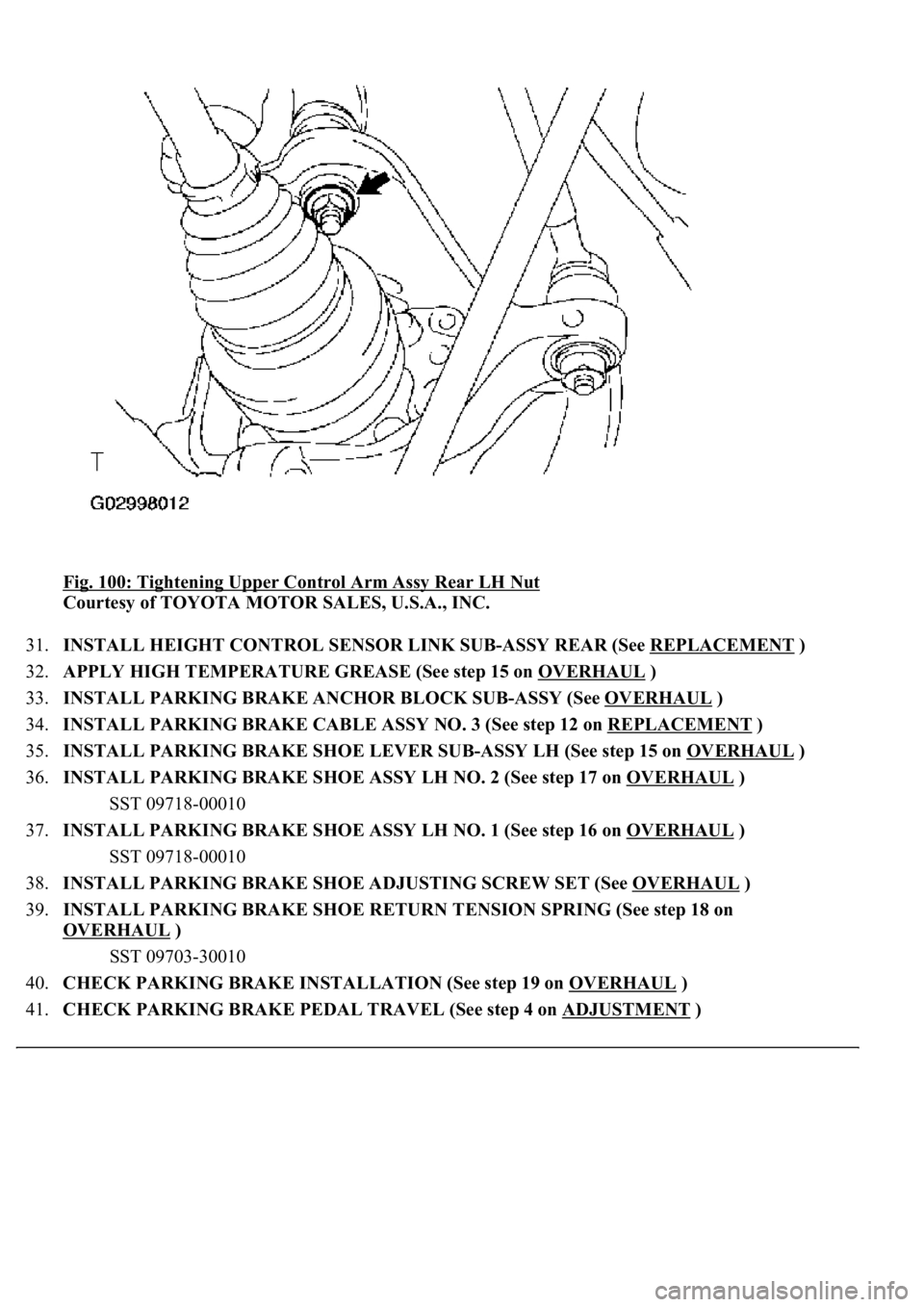
Fig. 100: Tightening Upper Control Arm Assy Rear LH Nut
Courtesy of TOYOTA MOTOR SALES, U.S.A., INC.
31.INSTALL HEIGHT CONTROL SENSOR LINK SUB-ASSY REAR (See REPLACEMENT
)
32.APPLY HIGH TEMPERATURE GREASE (See step 15 on OVERHAUL
)
33.INSTALL PARKING BRAKE ANCHOR BLOCK SUB-ASSY (See OVERHAUL
)
34.INSTALL PARKING BRAKE CABLE ASSY NO. 3 (See step 12 on REPLACEMENT
)
35.INSTALL PARKING BRAKE SHOE LEVER SUB-ASSY LH (See step 15 on OVERHAUL
)
36.INSTALL PARKING BRAKE SHOE ASSY LH NO. 2 (See step 17 on OVERHAUL
)
SST 09718-00010
37.INSTALL PARKING BRAKE SHOE ASSY LH NO. 1 (See step 16 on OVERHAUL
)
SST 09718-00010
38.INSTALL PARKING BRAKE SHOE ADJUSTING SCREW SET (See OVERHAUL
)
39.INSTALL PARKING BRAKE SHOE RETURN TENSION SPRING (See step 18 on
OVERHAUL
)
SST 09703-30010
40.CHECK PARKING BRAKE INSTALLATION (See step 19 on OVERHAUL
)
41.CHECK PARKING BRAKE PEDAL TRAVEL (See step 4 on ADJUSTMENT
)
Page 2408 of 4500
42.ADJUST PARKING BRAKE PEDAL TRAVEL (See step 5 on ADJUSTMENT )
43.INSTALL SPEED SENSOR REAR LH
a. Install the speed sensor with the bolt.
Torque: 8.0 N.m (82 kgf.cm, 71 in.lbf)
44.INSTALL REAR DISC (See step 16 on OVERHAUL
)
45.ADJUST PARKING BRAKE SHOE CLEARANCE (See step 21 on OVERHAUL
)
46.INSTALL REAR DISC BRAKE CALIPER ASSY LH (See step 20 on REPLACEMENT
)
47.INSTALL REAR AXLE SHAFT NUT (See REPLACEMENT
)
48.INSPECT AXLE HUB BEARING LOOSENESS (See ON
-VEHICLE INSPECTION )
49.INSPECT AXLE HUB BEARING RUNOUT (See ON
-VEHICLE INSPECTION )
50.STABILIZE SUSPENSION (See step 23 on REPLACEMENT
)
51.FULLY TIGHTEN SHOCK ABSORBER ASSY REAR LH
a. Fully tighten the shock absorber assy LH with the new nut.
Torque: 70 N.m (714 kgf.cm, 52 ft.lbf)
52.INSTALL REAR TIRE
Torque: 103 N.m (1,050 kgf.cm, 76 ft.lbf)
53.ADJUST VEHICLE HEIGHT (W/ AIR SUSPENSION) (See ON
-VEHICLE INSPECTION )
54.INSPECT HEADLIGHT AIM ONLY (See ADJUSTMENT
)
55.INSPECT AND ADJUST REAR WHEEL ALIGNMENT (See ADJUSTMENT
)
56.CHECK ABS SPEED SENSOR SIGNAL (See TEST MODE PROCEDURE
)
REPLACEMENT
HINT:
See COMPONENTS
Use the same procedures for the RH side and LH side.
The procedures listed below are for the LH side.
1.REMOVE REAR TIRE
2.REMOVE REAR DISC BRAKE CALIPER ASSY LH (See REPLACEMENT
)
3.REMOVE REAR DISC (See step 15 on OVERHAUL
)
4.REMOVE REAR AXLE LH HUB BOLT
a. Using SST and a screwdriver or an equivalent to hold, remove the hub bolt.
SST 09628-10011
Page 3916 of 4500
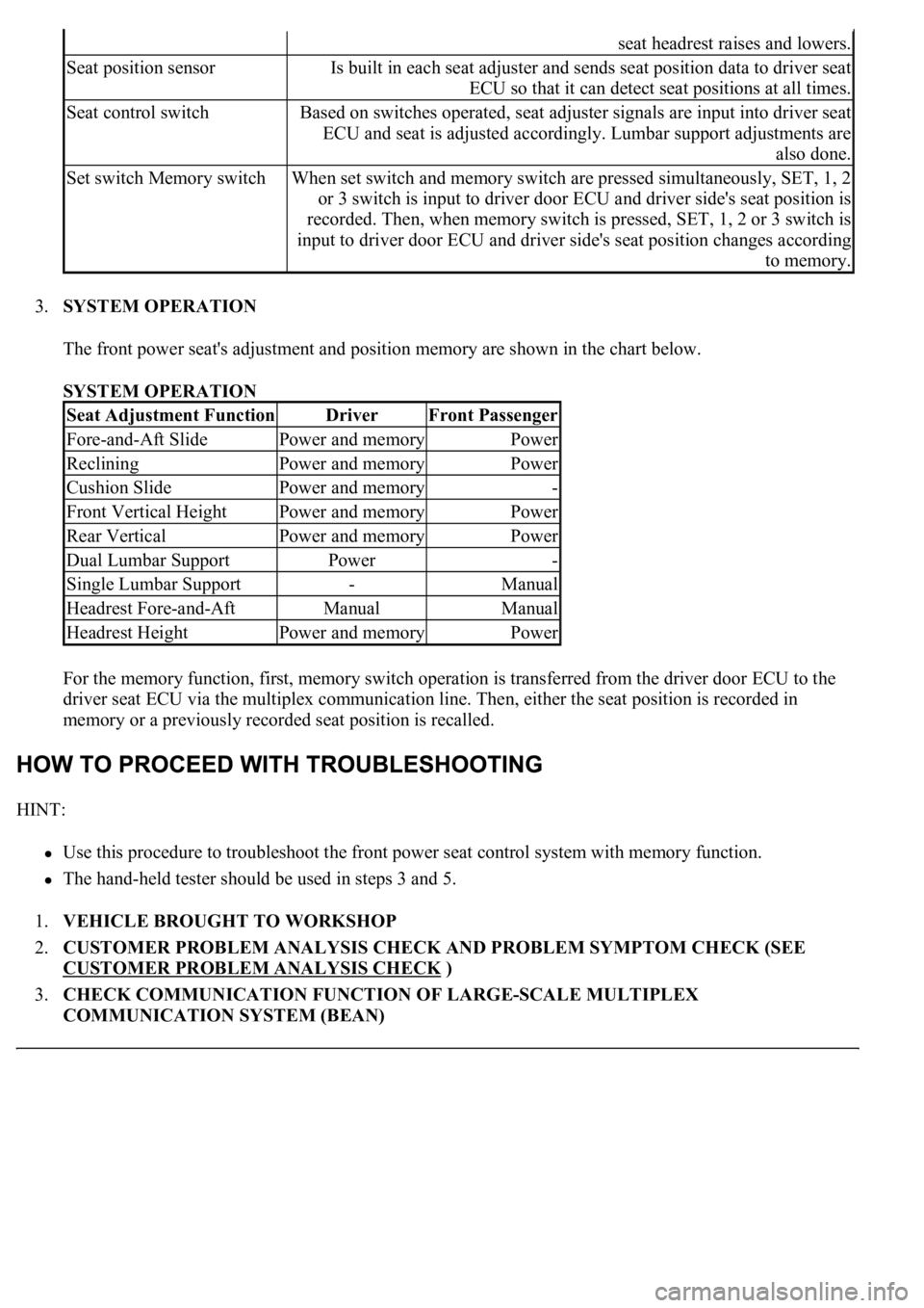
3.SYSTEM OPERATION
The front power seat's adjustment and position memory are shown in the chart below.
SYSTEM OPERATION
For the memory function, first, memory switch operation is transferred from the driver door ECU to the
driver seat ECU via the multiplex communication line. Then, either the seat position is recorded in
memory or a previously recorded seat position is recalled.
HINT:
Use this procedure to troubleshoot the front power seat control system with memory function.
<0037004b00480003004b0044005100470010004b0048004f0047000300570048005600570048005500030056004b00520058004f0047000300450048000300580056004800470003004c005100030056005700480053005600030016000300440051004700
030018001100030003[
1.VEHICLE BROUGHT TO WORKSHOP
2.CUSTOMER PROBLEM ANALYSIS CHECK AND PROBLEM SYMPTOM CHECK (SEE
CUSTOMER PROBLEM ANALYSIS CHECK
)
3.CHECK COMMUNICATION FUNCTION OF LARGE-SCALE MULTIPLEX
COMMUNICATION SYSTEM (BEAN)
seat headrest raises and lowers.
Seat position sensorIs built in each seat adjuster and sends seat position data to driver seat
ECU so that it can detect seat positions at all times.
Seat control switchBased on switches operated, seat adjuster signals are input into driver seat
ECU and seat is adjusted accordingly. Lumbar support adjustments are
also done.
Set switch Memory switchWhen set switch and memory switch are pressed simultaneously, SET, 1, 2
or 3 switch is input to driver door ECU and driver side's seat position is
recorded. Then, when memory switch is pressed, SET, 1, 2 or 3 switch is
input to driver door ECU and driver side's seat position changes according
to memory.
Seat Adjustment FunctionDriverFront Passenger
Fore-and-Aft SlidePower and memoryPower
RecliningPower and memoryPower
Cushion SlidePower and memory-
Front Vertical HeightPower and memoryPower
Rear VerticalPower and memoryPower
Dual Lumbar SupportPower-
Single Lumbar Support-Manual
Headrest Fore-and-AftManualManual
Headrest HeightPower and memoryPower
Page 3998 of 4500
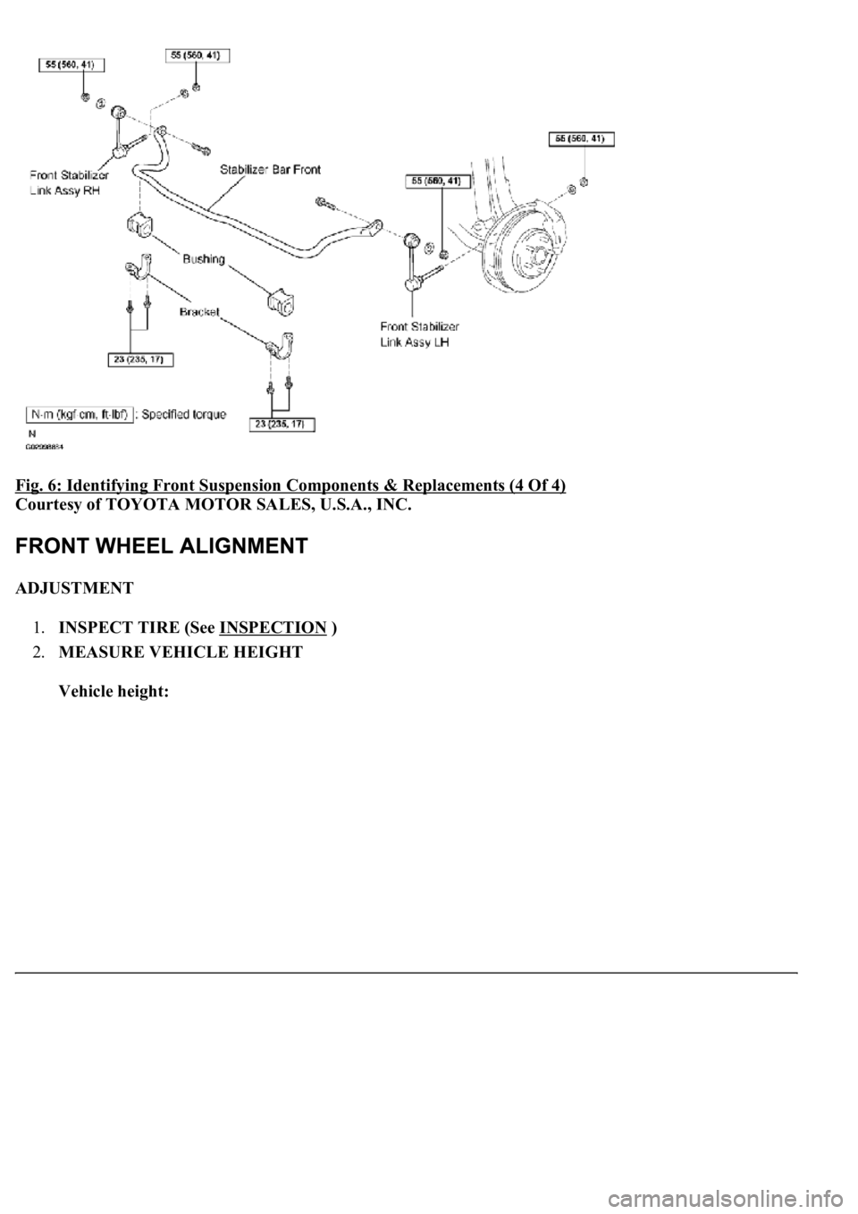
Fig. 6: Identifying Front Suspension Components & Replacements (4 Of 4)
Courtesy of TOYOTA MOTOR SALES, U.S.A., INC.
ADJUSTMENT
1.INSPECT TIRE (See INSPECTION
)
2.MEASURE VEHICLE HEIGHT
Vehicle height:
Page 4023 of 4500
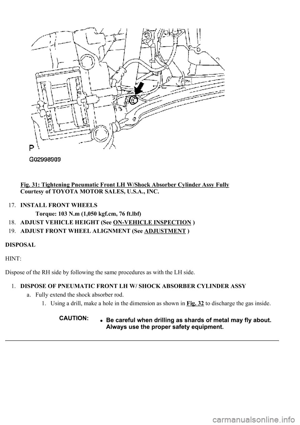
Fig. 31: Tightening Pneumatic Front LH W/Shock Absorber Cylinder Assy Fully
Courtesy of TOYOTA MOTOR SALES, U.S.A., INC.
17.INSTALL FRONT WHEELS
Torque: 103 N.m (1,050 kgf.cm, 76 ft.lbf)
18.ADJUST VEHICLE HEIGHT (See ON
-VEHICLE INSPECTION )
19.ADJUST FRONT WHEEL ALIGNMENT (See ADJUSTMENT
)
DISPOSAL
HINT:
Dispose of the RH side by following the same procedures as with the LH side.
1.DISPOSE OF PNEUMATIC FRONT LH W/ SHOCK ABSORBER CYLINDER ASSY
a. Fully extend the shock absorber rod.
1. Using a drill, make a hole in the dimension as shown in Fig. 32
to discharge the gas inside.
Page 4043 of 4500
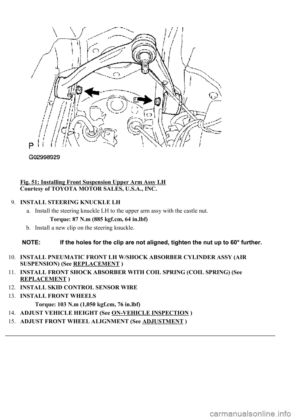
Fig. 51: Installing Front Suspension Upper Arm Assy LH
Courtesy of TOYOTA MOTOR SALES, U.S.A., INC.
9.INSTALL STEERING KNUCKLE LH
a. Install the steering knuckle LH to the upper arm assy with the castle nut.
Torque: 87 N.m (885 kgf.cm, 64 in.lbf)
b. Install a new clip on the steering knuckle.
10.INSTALL PNEUMATIC FRONT LH W/SHOCK ABSORBER CYLINDER ASSY (AIR
SUSPENSION) (See REPLACEMENT
)
11.INSTALL FRONT SHOCK ABSORBER WITH COIL SPRING (COIL SPRING) (See
REPLACEMENT
)
12.INSTALL SKID CONTROL SENSOR WIRE
13.INSTALL FRONT WHEELS
Torque: 103 N.m (1,050 kgf.cm, 76 in.lbf)
14.ADJUST VEHICLE HEIGHT (See ON
-VEHICLE INSPECTION )
15.ADJUST FRONT WHEEL ALIGNMENT (See ADJUSTMENT
)