LEXUS LS500 2019 Owners Manual
Manufacturer: LEXUS, Model Year: 2019, Model line: LS500, Model: LEXUS LS500 2019Pages: 512, PDF Size: 9.71 MB
Page 461 of 512
4618-1. Specifications
LS500_OM_(U)_1810 8
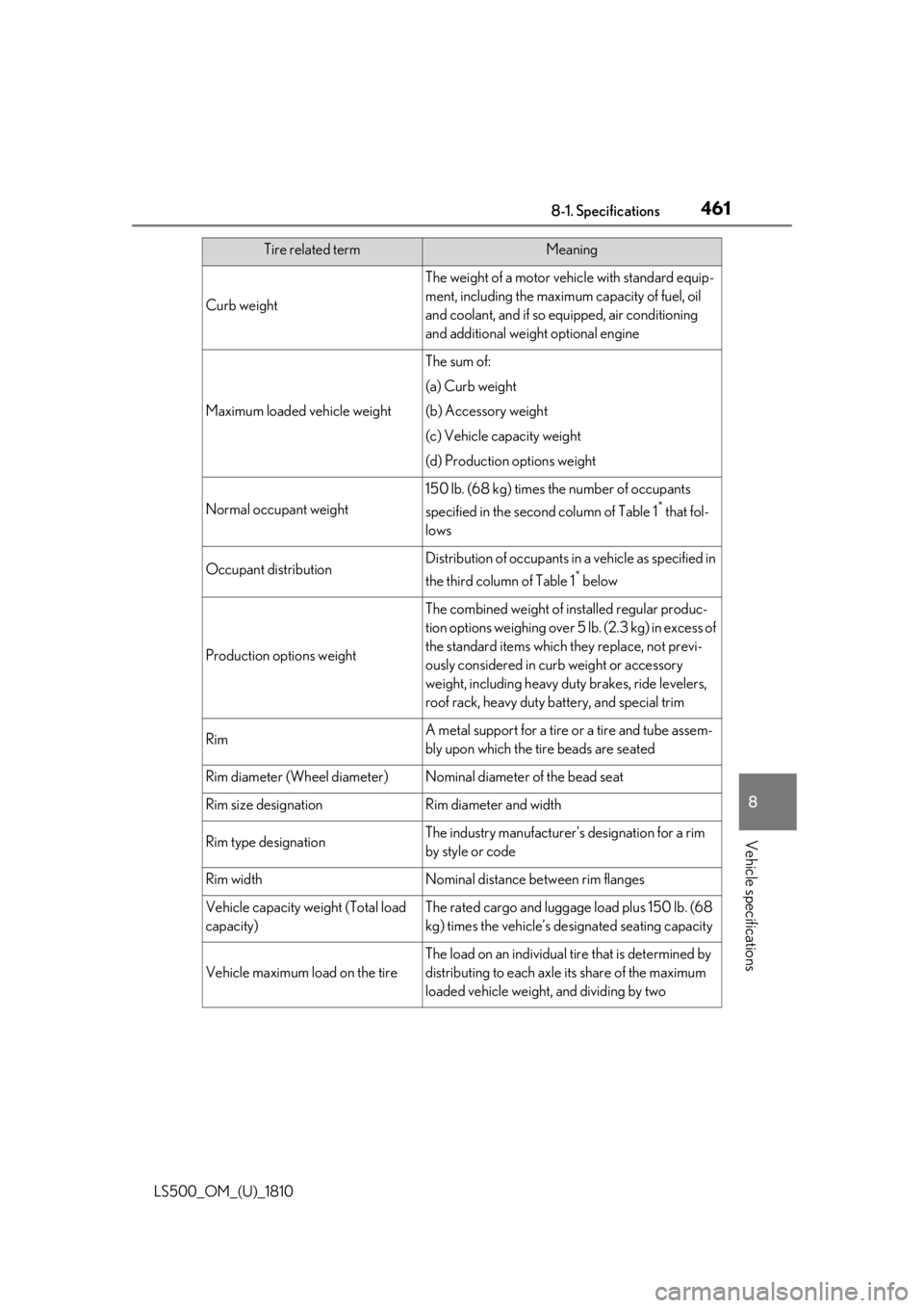
Vehicle specifications Curb weight The weight of a motor vehicle with standard equip-
ment, including the maximum capacity of fuel, oil
and coolant, and if so equipped, air conditioning
and additional weight optional engine
Maximum loaded vehicle weight The sum of:
(a) Curb weight
(b) Accessory weight
(c) Vehicle capacity weight
(d) Production options weight
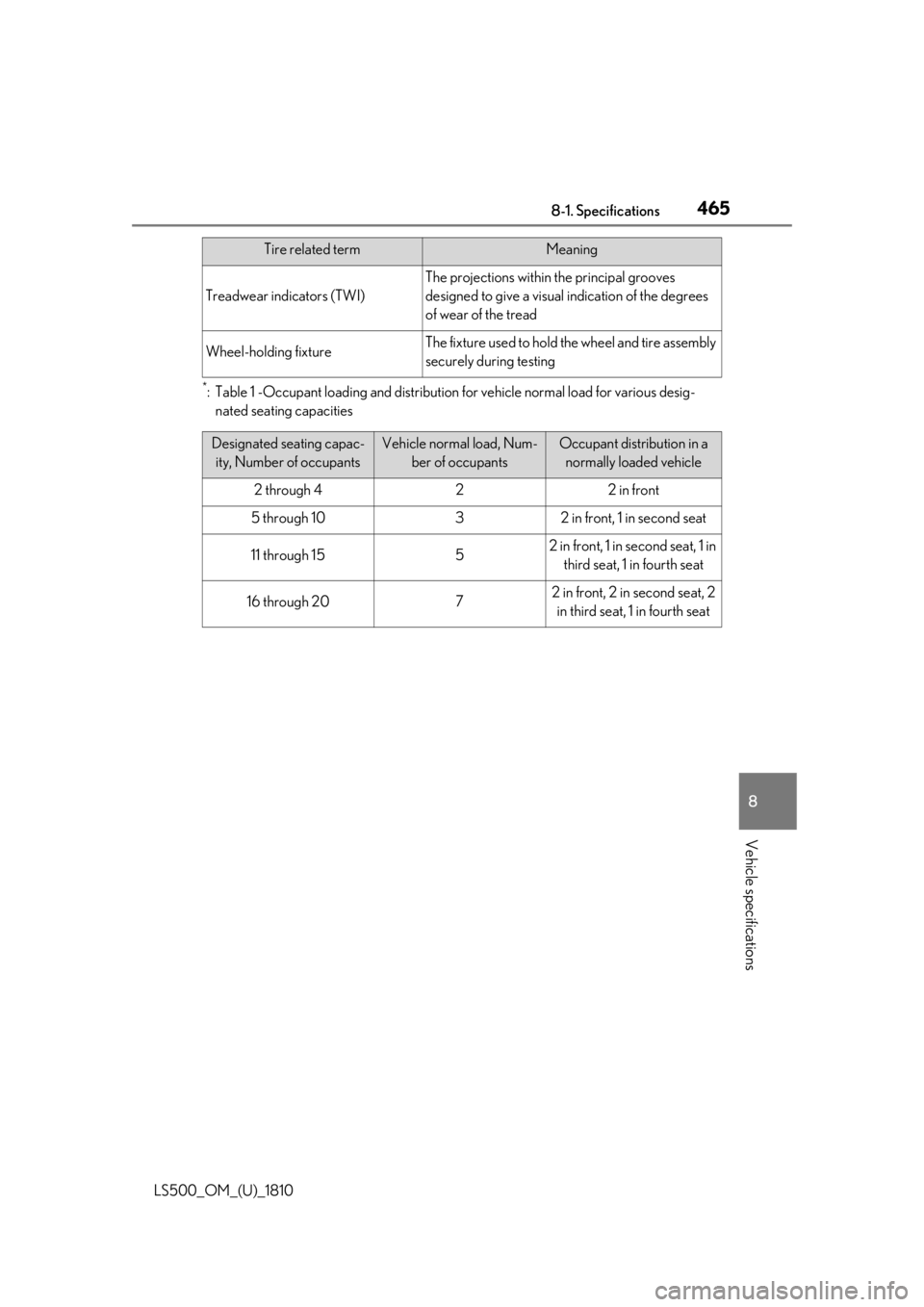
Normal occupant weight 150 lb. (68 kg) times the number of occupants
specified in the second column of Table 1 *
that fol-
lows
Occupant distribution Distribution of occupants in a vehicle as specified in
the third column of Table 1 *
below
Production options weight The combined weight of installed regular produc-
tion options weighing over 5 lb. (2.3 kg) in excess of
the standard items which they replace, not previ-
ously considered in curb weight or accessory
weight, including heavy duty brakes, ride levelers,
roof rack, heavy duty battery, and special trim
Rim A metal support for a tire or a tire and tube assem-
bly upon which the tire beads are seated
Rim diameter (Wheel diameter) Nominal diameter of the bead seat
Rim size designation Rim diameter and width
Rim type designation The industry manufacturer’s designation for a rim
by style or code
Rim width Nominal distance between rim flanges
Vehicle capacity weight (Total load
capacity) The rated cargo and luggage load plus 150 lb. (68
kg) times the vehicle’s de signated seating capacity
Vehicle maximum load on the tire The load on an individual ti re that is determined by
distributing to each axle its share of the maximum
loaded vehicle weight, and dividing by twoTire related term Meaning
Page 462 of 512
462 8-1. Specifications
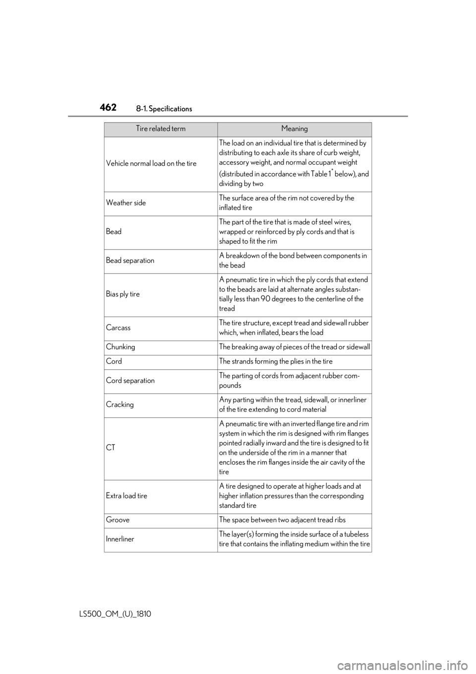
LS500_OM_(U)_1810 Vehicle normal load on the tire The load on an individual ti re that is determined by
distributing to each axle its share of curb weight,
accessory weight, and normal occupant weight
(distributed in accor dance with Table 1 *
below), and
dividing by two
Weather side The surface area of the rim not covered by the
inflated tire
Bead The part of the tire that is made of steel wires,
wrapped or reinforced by ply cords and that is
shaped to fit the rim
Bead separation A breakdown of the bond between components in
the bead
Bias ply tire A pneumatic tire in which the ply cords that extend
to the beads are laid at alternate angles substan-
tially less than 90 degrees to the centerline of the
tread
Carcass The tire structure, except tread and sidewall rubber
which, when inflated, bears the load
Chunking The breaking away of pieces of the tread or sidewall
Cord The strands forming the plies in the tire
Cord separation The parting of cords from adjacent rubber com-
pounds
Cracking Any parting within the tread, sidewall, or innerliner
of the tire extending to cord material
CT A pneumatic tire with an inverted flange tire and rim
system in which the rim is designed with rim flanges
pointed radially inward and the tire is designed to fit
on the underside of the rim in a manner that
encloses the rim flanges inside the air cavity of the
tire
Extra load tire A tire designed to operat e at higher loads and at
higher inflation pressures than the corresponding
standard tire
Groove The space between two adjacent tread ribs
Innerliner The layer(s) forming the in side surface of a tubeless
tire that contains the inflating medium within the tireTire related term Meaning
Page 463 of 512
4638-1. Specifications
LS500_OM_(U)_1810 8
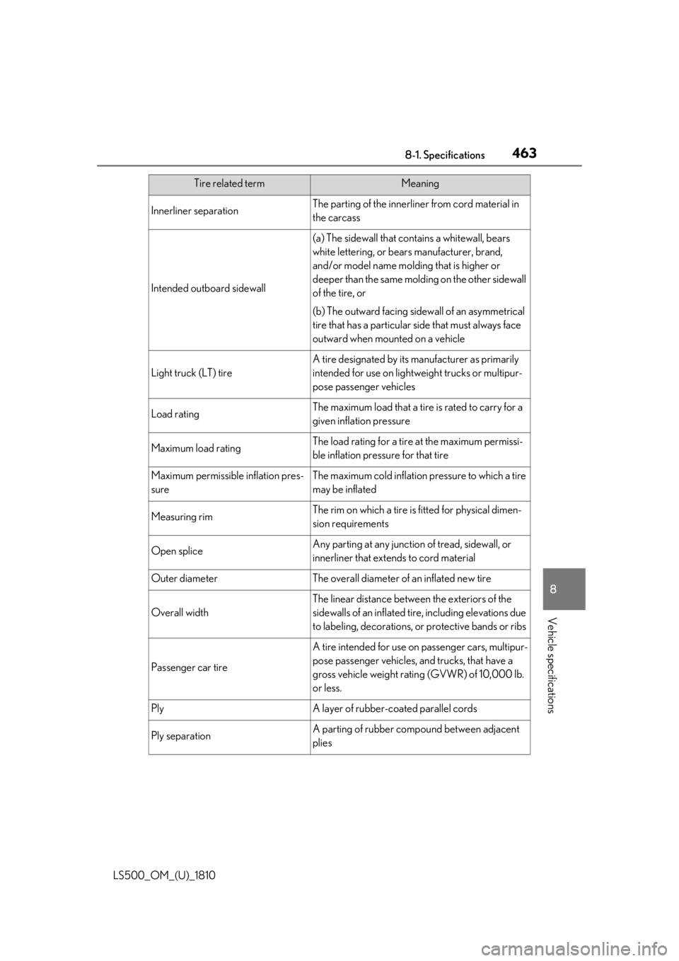
Vehicle specifications Innerliner separation The parting of the innerliner from cord material in
the carcass
Intended outboard sidewall (a) The sidewall that contains a whitewall, bears
white lettering, or bear s manufacturer, brand,
and/or model name molding that is higher or
deeper than the same molding on the other sidewall
of the tire, or
(b) The outward facing side wall of an asymmetrical
tire that has a particular side that must always face
outward when mounted on a vehicle
Light truck (LT) tire A tire designated by its manufacturer as primarily
intended for use on lightwe ight trucks or multipur-
pose passenger vehicles
Load rating The maximum load that a tire is rated to carry for a
given inflation pressure
Maximum load rating The load rating for a tire at the maximum permissi-
ble inflation pressure for that tire
Maximum permissible inflation pres-
sure The maximum cold inflation pressure to which a tire
may be inflated
Measuring rim The rim on which a tire is fitted for physical dimen-
sion requirements
Open splice Any parting at any junction of tread, sidewall, or
innerliner that extends to cord material
Outer diameter The overall diameter of an inflated new tire
Overall width The linear distance between the exteriors of the
sidewalls of an inflated tire, including elevations due
to labeling, decorations, or protective bands or ribs
Passenger car tire A tire intended for use on passenger cars, multipur-
pose passenger vehicles, and trucks, that have a
gross vehicle weight rating (GVWR) of 10,000 lb.
or less.
Ply A layer of rubber-c oated parallel cords
Ply separation A parting of rubber compound between adjacent
pliesTire related term Meaning
Page 464 of 512
464 8-1. Specifications
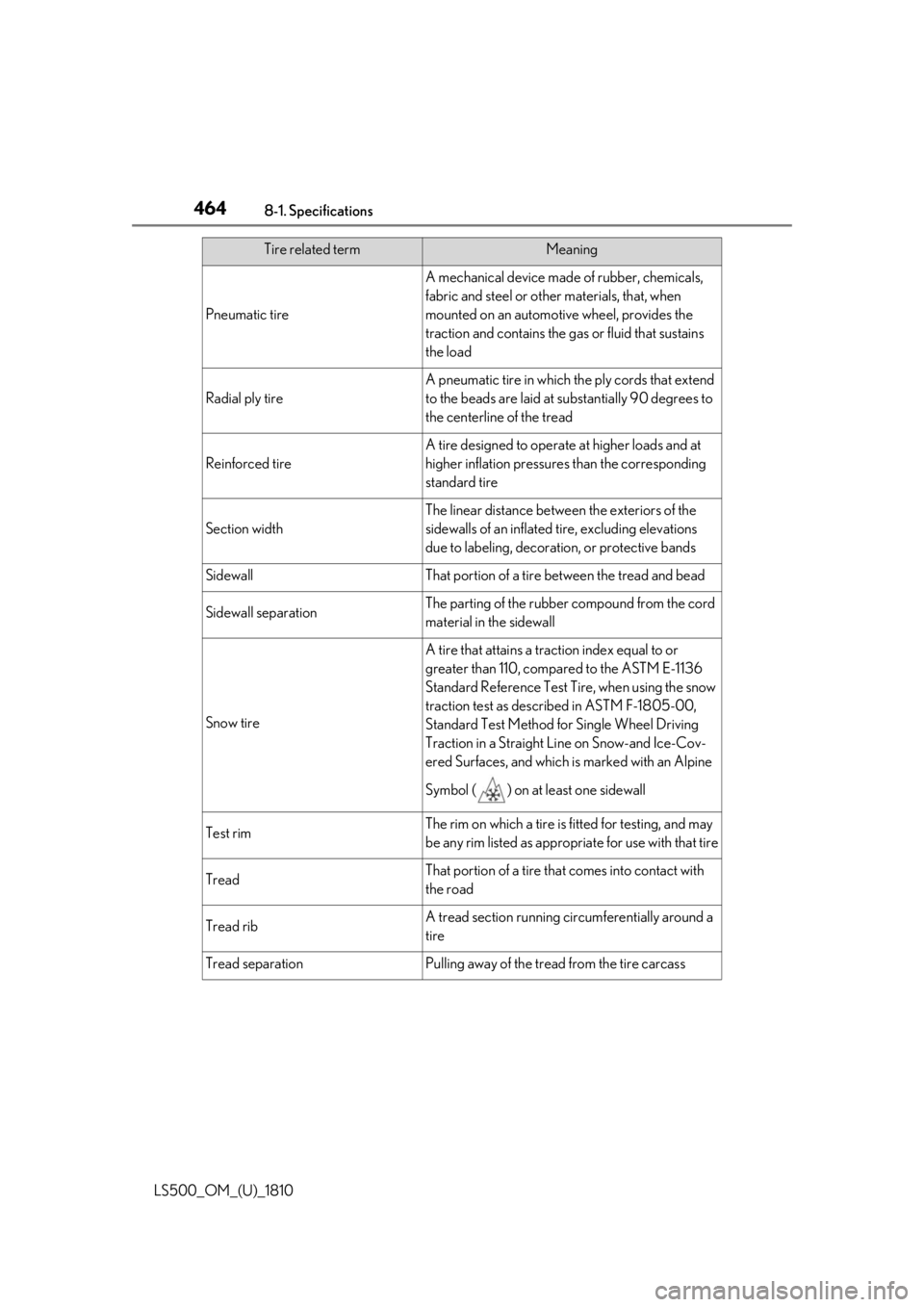
LS500_OM_(U)_1810 Pneumatic tire A mechanical device made of rubber, chemicals,
fabric and steel or other materials, that, when
mounted on an automotive wheel, provides the
traction and contains the gas or fluid that sustains
the load
Radial ply tire A pneumatic tire in which the ply cords that extend
to the beads are laid at su bstantially 90 degrees to
the centerline of the tread
Reinforced tire A tire designed to operat e at higher loads and at
higher inflation pressures than the corresponding
standard tire
Section width The linear distance between the exteriors of the
sidewalls of an inflated tire, excluding elevations
due to labeling, decoration, or protective bands
Sidewall That portion of a tire between the tread and bead
Sidewall separation The parting of the rubber compound from the cord
material in the sidewall
Snow tire A tire that attains a traction index equal to or
greater than 110, compared to the ASTM E-1136
Standard Referenc e Test Tire, when using the snow
traction test as described in ASTM F-1805-00,
Standard Test Method fo r Single Wheel Driving
Traction in a Straight Li ne on Snow-and Ice-Cov-
ered Surfaces, and which is marked with an Alpine
Symbol ( ) on at least one sidewall
Test rim The rim on which a tire is fitted for testing, and may
be any rim listed as appropriate for use with that tire
Tread That portion of a tire that comes into contact with
the road
Tread rib A tread section running ci rcumferentially around a
tire
Tread separation Pulling away of the tread from the tire carcassTire related term Meaning
Page 465 of 512
4658-1. Specifications
LS500_OM_(U)_1810 8
Vehicle specifications *
: Table 1 -Occupant loading and distribution for vehicle normal load for various desig-
nated seating capacitiesTreadwear indicators (TWI) The projections within the principal grooves
designed to give a visual indication of the degrees
of wear of the tread
Wheel-holding fixture The fixture used to hold the wheel and tire assembly
securely during testingTire related term Meaning
Designated seating capac-
ity, Number of occupants Vehicle normal load, Num-
ber of occupants Occupant distribution in a
normally loaded vehicle
2 through 4 2 2 in front
5 through 10 3 2 in front, 1 in second seat
11 through 15 5 2 in front, 1 in second seat, 1 in
third seat, 1 in fourth seat
16 through 20 7 2 in front, 2 in second seat, 2
in third seat, 1 in fourth seat
Page 466 of 512
466 8-2. Customization
LS500_OM_(U)_1810 8-2.Customization
■
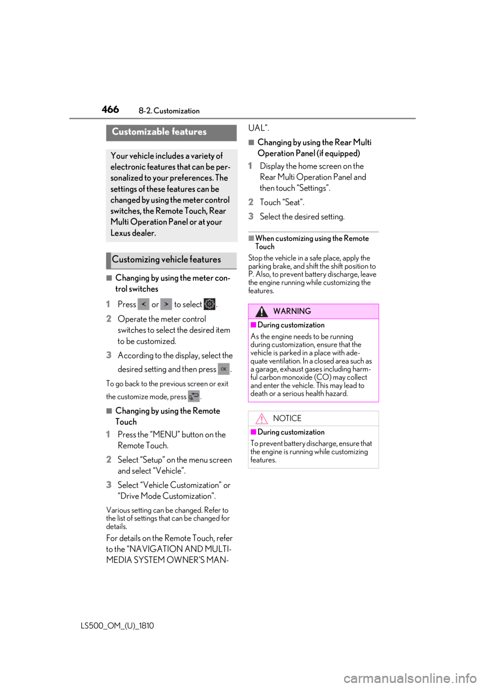
Changing by using the meter con-
trol switches
1 Press or to select .
2 Operate the meter control
switches to select the desired item
to be customized.
3 According to the display, select the
desired setting and then press .To go back to the previous screen or exit
the customize mode, press .
■
Changing by using the Remote
Touch
1 Press the “MENU” button on the
Remote Touch.
2 Select “Setup” on the menu screen
and select “Vehicle”.
3 Select “Vehicle Customization” or
“Drive Mode Customization”.Various setting can be changed. Refer to
the list of settings that can be changed for
details.
For details on the Remote Touch, refer
to the “NAVIGATION AND MULTI-
MEDIA SYSTEM OWNER’S MAN- UAL”. ■
Changing by using the Rear Multi
Operation Panel (if equipped)
1 Display the home screen on the
Rear Multi Operation Panel and
then touch “Settings”.
2 Touch “Seat”.
3 Select the desired setting. ■
When customizing using the Remote
Touch
Stop the vehicle in a safe place, apply the
parking brake, and shift the shift position to
P. Also, to prevent battery discharge, leave
the engine running while customizing the
features.Customizable features Your vehicle includes a variety of
electronic features that can be per-
sonalized to your preferences. The
settings of these features can be
changed by using the meter control
switches, the Remote Touch, Rear
Multi Operation Panel or at your
Lexus dealer.
Customizing vehicle features WARNING■
During customization
As the engine needs to be running
during customization, ensure that the
vehicle is parked in a place with ade-
quate ventilation. In a closed area such as
a garage, exhaust gases including harm-
ful carbon monoxide (CO) may collect
and enter the vehicle. This may lead to
death or a serious health hazard.
NOTICE
■
During customization
To prevent battery discharge, ensure that
the engine is running while customizing
features.
Page 467 of 512
4678-2. Customization
LS500_OM_(U)_1810 8
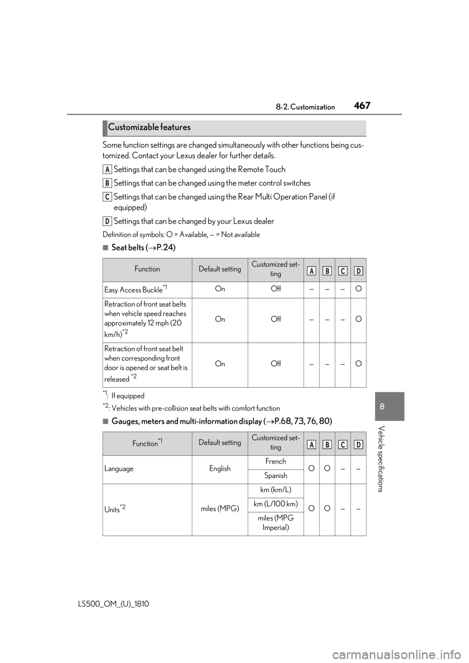
Vehicle specifications Some function settings are changed simultaneously with other functions being cus-
tomized. Contact your Lexus dealer for further details.
Settings that can be changed using the Remote Touch
Settings that can be changed using the meter control switches
Settings that can be changed using the Rear Multi Operation Panel (if
equipped)
Settings that can be changed by your Lexus dealerDefinition of symbols: O = Available, — = Not available ■
Seat belts ( P.24)
*1
: If equipped *2
: Vehicles with pre-collision se at belts with comfort function
■
Gauges, meters and multi-information display ( P.68, 73, 76, 80)Customizable features
Function Default setting Customized set-
ting
Easy Access Buckle *1
On Off — — — O
Retraction of front seat belts
when vehicle speed reaches
approximately 12 mph (20
km/h) *2
On Off — — — O
Retraction of front seat belt
when corresponding front
door is opened or seat belt is
released *2
On Off — — — O
Function *1
Default setting Customized set-
ting
Language English French
O O — —
Spanish
Units *2
miles (MPG) km (km/L)
O O — —km (L/100 km)
miles (MPG
Imperial)A
B
C
D
A B C D
A B C D
Page 468 of 512
468 8-2. Customization
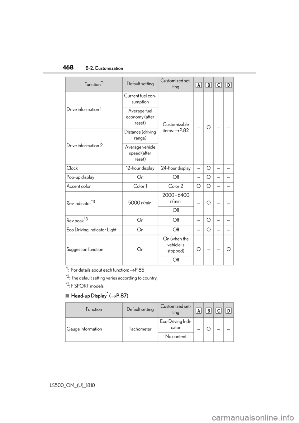
LS500_OM_(U)_1810 *1
: For details about each function: P.85*2
: The default setting varies according to country. *3
:F SPORT models
■
Head-up Display *
( P.87)Drive information 1 Current fuel con-
sumption
Customizable
items: P.82 — O — —Average fuel
economy (after
reset)
Drive information 2 Distance (driving
range)
Average vehicle
speed (after
reset)
Clock 12-hour display 24-hour display — O — —
Pop-up display On Off — O — —
Accent color Color 1 Color 2 O O — —
Rev indicator *3
5000 r/min. 2000 - 6400
r/min.
— O — —
Off
Rev peak *3
On Off — O — —
Eco Driving Indicator Light On Off — O — —
Suggestion function On On (when the
vehicle is
stopped) O — — O
Off
Function Default setting Customized set-
ting
Gauge information Tachometer Eco Driving Indi-
cator
— O — —
No contentFunction *1
Default setting Customized set-
ting A B C D
A B C D
Page 469 of 512
4698-2. Customization
LS500_OM_(U)_1810 8
Vehicle specifications *
:If equipped ■
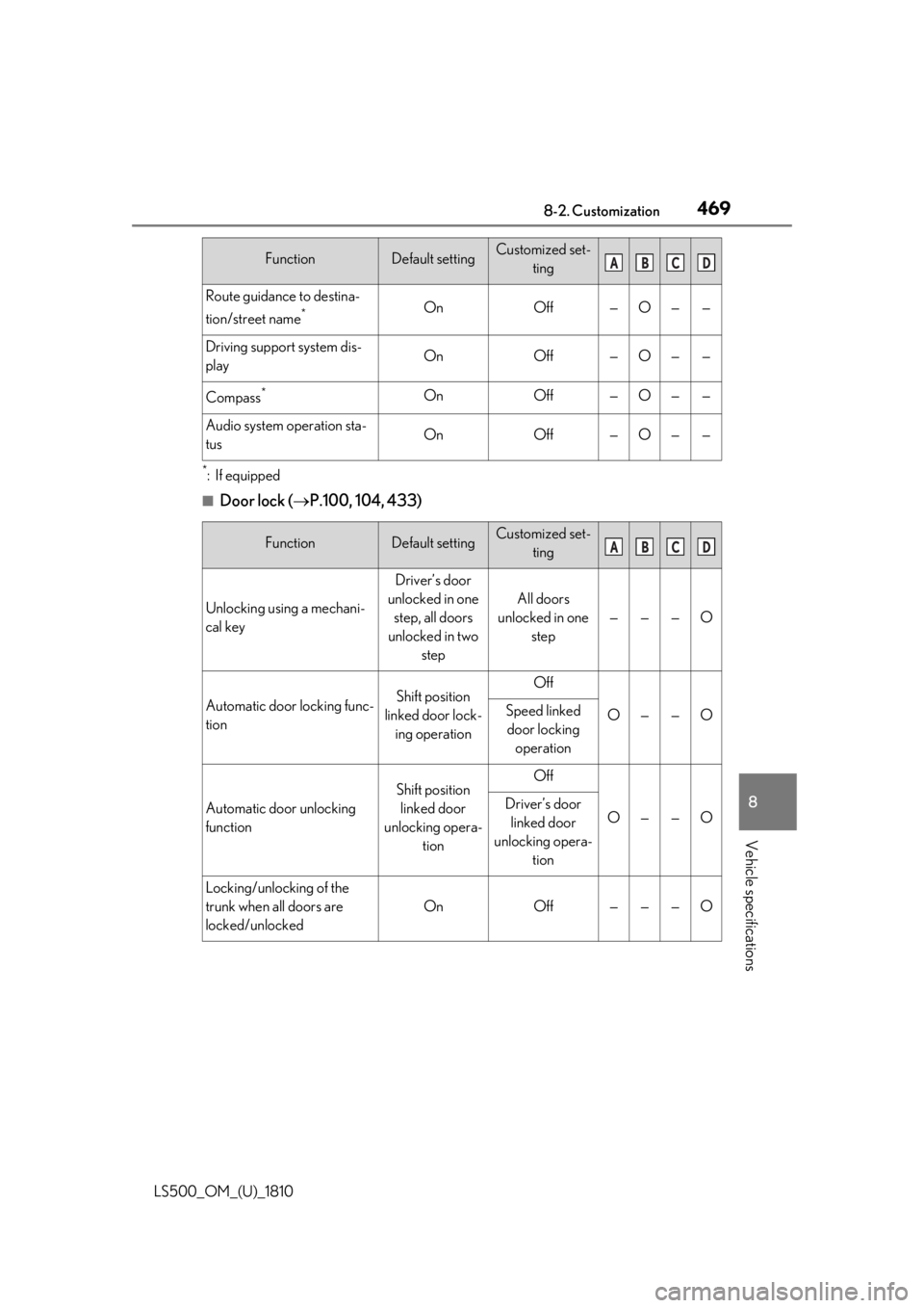
Door lock ( P.100, 104, 433)Route guidance to destina-
tion/street name *
On Off — O — —
Driving support system dis-
play On Off — O — —
Compass *
On Off — O — —
Audio system operation sta-
tus On Off — O — —
Function Default setting Customized set-
ting
Unlocking using a mechani-
cal key Driver’s door
unlocked in one
step, all doors
unlocked in two
step All doors
unlocked in one
step — — — O
Automatic door locking func-
tion Shift position
linked door lock-
ing operation Off
O — — OSpeed linked
door locking
operation
Automatic door unlocking
function Shift position
linked door
unlocking opera-
tion Off
O — — ODriver’s door
linked door
unlocking opera-
tion
Locking/unlocking of the
trunk when all doors are
locked/unlocked On Off — — — OFunction Default setting Customized set-
ting A B C D
A B C D
Page 470 of 512
470 8-2. Customization
LS500_OM_(U)_1810 ■
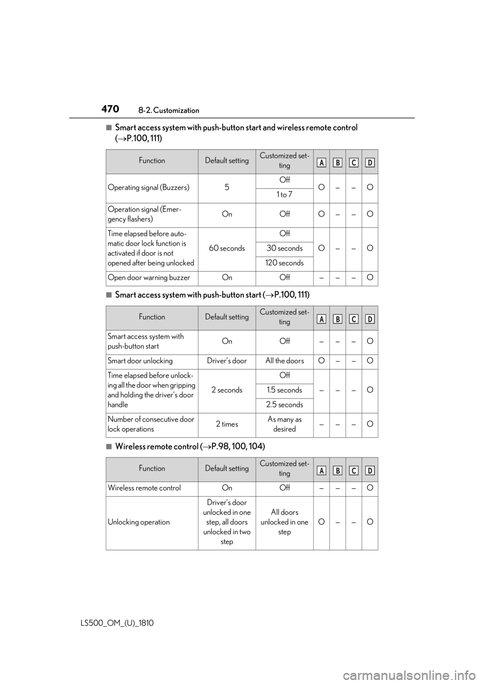
Smart access system with push-butto n start and wireless remote control
( P.100, 111)
■
Smart access system with push-button start ( P.100, 111)
■
Wireless remote control ( P.98, 100, 104)Function Default setting Customized set-
ting
Operating signal (Buzzers) 5 Off
O — — O
1 to 7
Operation signal (Emer-
gency flashers) On Off O — — O
Time elapsed before auto-
matic door lock function is
activated if door is not
opened after being unlocked 60 seconds Off
O — — O30 seconds
120 seconds
Open door warning buzzer On Off — — — O
Function Default setting Customized set-
ting
Smart access system with
push-button start On Off — — — O
Smart door unlocking Driver’s door All the doors O — — O
Time elapsed before unlock-
ing all the door when gripping
and holding the driver’s door
handle 2 seconds Off
— — — O1.5 seconds
2.5 seconds
Number of consecutive door
lock operations 2 times As many as
desired — — — O
Function Default setting Customized set-
ting
Wireless remote control On Off — — — O
Unlocking operation Driver’s door
unlocked in one
step, all doors
unlocked in two
step All doors
unlocked in one
step O — — O A B C D
A B C D
A B C D