ECU LEXUS LX570 2015 Manual PDF
[x] Cancel search | Manufacturer: LEXUS, Model Year: 2015, Model line: LX570, Model: LEXUS LX570 2015Pages: 960, PDF Size: 11.33 MB
Page 823 of 960

5
When trouble arises
8215-1. Essential information
LX570_OM_OM60L96U_(U) Emergency towing procedure
Securely attach a cable or chain to the towing hook.
Take care not to damage the vehicle body.
Enter the vehicle being towed and start the engine.
If the engine does not start, turn the “ENGINE START STOP”
switch to IGNITION ON mode.
Shift the four-wheel drive control switch to “H4”. (The center dif-
ferential is unlocked.)
Change the vehicle height to N (standard) mode and press the
height control OFF button to en d the vehicle height operation.
( P. 320)
Shift the shift lever to N and release the parking brake.
When the shift lever cannot be shifted: P. 870■
While towing
If the engine is not running, the power assist for the brakes and steering will not
function, making steering and braking more difficult. ■
Wheel nut wrench
Wheel nut wrench is installed in the luggage compartment. ( P. 854)STEP 1
STEP 2
STEP 3
STEP 4
STEP 5
Page 824 of 960

8225-1. Essential information
LX570_OM_OM60L96U_(U) CAUTIONObserve the following precautions.
Failure to do so may result in death or serious injury. ■
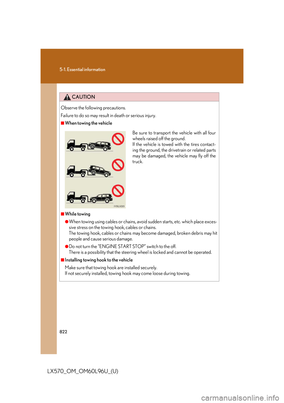
When towing the vehicle
■
While towing ●
When towing using cables or chains, avoi d sudden starts, etc. which place exces-
sive stress on the towing hook, cables or chains.
The towing hook, cables or chains may become damaged, broken debris may hit
people and cause serious damage. ●
Do not turn the “ENGINE START STOP” switch to the off.
There is a possibility that the steering wheel is locked and cannot be operated.■
Installing towing hook to the vehicle
Make sure that towing h ook are installed securely.
If not securely installed, towing hook may come loose during towing. Be sure to transport the vehicle with all four
wheels raised off the ground.
If the vehicle is towed with the tires contact-
ing the ground, the drivet rain or related parts
may be damaged, the vehicle may fly off the
truck.
Page 834 of 960

8325-2. Steps to take in an emergency
LX570_OM_OM60L96U_(U) ■
If the malfunction indicator lamp comes on while driving
First check the following: ●
Is the fuel empty?
If it is, fill the fuel tank immediately. ●
Is the fuel tank cap loose?
If it is, tighten it securely.
The malfunction indicator lamp will go off after taking several driving trips.
If the malfunction indicator lamp does not go off even after several trips, contact
your Lexus dealer as soon as possible. ■
If the low speed four-wheel drive indicato r light or the center differential lock
indicator light blinks
Take the specified steps. ( P. 335)
If the brake system warning light or the malfunction indicator light also comes on, or
the low speed four-wheel drive indicator light or the center differential lock indica-
tor light continues to blink after taking th e specified steps, there may be a malfunc-
tion in the engine, the brake system or the four-wheel drive system. In this case, you
may not be able to transfer between “H4” and “L4” modes, and the center differen-
tial lock may not be able to be locked or unlocked. Have the vehicle inspected by
your Lexus dealer, immediately. ■
Front passenger detection sensor and passenger seat belt reminder●
If luggage is placed on the front pass enger seat, the front passenger detection
sensor may cause the warning light to flash, even if a passenger is not sitting in
the seat. ●
If a cushion is placed on the seat, the sensor may not detect a passenger, and
the warning light may not operate properly.
Page 853 of 960

5
When trouble arises
8515-2. Steps to take in an emergency
LX570_OM_OM60L96U_(U) Once
(Flashes) •When the doors
were unlocked
with the
mechanical key
and then the
“ENGINE
START STOP”
switch was
pressed, the
electronic key
could not be
detected in the
vehicle.
• The electronic
key could not be
detected in the
vehicle even
after the
“ENGINE
START STOP”
switch was
pressed two
consecutive
times. Touch the elec-
tronic key to the
“ENGINE START
STOP” switch
while depressing
the brake pedal.Interior
buzzer Exterior
buzzerWarning message Details Correction
procedure
Page 867 of 960

5
When trouble arises
8655-2. Steps to take in an emergency
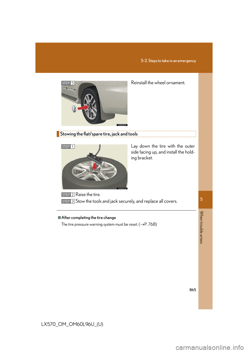
LX570_OM_OM60L96U_(U) Reinstall the wheel ornament.
Stowing the flat/spare tire, jack and tools
Lay down the tire with the outer
side facing up, and install the hold-
ing bracket.
Raise the tire.
Stow the tools and jack secu rely, and replace all covers.STEP 5
STEP 1
■
After completing the tire change
The tire pressure warning system must be reset. ( P. 768)STEP 2
STEP 3
Page 868 of 960

8665-2. Steps to take in an emergency
LX570_OM_OM60L96U_(U) CAUTION■
Using the tire jack
Improper use of the tire jack may lead to death or serious injuries due to the vehicle
suddenly falling off the jack. ●
Do not use the tire jack for any purpose other than replacing tires or installing
and removing tire chains. ●
Only use the tire jack that comes with this vehicle for replacing a flat tire.
Do not use it on other vehicles, and do no t use other tire jack s for replacing tires
on this vehicle. ●
Always check that the tire jack is securely set to the jack point. ●
Be sure to turn off the 4-Wheel AHC and stop the engine. ●
Do not put any part of your body un der the vehicle supported by a jack.●
Do not start or run the engine while your vehicle is supported by the jack. ●
Do not raise the vehicle while someone is in it. ●
When raising the vehicle, do not put an object on or under the jack. ●
Do not raise the vehicle to a height greate r than that required to replace the tire.●
Use a jack stand if it is necessary to get under the vehicle.
Take particular care when lowering the vehi cle to ensure that no one working on or
near the vehicle will be injured. ■
Using the jack handle
Tighten all the jack handle bolts securely using a Phillips-head screwdriver, to pre-
vent the extension parts from coming apart unexpectedly.
Page 886 of 960

8845-2. Steps to take in an emergency
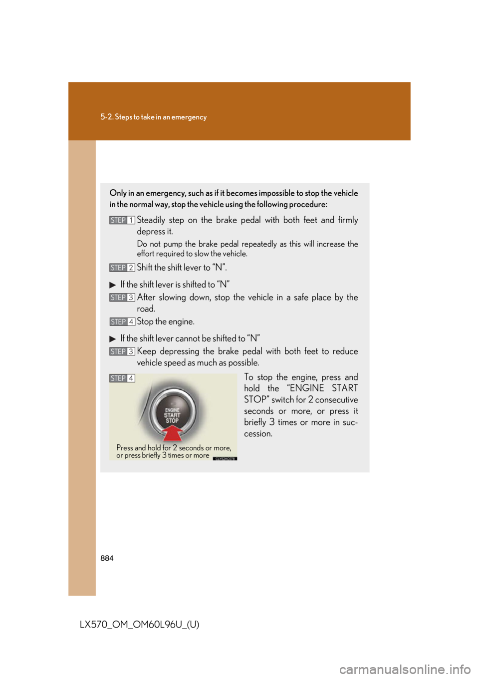
LX570_OM_OM60L96U_(U) If your vehicle has to be stopped in an emergency Only in an emergency, such as if it becomes impossible to stop the vehicle
in the normal way, stop the vehi cle using the following procedure:
Steadily step on the brake pedal with both feet and firmly
depress it. Do not pump the brake pedal repeatedly as this will increase the
effort required to slow the vehicle.
Shift the shift lever to “N”.
If the shift lever is shifted to “N”
After slowing down, stop the ve hicle in a safe place by the
road.
Stop the engine.
If the shift lever cannot be shifted to “N”
Keep depressing the brake peda l with both feet to reduce
vehicle speed as much as possible.
To stop the en gine, press and
hold the “ENGINE START
STOP” switch for 2 consecutive
seconds or more, or press it
briefly 3 times or more in suc-
cession.STEP 1
STEP 2
STEP 3
STEP 4
STEP 3
STEP 4
Press and hold for 2 seconds or more,
or press briefly 3 times or more
Page 915 of 960

9116-1. Specifications
6
Vehicle specifications
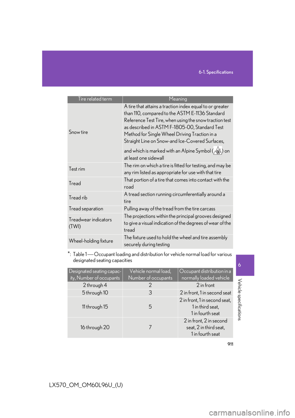
LX570_OM_OM60L96U_(U) * :Table 1 Occupant loading and distribution for vehicle normal load for various
designated seating capacities Tire related term Meaning
Snow tire A tire that attains a tractio n index equal to or greater
than 110, compared to th e ASTM E-1136 Standard
Reference Test Tire, when using the snow traction test
as described in ASTM F-1805-00, Standard Test
Method for Single Wheel Driving Traction in a
Straight Line on Snow-and Ice-Covered Surfaces,
and which is marked with an Alpine Symbol ( ) on
at least one sidewall
Test rim The rim on which a tire is fitted for testing, and may be
any rim listed as appropriate for use with that tire
Tread That portion of a tire that comes into contact with the
road
Tread rib A tread section running circumferentially around a
tire
Tread separation Pulling away of the tread from the tire carcass
Treadwear indicators
(TWI) The projections within the principal grooves designed
to give a visual indication of the degrees of wear of the
tread
Wheel-holding fixture The fixture used to hold the wheel and tire assembly
securely during testing
Designated seating capac-
ity, Number of occupants Vehicle normal load,
Number of occupants Occupant distribution in a
normally loaded vehicle
2 through 4 2 2 in front
5 through 10 3 2 in front, 1 in second seat
11 through 15 5 2 in front, 1 in second seat,
1 in third seat,
1 in fourth seat
16 through 20 7 2 in front, 2 in second
seat, 2 in third seat,
1 in fourth seat