ESP LEXUS RX200T 2017 Owners Manual
[x] Cancel search | Manufacturer: LEXUS, Model Year: 2017, Model line: RX200T, Model: LEXUS RX200T 2017Pages: 776, PDF Size: 44.51 MB
Page 33 of 776
331-1. For safe use
1
For safety and security
RX350/RX200t_EE_OM48F32E
WARNING
Observe the following precautions. Failure to do so may cause the driver’s floor mat to slip, possibly interfering with the ped-als while driving. An unexpect edly high speed may result or it may become difficult to
stop the vehicle. This could lead to an acci dent, resulting in death or serious injury.
■When installing the driver’s floor mat
●Do not use floor mats designed for other models or different model year vehicles,
even if they are Lexus Genuine floor mats.
●Only use floor mats designed for the driver’s seat.
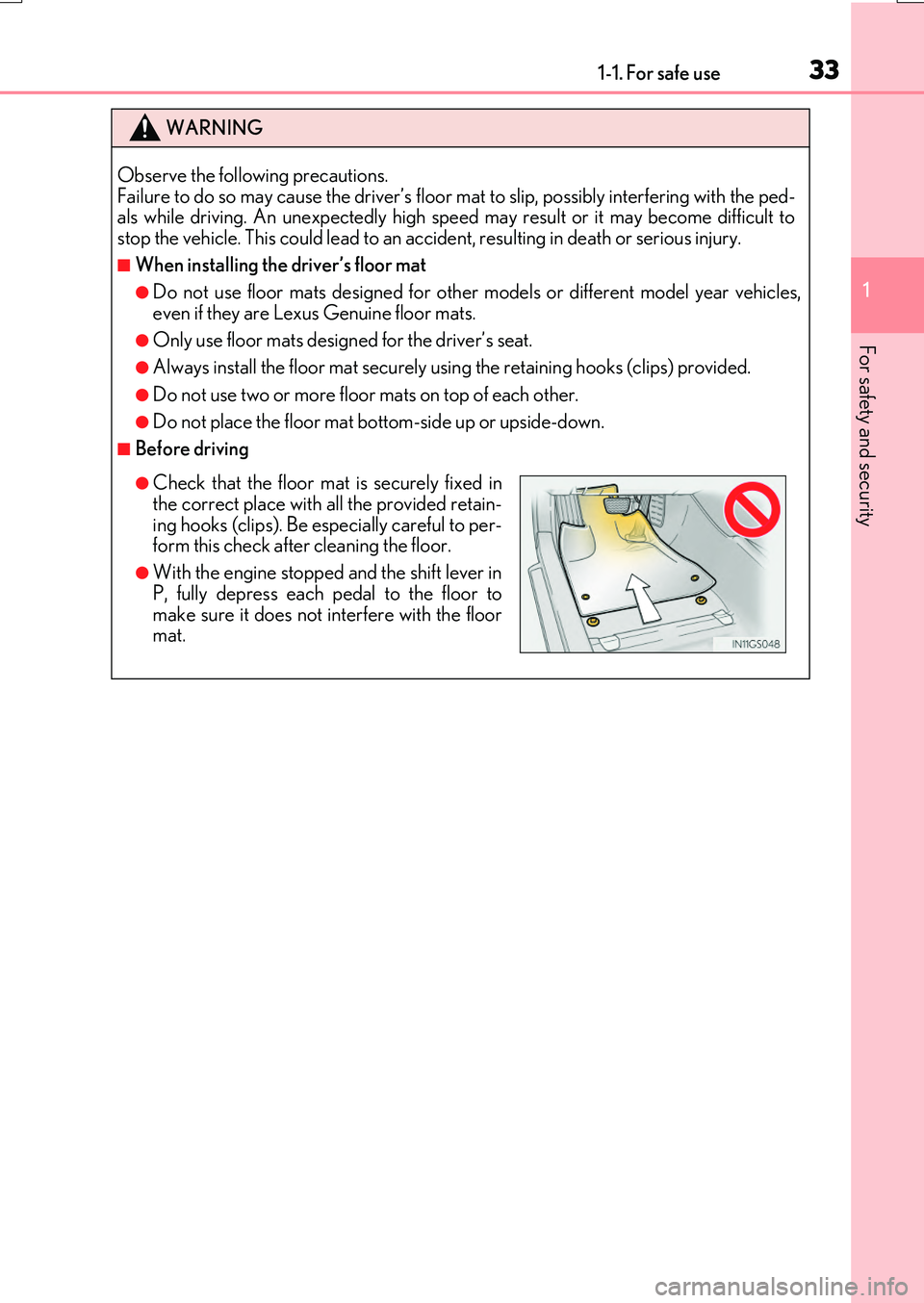
●Always install the floor mat securely us ing the retaining hooks (clips) provided.
●Do not use two or more floor mats on top of each other.
●Do not place the floor mat bottom-side up or upside-down.
■Before driving
●Check that the floor mat is securely fixed in the correct place with all the provided retain-
ing hooks (clips). Be especially careful to per- form this check after cleaning the floor.
●With the engine stopped and the shift lever in
P, fully depress each pedal to the floor to make sure it does not interfere with the floormat.
Page 43 of 776
431-1. For safe use
1
For safety and security
RX350/RX200t_EE_OM48F32E
WARNING
■SRS airbag precautions
Observe the following precaution s regarding the SRS airbags. Failure to do so may cause death or serious injury.
●The driver and all passengers in the vehicle must wear their seat belts properly.The SRS airbags are supplemental devices to be used with the seat belts.
●The SRS driver airbag deploys with considerable force, and can cause death or seri-
ous injury especially if the driv er is very close to the airbag.
Since the risk zone for the driver’s airbag is the first 50 - 75 mm (2 - 3 in.) of inflation, placing yourself 250 mm (10 in.) from your driver airbag provides you with a clear
margin of safety. This distance is measured from the center of the steering wheel to your breastbone. If you sit less than 250 mm (10 in.) away now, you can change yourdriving position in several ways:
• Move your seat to the rear as far as you can while still reaching the pedals com- fortably.• Slightly recline the back of the seat.
Although vehicle designs vary, many drivers can achieve the 250 mm (10 in.) dis- tance, even with the driver seat all the way forward, simply by reclining the back ofthe seat somewhat. If reclining the back of your seat makes it hard to see the road,
raise yourself by using a firm, non-slippery cushion, or raise the seat if your vehicle has that feature.• If your steering wheel is adjustable, tilt it downward. This points the airbag toward
your chest instead of your head and neck. The seat should be adjusted as recommend ed above, while still maintaining control of the foot pedals, steering wheel, and your view of the instrument panel controls.
●The SRS front passenger airbag also deploys with considerable force, and can causedeath or serious injury especially if the fron t passenger is very close to the airbag. The front passenger seat should be as far from the airbag as possible with the seatback
adjusted, so the front passenger sits upright.
●Improperly seated and/or restrained infant s and children can be killed or seriously injured by a deploying airbag. An infant or child who is too small to use a seat belt
should be properly secured using a child restraint system. Lexus strongly recom- mends that all infants and children be placed in the rear seats of the vehicle and prop-erly restrained. The rear seats are safer for infants and children than the front
passenger seat. ( P. 54)
Page 47 of 776
471-1. For safe use
1
For safety and security
RX350/RX200t_EE_OM48F32E
■SRS airbag deployment conditions (SRS front airbags)
●The SRS front airbags will deploy in the event of an impact that exceeds the set thresh- old level (the level of force correspon ding to an approximately 20 - 30 km/h
[12 - 18 mph] frontal collision with a fixed wall that does not move or deform).
However, this threshold velocity will be cons iderably higher in the following situations:
• If the vehicle strikes an object, such as a parked vehicle or sign pole, which can move
or deform on impact • If the vehicle is involved in an underride collision, such as a collision in which the front of the vehicle “underrides”, or goes under, the bed of a truck
●Depending on the type of collision, it is possib le that only the seat belt pretensioners will activate.
●The SRS seat cushion airbag on the front pa ssenger seat will not operate if the occu- pant is not wearing a seat belt.
■SRS airbag deployment conditions (SRS side and curtain shield airbags)
●The SRS side and curtain shield airbags w ill deploy in the event of an impact that exceeds the set threshold level (the level of force corresponding to the impact forceproduced by an approximately 1500 kg [3300 lb.] vehicle colliding with the vehicle
cabin from a direction perpendicular to the vehicle orientation at an approximate speed of 20 - 30 km/h [12 - 18 mph]).
●The SRS side and curtain shield airbags will de ploy in the event of a severe frontal colli-
sion.
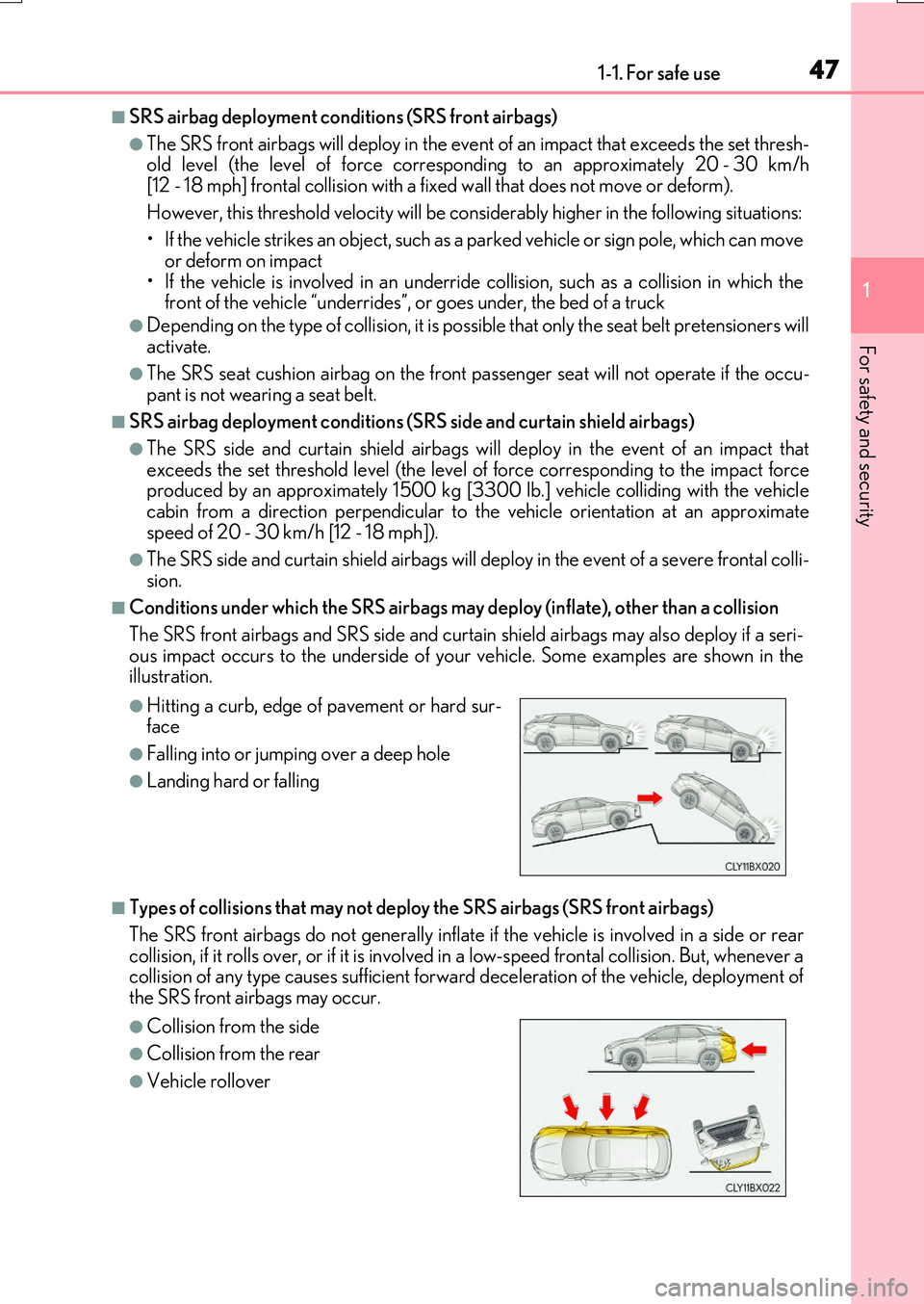
■Conditions under which the SRS airbags may deploy (inflate), other than a collision
The SRS front airbags and SRS side and curtain shield airbags may also deploy if a seri-
ous impact occurs to the underside of your vehicle. Some examples are shown in the illustration.
■Types of collisions that may not depl oy the SRS airbags (SRS front airbags)
The SRS front airbags do not generally inflate if the vehicle is involved in a side or rear
collision, if it rolls over, or if it is involved in a low-speed frontal collision. But, whenever a collision of any type causes sufficient forward deceleration of the vehicle, deployment of the SRS front airbags may occur.
●Hitting a curb, edge of pavement or hard sur-face
●Falling into or jumpin g over a deep hole
●Landing hard or falling
●Collision from the side
●Collision from the rear
●Vehicle rollover
Page 62 of 776
621-2. Child safety
RX350/RX200t_EE_OM48F32E
◆Confirming the possible installation seating positions and the Mass Group
for the seat belt installation type child restraint systems.
Confirm the corresponding [Mass group] from the weight of the child
( P. 57)
(Ex. 1) When the weight is 12 kg (27 lb.), [Mass group 0+]
(Ex. 2) When the weight is 15 kg (34 lb.), [Mass group I]
Confirm and select the appropriate possible seating position for the child
restraint system and the corresponding type of system from the [Child
restraint system suitability table]. ( P. 63)
Child restraint system fixed with a seat belt
1
2
Page 69 of 776
691-2. Child safety
1
For safety and security
RX350/RX200t_EE_OM48F32E
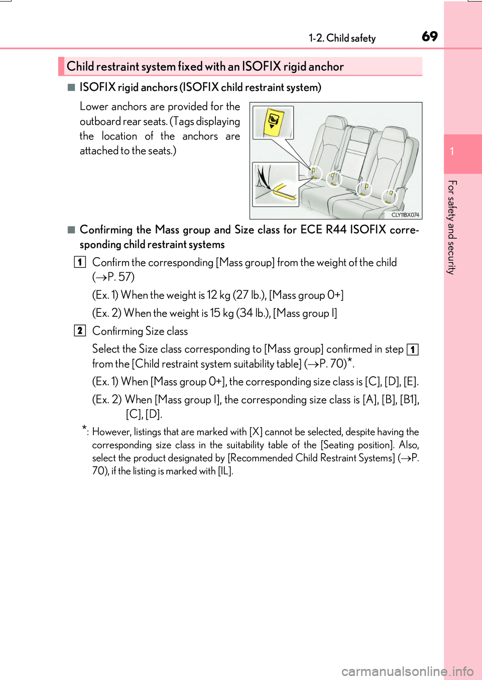
■ISOFIX rigid anchors (ISOFIX child restraint system)
Lower anchors are provided for the
outboard rear seats. (Tags displaying
the location of the anchors are
attached to the seats.)
■Confirming the Mass group and Size class for ECE R44 ISOFIX corre-
sponding child restraint systems
Confirm the corresponding [Mass group] from the weight of the child
( P. 57)
(Ex. 1) When the weight is 12 kg (27 lb.), [Mass group 0+]
(Ex. 2) When the weight is 15 kg (34 lb.), [Mass group I]
Confirming Size class
Select the Size class corresponding to [Mass group] confirmed in step
from the [Child restraint system suitability table] ( P. 70)*.
(Ex. 1) When [Mass group 0+], the corresponding size class is [C], [D], [E].
(Ex. 2) When [Mass group I], the corresponding size class is [A], [B], [B1],
[C], [D].
*: However, listings that are marked with [X] cannot be selected, despite having the
corresponding size class in the suitability table of the [Seating position]. Also,
select the product designated by [Rec ommended Child Restraint Systems] (P.
70), if the listing is marked with [IL].
Child restraint system fixed with an ISOFIX rigid anchor
1
2
1
Page 85 of 776

851-3. Theft deterrent system
1
For safety and security
RX350/RX200t_EE_OM48F32E
●The intrusion sensor detects intruders or movement in the vehicle.
●The tilt sensor detects changes in vehicle inclination, such as when the vehicle
is towed away.
This system is designed to deter and pr event vehicle theft but does not guarantee
absolute security against all intrusions.
■Setting the intrusion sensor and tilt sensor
The intrusion sensor and tilt sensor will be set automatically when the alarm is
set. ( P. 83)
■Canceling the intrusion sensor and tilt sensor
If you are leaving pets or other moving things inside the vehicle, make sure to
disable the intrusion sensor and tilt sensor before setting the alarm, as they will
respond to movement inside the vehicle.
Turn the engine switch off.
Press the intrusion sensor and tilt
sensor cancel switch.
A message will be shown on the
multi-information display in the
instrument cluster.
The intrusion sensor and tilt sen-
sor will revert to on each time the
engine switch is turned to IGNI-
TION ON mode.
NOTICE
■To ensure the system operates correctly
Do not modify or remove the system. If modi fied or removed, the proper operation of the system cannot be guaranteed.
Intrusion sensor (if equipped) /Intrusion sensor and tilt sensor
(if equipped)
1
2
Page 116 of 776
1162. Instrument cluster
RX350/RX200t_EE_OM48F32E
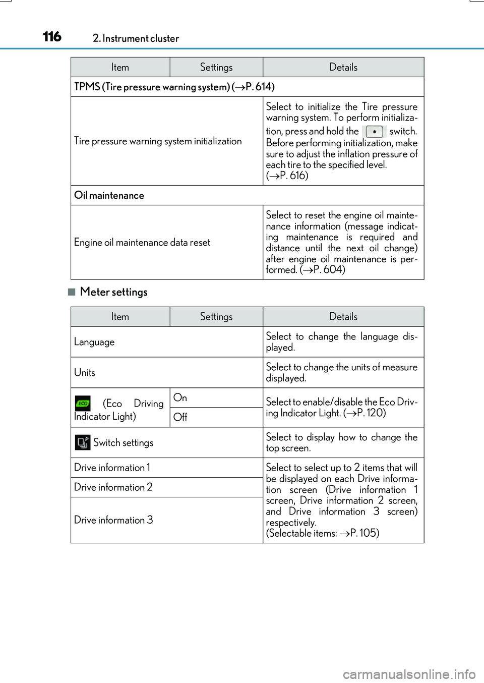
■Meter settings
TPMS (Tire pressure warning system) (P. 614)
Tire pressure warning system initialization
Select to initialize the Tire pressure warning system. To perform initializa-
tion, press and hold the switch.
Before performing initialization, make
sure to adjust the inflation pressure of each tire to the specified level. ( P. 616)
Oil maintenance
Engine oil maintenance data reset
Select to reset the engine oil mainte-
nance information (message indicat- ing maintenance is required anddistance until the next oil change)
after engine oil maintenance is per- formed. ( P. 604)
ItemSettingsDetails
ItemSettingsDetails
Language Select to change the language dis-
played.
UnitsSelect to change the units of measure displayed.
(Eco Driving
Indicator Light)
OnSelect to enable/disable the Eco Driv-
ing Indicator Light. ( P. 120)Off
Switch settingsSelect to display how to change the top screen.
Drive information 1Select to select up to 2 items that will
be displayed on each Drive informa- tion screen (Drive information 1screen, Drive information 2 screen,
and Drive information 3 screen) respectively. (Selectable items: P. 105)
Drive information 2
Drive information 3
Page 119 of 776
1192. Instrument cluster
2
Instrument cluster
RX350/RX200t_EE_OM48F32E
Displays suggestions to the driver in the following situations. To select a response
to a displayed suggestion, use the meter control switches.
The suggestion function can be turned on/off. (Customizable features: P. 740)
■Suggestion to enable the po wer back door (if equipped)
If the power back door system is disabled (setting on set to off) and the
power back door switch on the instrument panel is operated, a suggestion
message will be displayed asking if you wish to enable the power back door
system. To enable the power back door system, select “Yes”.
After enabling the power back door system, press the power back door switch
again to open or close the power back door.
■Suggestion to close the power windows (linked to windshield wiper opera-
tion)
If the windshield wipers are operated with a power window open, a suggestion
message will be displayed asking if you wish to close the power windows. To
close all of the power windows, select “Yes”.
■Suggestion to close the po wer windows (linked to engine switch operation)
If the engine switch is turned off with a power window open, a suggestion
message will be displayed asking if you wish to close the power windows. To
close all of the power windows, select “Yes”.
Suggestion function
Page 121 of 776
1212. Instrument cluster
2
Instrument cluster
RX350/RX200t_EE_OM48F32E
■Tire pressure
●It may take a few minutes to display the tire inflation pressure after the engine switch is turned to IGNITION ON mode. It may also take a few minutes to display the tire infla-
tion pressure after inflation pressure has been adjusted.
●“---” may be displayed if the tire position information cannot be determined due to unfavorable radio wave conditions.
●Tire inflation pressure changes with temperature. The displayed values may also be dif-ferent from the values measured using a tire pressure gauge.
■Liquid crystal display
Small spots or light spots may appear on th e display. This phenomenon is characteristic of liquid crystal displays, and there is no problem continuing to use the display.
■Customization
Some functions can be customized. ( P. 110, 740)
WARNING
■Caution for use while driving
●When operating the multi-information display while driving, pay extra attention to the safety of the area around the vehicle.
●Do not look continuously at the multi-info rmation display while driving as you may fail to see pedestrians, objects on the road, etc. ahead of the vehicle.
■The information display at low temperatures
Allow the interior of the vehicle to warm up before using the liquid crystal information display. At extremely low temperatures, th e information display monitor may respond slowly, and display changes may be delayed.
For example, there is a lag between the dr iver’s shifting and the new gear number appearing on the display. This lag could cau se the driver to downshift again, causing rapid and excessive engine braking and po ssibly an accident resulting in death or
injury.
■Cautions during setting up the display
As the engine needs to be running during setting up the display, ensure that the vehicle
is parked in a place with adequate ventilation. In a closed area such as a garage, exhaust gases including harmful carbon monoxide (CO) may collect and enter thevehicle. This may lead to death or a serious health hazard.
NOTICE
■While setting up the display
To prevent battery discharge, ensure that the engine is running while setting up the dis- play features.
Page 126 of 776
1262. Instrument cluster
RX350/RX200t_EE_OM48F32E
■Head-up display
The head-up display may seem dark or hard to see when viewed through sunglasses,
especially polarized sunglasses.
Adjust the brightness of the head-u p display or remove your sunglasses.
■When the battery is disconnected
The customize settings of the head-up display will be reset.
■Display brightness
The brightness of the head-up display can be adjusted on of the multi-information
display. Also, it is automatically adjust ed according to the ambient brightness.
■Enabling/disabling of the head-up display
If the head-up display is disabled, it will rema in disabled when the engine switch is turned
off then back to IGNITION ON mode.
■Street name display (vehicles with a navigation system)
Only street names which are included in the map data will be displayed.
WARNING
■Before using the head-up display
●Check that the position and brightness of the head-up display image does not inter-
fere with safe driving. Incorrect adjustment of the image’s position or brightness may
obstruct the driver’s view and lead to an accident, resulting in death or serious injury.
●Do not continuously look at the head-up display while driving as you may fail to see
pedestrians, objects on the road, etc. ahead of the vehicle.
■Caution for changing settings of the head-up display
As the engine needs to be running while changing the settings of the head-up display,
ensure that the vehicle is parked in a place with adequate ventilation. In a closed area
such as a garage, exhaust gases including harmful carbon monoxide (CO) may collect
and enter the vehicle. This may lead to death or a serious health hazard.