navigation LEXUS RX350 2020 User Guide
[x] Cancel search | Manufacturer: LEXUS, Model Year: 2020, Model line: RX350, Model: LEXUS RX350 2020Pages: 516, PDF Size: 17.3 MB
Page 112 of 516
1123-2. Opening, closing and locking the doors
The Hands Free Power Back Door
(kick sensor) can be enabled/disabled
on the multi-information display.
( P.79)
1 Press or of the meter con-
trol switches and select .
2 Press or of the meter con-
trol switches, select the “Vehicle
Settings” and then press .
3 Press or of the meter con-
trol switches, select and
then press .
4 Press or of the meter con-
trol switches, and then select “Kick
Sensor”.
5 ON and OFF will be switched over
with presses of on the meter
control switches.
When OFF is selected and the operations
of the Hands Free Power Back Door is
made to stop from the of multi-infor-
mation display, unless it is set to ON, the
operation of the Hands Free Power Back
Door will not return. (No return in the
engine switch operation)
The open position of the power back-
door can be adjusted.
1 Stop the power back door at the
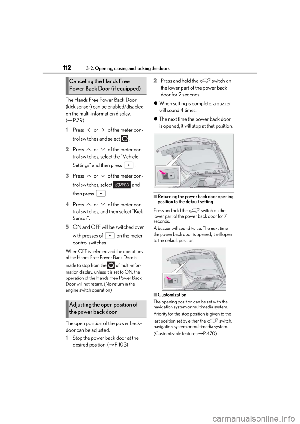
desired position. ( P.103) 2
Press and hold the switch on
the lower part of the power back
door for 2 seconds.
When setting is complete, a buzzer
will sound 4 times.
The next time the power back door
is opened, it will stop at that position.
■Returning the power back door opening
position to the default setting
Press and hold the switch on the
lower part of the power back door for 7
seconds.
A buzzer will sound twice. The next time
the power back door is opened, it will open
to the default position.
■Customization
The opening position can be set with the
navigation system or multimedia system.
Priority for the stop position is given to the
last position set by either the switch,
navigation system or multimedia system.
(Customizable features: P.470)
Canceling the Hands Free
Power Back Door (if equipped)
Adjusting the open position of
the power back door
Page 227 of 516
2274-5. Using the driving support systems
4
Driving
■Customization
Function settings can be changed. (Cus-
tomizable features: P.470)
*: If equipped
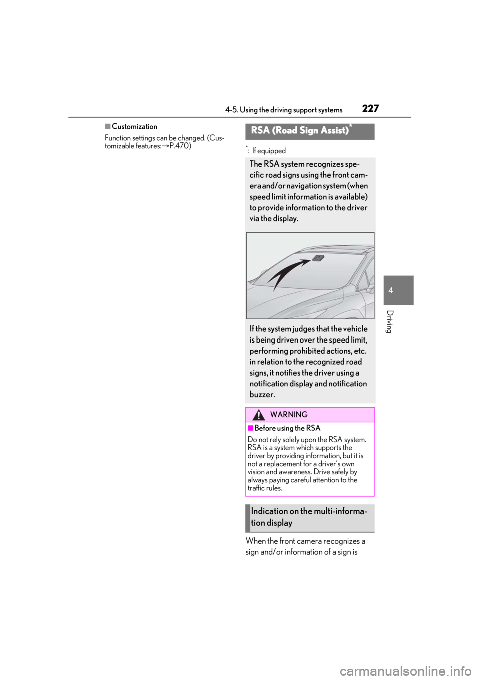
When the front camera recognizes a
sign and/or information of a sign is
RSA (Road Sign Assist)*
The RSA system recognizes spe-
cific road signs using the front cam-
era and/or navigation system (when
speed limit information is available)
to provide information to the driver
via the display.
If the system judges that the vehicle
is being driven over the speed limit,
performing prohibited actions, etc.
in relation to the recognized road
signs, it notifies the driver using a
notification display and notification
buzzer.
WARNING
■Before using the RSA
Do not rely solely upon the RSA system.
RSA is a system which supports the
driver by providing information, but it is
not a replacement for a driver’s own
vision and awareness. Drive safely by
always paying careful attention to the
traffic rules.
Indication on the multi-informa-
tion display
Page 228 of 516
2284-5. Using the driving support systems
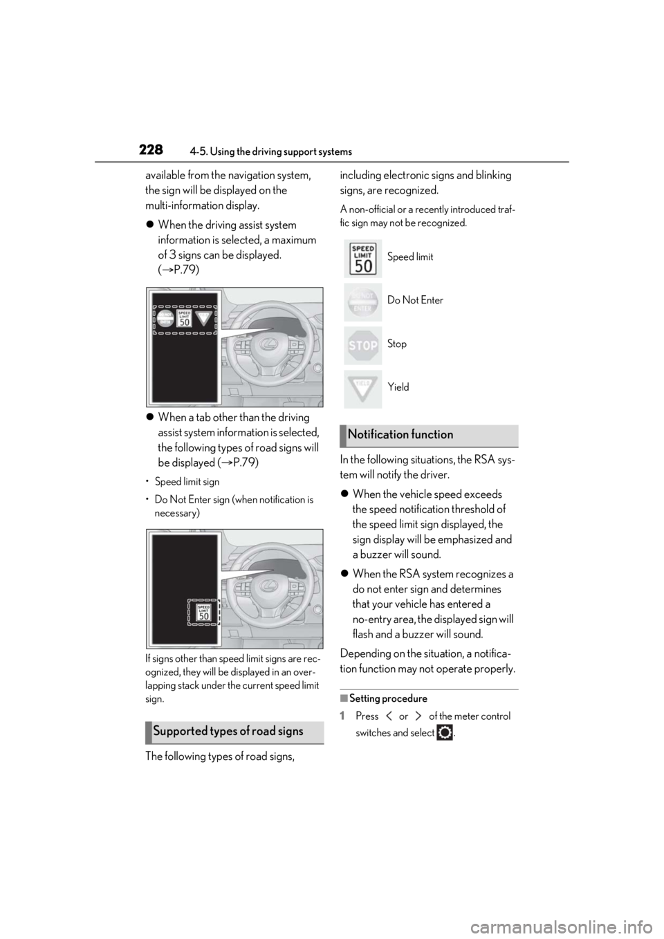
available from the navigation system,
the sign will be displayed on the
multi-information display.
When the driving assist system
information is selected, a maximum
of 3 signs can be displayed.
( P.79)
When a tab other than the driving
assist system information is selected,
the following types of road signs will
be displayed ( P.79)
• Speed limit sign
• Do Not Enter sign (when notification is
necessary)
If signs other than speed limit signs are rec-
ognized, they will be displayed in an over-
lapping stack under the current speed limit
sign.
The following types of road signs, including electronic signs and blinking
signs, are recognized.
A non-official or a recently introduced traf-
fic sign may not be recognized.
In the following situations, the RSA sys-
tem will notify the driver.
When the vehicle speed exceeds
the speed notification threshold of
the speed limit sign displayed, the
sign display will be emphasized and
a buzzer will sound.
When the RSA system recognizes a
do not enter sign and determines
that your vehicle has entered a
no-entry area, the displayed sign will
flash and a buzzer will sound.
Depending on the situation, a notifica-
tion function may not operate properly.
■Setting procedure
1 Press or of the meter control
switches and select .
Supported types of road signs
Speed limit
Do Not Enter
Stop
Yield
Notification function
Page 229 of 516
2294-5. Using the driving support systems
4
Driving
2Press or of the meter control
switches and select , then press
.
3 Press or of the meter control
switches and select “RSA”, then press
.
■Automatic turn-off of RSA sign display
In the following situations, a displayed
speed limit, do not enter signs will stop
being displayed automatically:
●A new sign is not recognized for a certain
distance.
●The road changes due to a left or right
turn, etc.
In the following situations, stop and yield
signs will stop being displayed automati-
cally:
●The system determines that your vehicle
has passed the sign.
●The road changes due to a left or right
turn, etc.
■Conditions in whic h the function may
not operate or detect correctly
In the following situations, RSA does not
operate normally and may not recognize
signs, display the incorrect sign, etc. How-
ever, this does not indicate a malfunction.
●The front camera is misaligned due to a
strong impact being applied to the sen-
sor, etc.
●Dirt, snow, stickers, etc. are on the wind-
shield near the front camera.
●In inclement weather such as heavy rain,
fog, snow or sand storms
●Light from an oncoming vehicle, the sun,
etc. enters the front camera.
●The sign is dirty, faded, tilted or bent.
●All or part of the sign is hidden by the
leaves of a tree, a pole, etc.
●The sign is only visible to the front camera
for a short amount of time.
●The driving scene (turning, lane change,
etc.) is judged incorrectly.
●Even if it is a sign not appropriate for the currently traveled lane, such a sign exists
directly after a freeway branches, or in an
adjacent lane just before merging.
●Stickers are attached to the rear of the
preceding vehicle.
●A sign resembling a system compatible
sign is recognized.
●Side road speed signs may be detected
and displayed (if positioned in sight of the
front camera) while the vehicle is travel-
ing on the main road.
●Roundabout exit road speed signs may
be detected and displayed (if positioned
in sight of the front camera) while travel-
ing on a roundabout.
●The front of the vehicle is raised or low-
ered due to the carried load
●The surrounding brightness is not suffi-
cient or changes suddenly.
●When a sign intended for trucks, etc. is
recognized.
●The speed information displayed on the
meter and that displayed on the naviga-
tion system may be different due to the
navigation system using map data.
■Speed limit sign display
If the engine switch wa s last turned off while
a speed limit sign was displayed on the
multi-information display, the same sign dis-
plays again when the engine switch is
turned to IGNITION ON mode.
■Customization
Some functions can be customized. (Cus-
tomizable features: P.470)
Page 290 of 516
2905-1. Remote Touch/Display
5-1.Remote Touch/Display
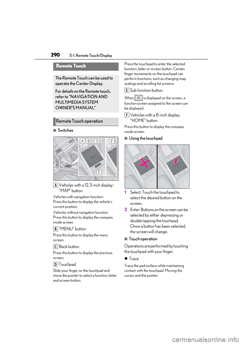
■SwitchesVehicles with a 12.3-inch display:
“MAP” button
Vehicles with navigation function:
Press this button to display the vehicle’s
current position.
Vehicles without navigation function:
Press this button to display the compass
mode screen.
“MENU” button
Press this button to display the menu
screen.
Back button
Press this button to display the previous
screen.
Touchpad
Slide your finger on the touchpad and
move the pointer to select a function, letter
and screen button. Press the touchpad to enter the selected
function, letter or screen button. Certain
finger movements on the touchpad can
perform functions, su
ch as changing map
scalings and scrolling list screens.
Sub function button
When is displayed on the screen, a
function screen assigned to the screen can
be displayed.
Vehicles with a 8-inch display:
“HOME” button
Press this button to display the compass
mode screen.
■Using the touchpad
1 Select: Touch the touchpad to
select the desired button on the
screen.
2 Enter: Buttons on the screen can be
selected by either depressing or
double tapping the touchpad.
Once a button has been selected,
the screen will change.
■Touch operation
Operations are performed by touching
the touchpad with your finger.
Trace
Trace the pad surface while maintaining
contact with the touchpad. Moving the
cursor and the pointer.
Remote Touch
The Remote Touch can be used to
operate the Center Display.
For details on the Remote touch,
refer to “NAVIGATION AND
MULTIMEDIA SYSTEM
OWNER’S MANUAL”.
Remote Touch operation
A
B
C
D
E
F
Page 292 of 516
2925-1. Remote Touch/Display
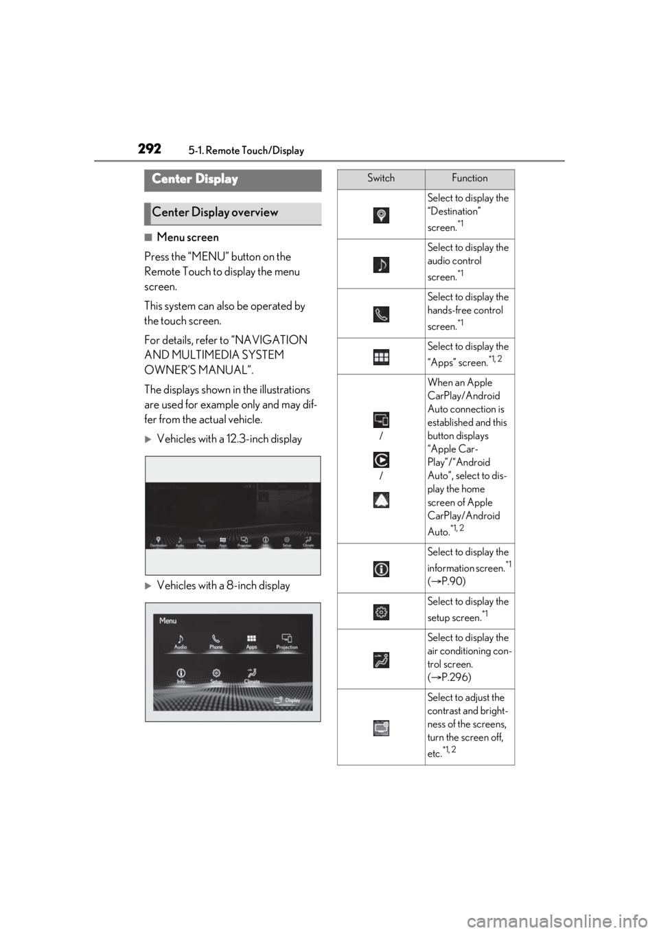
■Menu screen
Press the “MENU” button on the
Remote Touch to display the menu
screen.
This system can also be operated by
the touch screen.
For details, refer to “NAVIGATION
AND MULTIMEDIA SYSTEM
OWNER’S MANUAL”.
The displays shown in the illustrations
are used for example only and may dif-
fer from the actual vehicle.
Vehicles with a 12.3-inch display
Vehicles with a 8-inch display
Center Display
Center Display overview
SwitchFunction
Select to display the
“Destination”
screen.
*1
Select to display the
audio control
screen.
*1
Select to display the
hands-free control
screen.
*1
Select to display the
“Apps” screen.
*1, 2
/
/
When an Apple
CarPlay/Android
Auto connection is
established and this
button displays
“Apple Car-
Play”/“Android
Auto”, select to dis-
play the home
screen of Apple
CarPlay/Android
Auto.
*1, 2
Select to display the
information screen.
*1
( P.90)
Select to display the
setup screen.
*1
Select to display the
air conditioning con-
trol screen.
( P.296)
Select to adjust the
contrast and bright-
ness of the screens,
turn the screen off,
etc.
*1, 2
Page 293 of 516
2935-1. Remote Touch/Display
5
Interior features
*1: Refer to “NAVIGATION AND MULTI-MEDIA SYSTEM OWNER’S MAN-
UAL”.*2: This function is not made available in some models or areas.
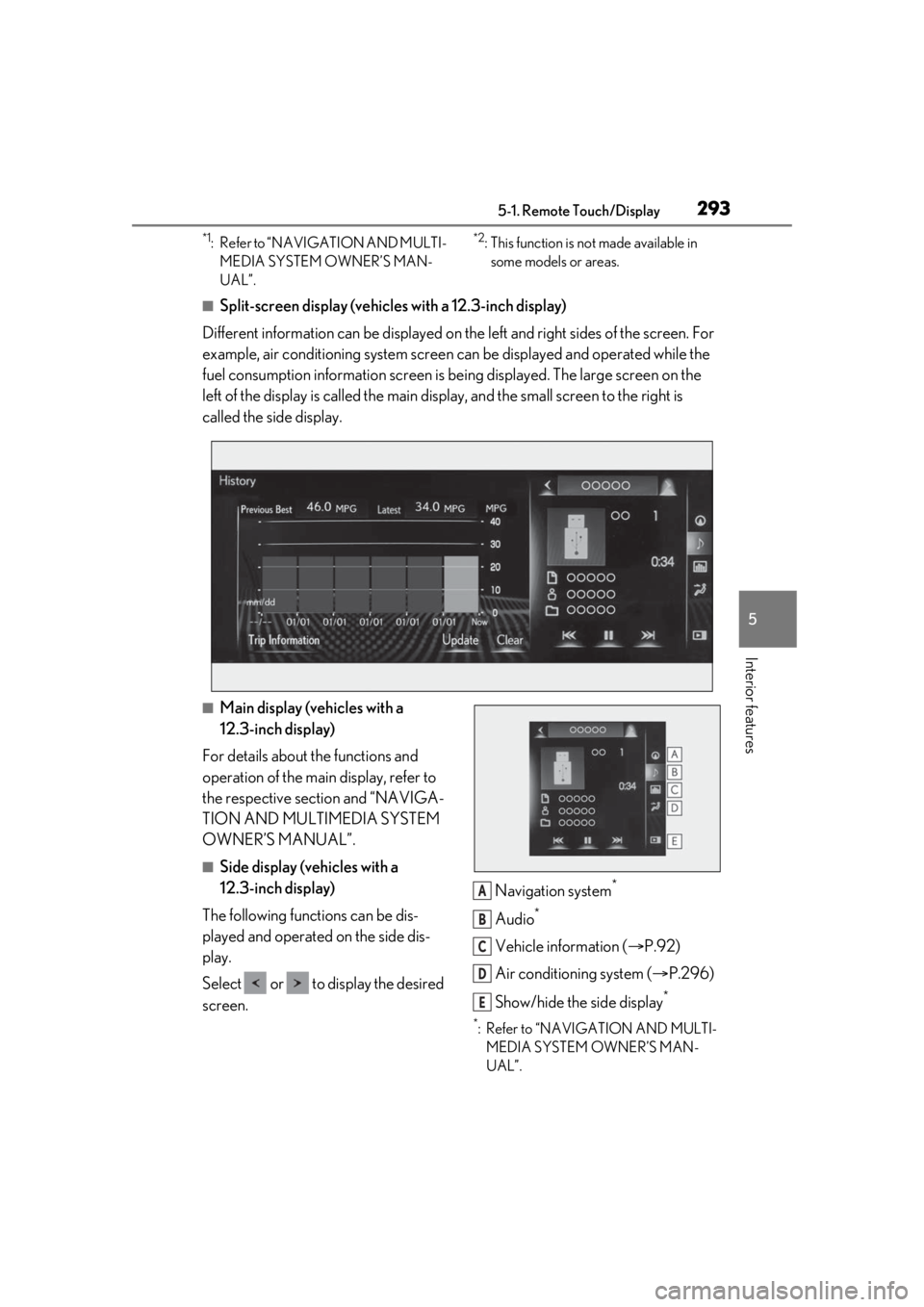
■Split-screen display (vehicles with a 12.3-inch display)
Different information can be displayed on the left and right sides of the screen. For
example, air conditioning system screen can be displayed and operated while the
fuel consumption information screen is be ing displayed. The large screen on the
left of the display is called the main display, and the small screen to the right is
called the side display.
■Main display (vehicles with a
12.3-inch display)
For details about the functions and
operation of the main display, refer to
the respective section and “NAVIGA-
TION AND MULTIMEDIA SYSTEM
OWNER’S MANUAL”.
■Side display (vehicles with a
12.3-inch display)
The following functions can be dis-
played and operated on the side dis-
play.
Select or to display the desired
screen. Navigation system
*
Audio*
Vehicle information (
P.92)
Air conditioning system ( P.296)
Show/hide the side display
*
*: Refer to “NAVIGATION AND MULTI- MEDIA SYSTEM OWNER’S MAN-
UAL”.
A
B
C
D
E
Page 299 of 516
2995-3. Using the air conditioning system and defogger
5
Interior features
push-button start is used to unlock a pas-
senger door.
●The doors that can recall the air condi-
tioning setting when unlocked using the
smart access system with push-button
start can be changed.
* For details, con-
tact your Lexus dealer.
*: The doors that can recall the driving
position memory are changed at the
same time.
■Operation of the air conditioning sys-
tem in Eco drive mode
In Eco drive mode, the air conditioning sys-
tem is controlled as follows to prioritize fuel
efficiency:
●Engine speed and compressor operation
controlled to restri ct heating/cooling
capacity
●Fan speed restricted when automatic
mode is selected
To improve air condit ioning performance,
perform the following operations:
●Adjust the fan speed
●Turn off Eco drive mode ( P.274)
■When the outside temperature falls to
nearly 32°F (0°C)
The dehumidification function may not
operate even when “A/C” is selected.
■Ventilation and air conditioning odors
●To let fresh air in, set the air conditioning
system to the outside air mode.
●During use, various odors from inside and
outside the vehicle may enter into and
accumulate in the air conditioning sys-
tem. This may then cause odor to be
emitted from the vents.
●To reduce potential odors from occur-
ring:
• It is recommended that the air condition- ing system be set to outside air mode
prior to turning the vehicle off.
• The start timing of the blower may be delayed for a short period of time imme-
diately after the air conditioning system is
started in automatic mode or with the
micro dust and pollen filter on.
■Using the voice command system
Air conditioning system can be operated
using voice commands. For details, refer to
“NAVIGATION AND MULTIMEDIA
SYSTEM OWNER’S MANUAL”.
■Air conditioning filter
P.386
■Air conditioning system refrigerant
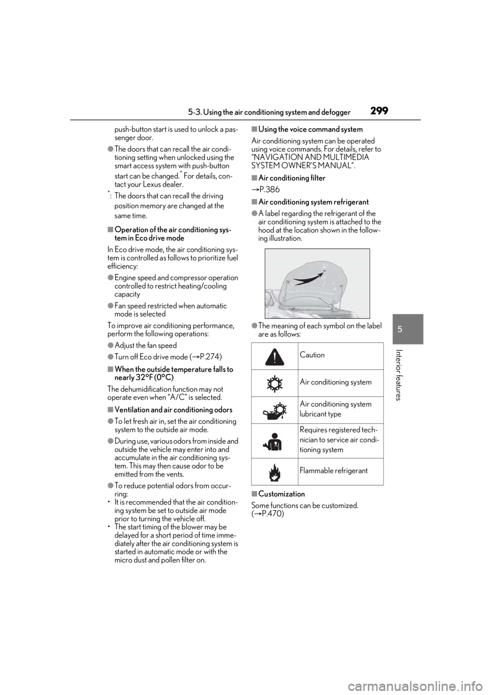
●A label regarding the refrigerant of the
air conditioning system is attached to the
hood at the location shown in the follow-
ing illustration.
●The meaning of each symbol on the label
are as follows:
■Customization
Some functions can be customized.
( P.470)
Caution
Air conditioning system
Air conditioning system
lubricant type
Requires registered tech-
nician to service air condi-
tioning system
Flammable refrigerant
Page 336 of 516
3365-6. Using the other interior features
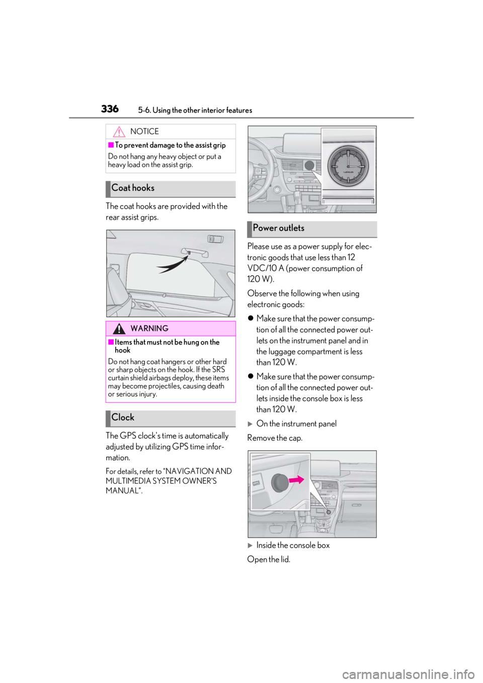
The coat hooks are provided with the
rear assist grips.
The GPS clock's time is automatically
adjusted by utilizing GPS time infor-
mation.
For details, refer to “NAVIGATION AND
MULTIMEDIA SYSTEM OWNER’S
MANUAL”.
Please use as a power supply for elec-
tronic goods that use less than 12
VDC/10 A (power consumption of
120 W).
Observe the following when using
electronic goods:
Make sure that the power consump-
tion of all the connected power out-
lets on the instrument panel and in
the luggage compartment is less
than 120 W.
Make sure that the power consump-
tion of all the connected power out-
lets inside the console box is less
than 120 W.
On the instrument panel
Remove the cap.
Inside the console box
Open the lid.
NOTICE
■To prevent damage to the assist grip
Do not hang any heavy object or put a
heavy load on th e assist grip.
Coat hooks
WARNING
■Items that must not be hung on the
hook
Do not hang coat hangers or other hard
or sharp objects on the hook. If the SRS
curtain shield airbags deploy, these items
may become projectiles, causing death
or serious injury.
Clock
Power outlets
Page 437 of 516
4377-2. Steps to take in an emergency
7
When trouble arises
WARNING
• PCS (Pre-Collision System)
• LTA (Lane Tracing Assist)
• RSA (Road Sign Assist) (if equipped)
•Automatic High Beam
• AFS (Adaptive Front-lighting System) (if equipped)
• Tire pressure warning system
• Intuitive parking assist (if equipped)
• PKSB (Parking Support Brake) (if equipped)
• Lexus parking assist monitor (if equipped)
• Panoramic view monitor (if equipped)
• BSM (Blind Spot Monitor) (if equipped)
• Navigation system (if equipped)
Also, not only can the following system
not be utilized fully, but it may even nega-
tively affect the drive-train components:
• AWD system (AWD models)
■Speed limit when using the compact
spare tire
Do not drive at speeds in excess of 50
mph (80 km/h) when a compact spare
tire is installed on the vehicle.
The compact spare tire is not designed
for driving at high speeds. Failure to
observe this precaution may lead to an
accident causing deat h or serious injury.
■After using the tools and jack
Before driving, make sure all the tools
and jack are securely in place in their
storage location to reduce the possibility
of personal injury during a collision or
sudden braking.
NOTICE
■Be careful when driving over bumps
with the compact spare tire installed
on the vehicle
The vehicle becomes lower when driving
with the compact spar e tire compared to
when driving with standard tires. Be
careful when driving over uneven road
surfaces.
■Driving with tire chains and the com-
pact spare tire
Do not fit tire chains to the compact
spare tire. Tire chains may damage the
vehicle body and adversely affect driving
performance.
■When replacing the tires
When removing or fitting the wheels,
tires or the tire pr essure warning valve
and transmitter, contact your Lexus
dealer as the tire pressure warning valve
and transmitter may be damaged if not
handled correctly.
■When stowing the flat tire (RX350L)
●Ensure that there is no object caught
between the tire and the vehicle
underbody.
●Securely tighten the spare tire clamp
bolt to hold the spare wheel carrier by
the hook.
●Stow the flat tire in the spare tire loca-
tion. Failure to do so may cause dam-
age to the spare tire carrier. Proper
storage reduces the possibility of injury
in a collision or during sudden braking.
●Have the flat tire repaired and the
spare tire replaced with it as soon as
possible.