ECU LEXUS RX450h 2022 Repair Manual
[x] Cancel search | Manufacturer: LEXUS, Model Year: 2022, Model line: RX450h, Model: LEXUS RX450h 2022Pages: 532, PDF Size: 27.62 MB
Page 252 of 532

2504-5. Using the driving support systems
ations:
• When the sensor is misaligned due to a strong impact to the sensor or its sur-
rounding area
• When the distance between your vehicle and a guardrail, wall, etc. that enters the
detection area is short
• When driving up and down consecutive steep inclines, such as hills, dips in the
road, etc.
• When vehicle lanes are narrow, or when driving on the edge of a lane, and a vehi-
cle traveling in a lane other than the adja-
cent lanes enters the detection area
• When driving on roads with sharp bends,
consecutive curves, or uneven surfaces
• When the tires are slipping or spinning
• When the distance between your vehicle and a following vehicle is short
• When an accessory (such as a bicycle carrier) is installed to the rear of the vehi-
cle
*: If equipped
■Intuitive parking assist (if
equipped)
Ultrasonic sensors are used to detect
static objects in the detection area
when driving at a low speed or backing
up. ( P.252)
■RCTA (Rear Cross Traffic Alert)
function (if equipped)
Rear side radar sensors are used to
detect approaching vehicles in the
detection areas behind the vehicle
when backing up. ( P.259)
■Adjusting the buzzer volume
The buzzer volume can be adjusted on
the multi-information display. The vol-
ume of buzzers for the intuitive parking
assist and RCTA function will be
PKSA (Parking Support
Alert)
*
The Parking Support Alert system
consists of the following functions
that operate when driving at a low
speed or backing up, such as when
parking. When the system deter-
mines that the possibility of a colli-
sion with a detected object or such
as a wall is high, a warning operates
to urge the driver to take evasive
action.
PKSA (Parking Support Alert)
system
Setting the buzzer volume
Page 326 of 532
3245-5. Using the storage features
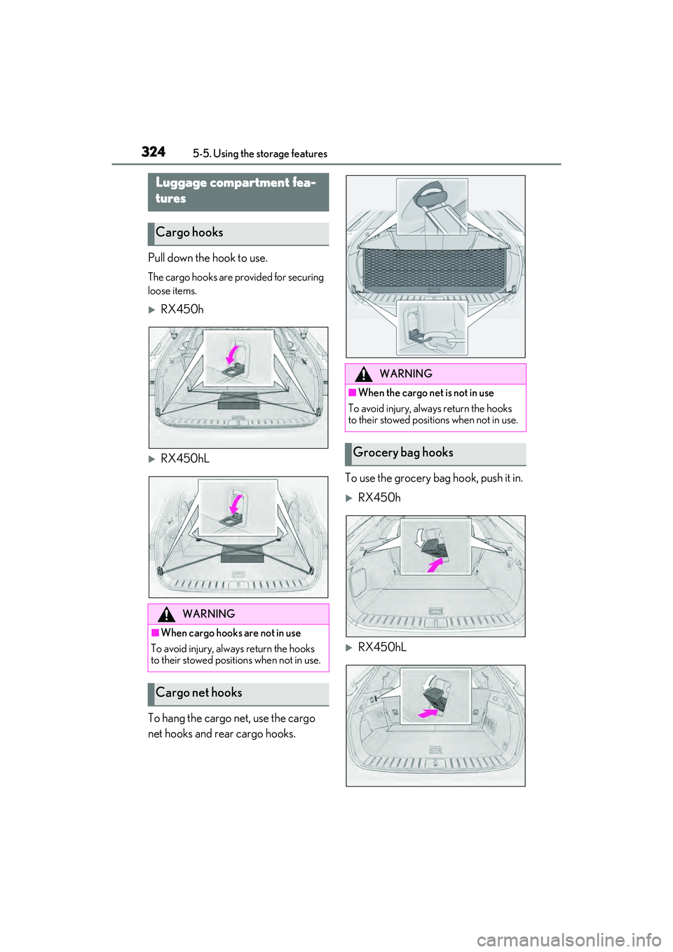
Pull down the hook to use.
The cargo hooks are provided for securing
loose items.
RX450h
RX450hL
To hang the cargo net, use the cargo
net hooks and rear cargo hooks. To use the grocery bag hook, push it in.
RX450h
RX450hL
Luggage compartment fea-
tures
Cargo hooks
WARNING
■When cargo hooks are not in use
To avoid injury, always return the hooks
to their stowed positions when not in use.
Cargo net hooks
WARNING
■When the cargo net is not in use
To avoid injury, always return the hooks
to their stowed positions when not in use.
Grocery bag hooks
Page 343 of 532
3415-6. Using the other interior features
5
Interior features
■HomeLink® programming procedure
The programming procedures can also be
found at the following URL.
Website: www.homelink.com/lexus
For support, contact customer support at
the following.
Help Line: 1-800-355-3515
The HomeLink® wireless control sys-
tem in your vehicle has 3 buttons which
can be programmed to operate 3 dif-
ferent devices. Refer to the program-
ming methods on the following pages
to determine the method which is
appropriate for the device.
NOTICE
■To ensure normal operation of the
sunshade
●Do not put anything in an area where it
may interfere with the operation of a
rear door sunshade.
●To prevent damage to the rear door
sunshades, do no t apply excessive
load or attach items to the rear door
sunshades.
Garage door opener
The garage door opener can be
programmed using the
HomeLink
® to operate garage
doors, gates, entry doors, door
locks, home lighting systems, secu-
rity systems, and other devices.
System components
Page 350 of 532
3485-6. Using the other interior features
2Press and hold the switch for 6 sec-
onds. A number (1 to 15) appears
on the compass display.
3 Press the switch and, referring to
the map above, select the number
of the zone where you are.
If the direction is di splayed several seconds
after adjustment, the calibration is com-
plete.
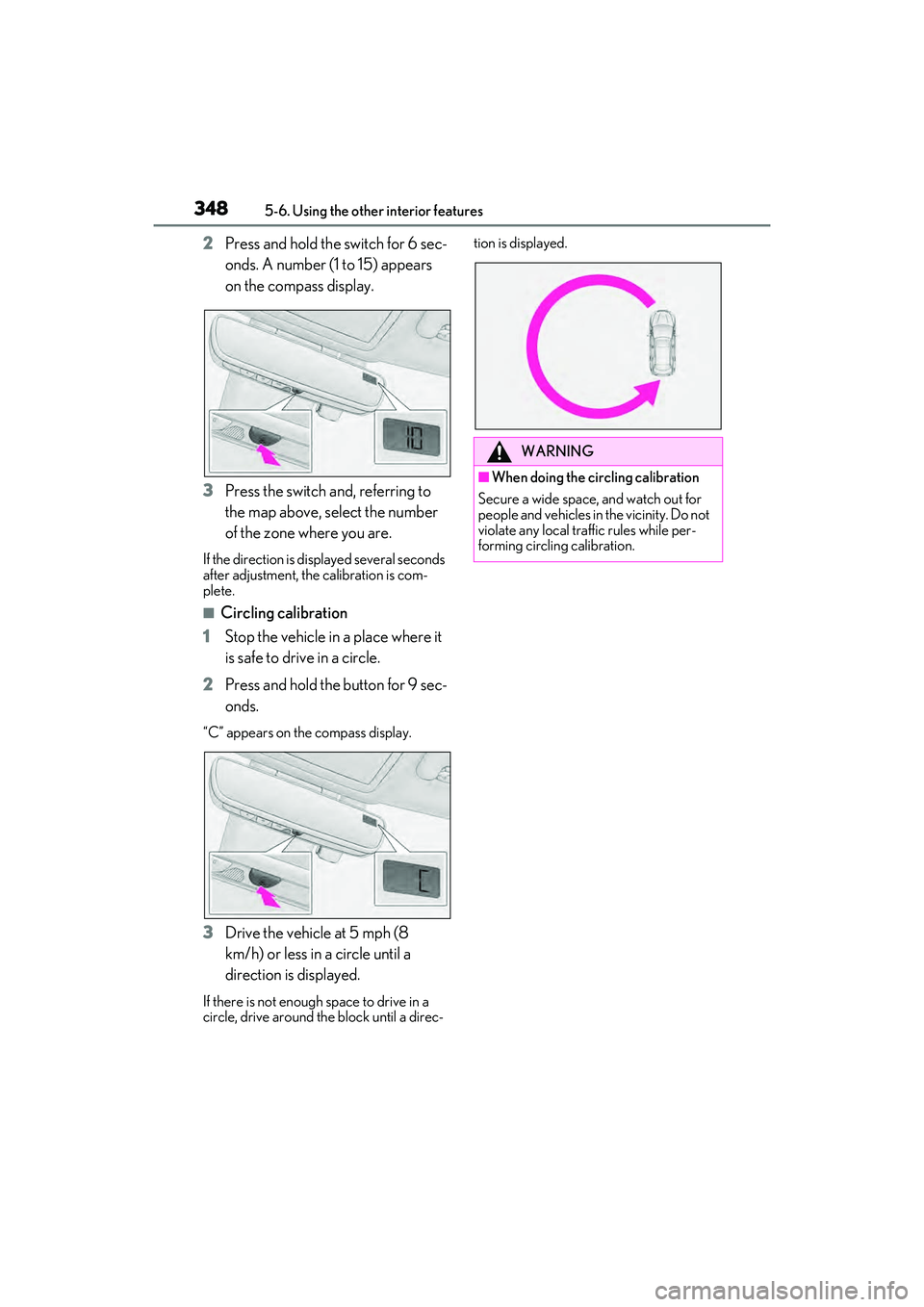
■Circling calibration
1 Stop the vehicle in a place where it
is safe to drive in a circle.
2 Press and hold the button for 9 sec-
onds.
“C” appears on th e compass display.
3Drive the vehicle at 5 mph (8
km/h) or less in a circle until a
direction is displayed.
If there is not enough space to drive in a
circle, drive around the block until a direc- tion is displayed.
WARNING
■When doing the circling calibration
Secure a wide space, and watch out for
people and vehicles in the vicinity. Do not
violate any local traffic rules while per-
forming circling calibration.
Page 360 of 532
3586-2. Maintenance
Radiator/con-
denser
The radiator and con-
denser should be free
from foreign objects.
(P.368)
Washer fluid
Is there sufficient
washer fluid?
(P.369)
Luggage compartment
ItemsCheck points
12-volt batteryCheck the connec-
tions. ( P.370)
Vehicle interior
ItemsCheck points
Accelerator
pedal
• The accelerator
pedal should move
smoothly (without
uneven pedal effort
or catching).
Hybrid transmis-
sion “Park” mech-
anism
•When parked on a slope and the shift
lever is in P, is the
vehicle securely
stopped?
Brake pedal
• Does the brake pedal move
smoothly?
• Does the brake pedal have appro-
priate clearance
from the floor?
• Does the brake pedal have the cor-
rect amount of free
play?
ItemsCheck points
Brakes
• The vehicle should not pull to one side
when the brakes are
applied.
• The brakes should work effectively.
• The brake pedal should not feel
spongy.
• The brake pedal should not get too
close to the floor
when the brakes are
applied.
Head restraints
•Do the head restraints move
smoothly and lock
securely?
Indicators/buzz-
ers•Do the indicators and buzzers function
properly?
Lights
• Do all the lights come on?
• Are the headlights aimed correctly?
( P.390)
Parking brake
•Does the parking
brake switch oper-
ate normally?
• When parked on a slope and the park-
ing brake is on, is the
vehicle securely
stopped?
Seat belts
• Do the seat belts operate smoothly?
• The seat belts should not be damaged.
ItemsCheck points
Page 387 of 532
3856-3. Do-it-yourself maintenance
6
Maintenance and care
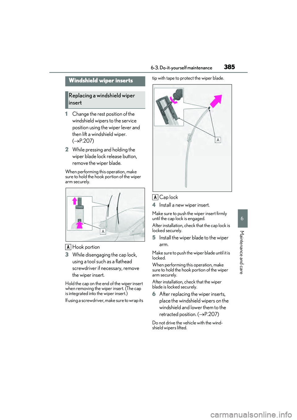
1Change the rest position of the
windshield wipers to the service
position using the wiper lever and
then lift a windshield wiper.
( P.207)
2 While pressing and holding the
wiper blade lock release button,
remove the wiper blade.
When performing this operation, make
sure to hold the hook portion of the wiper
arm securely.
Hook portion
3 While disengaging the cap lock,
using a tool such as a flathead
screwdriver if necessary, remove
the wiper insert.
Hold the cap on the end of the wiper insert
when removing the wiper insert. (The cap
is integrated into the wiper insert.)
If using a screwdriver, make sure to wrap its tip with tape to protect the wiper blade.
Cap lock
4 Install a new wiper insert.
Make sure to push the wiper insert firmly
until the cap lock is engaged.
After installation, check that the cap lock is
locked securely.
5 Install the wiper blade to the wiper
arm.
Make sure to push the wiper blade until it is
locked.
When performing this operation, make
sure to hold the hook portion of the wiper
arm securely.
After installation, check that the wiper
blade is locked securely.
6After replacing the wiper inserts,
place the windshield wipers on the
windshield and lower them to the
retracted position. ( P.207)
Do not drive the vehicle with the wind-
shield wipers lifted.
Windshield wiper inserts
Replacing a windshield wiper
insert
A
A
Page 396 of 532
3946-3. Do-it-yourself maintenance
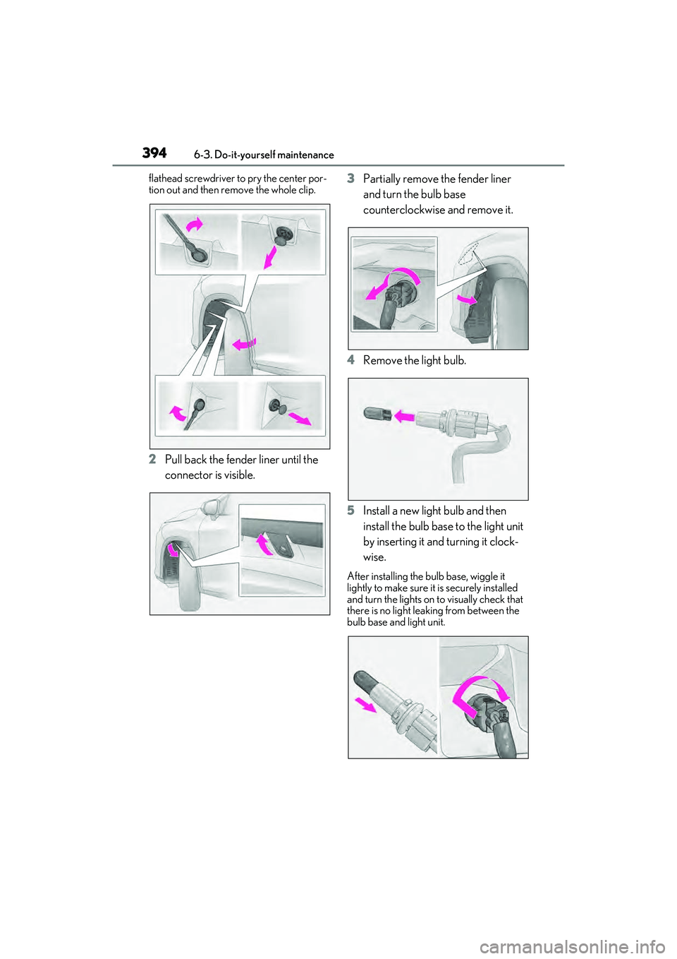
flathead screwdriver to pry the center por-
tion out and then re move the whole clip.
2Pull back the fender liner until the
connector is visible. 3
Partially remove the fender liner
and turn the bulb base
counterclockwise and remove it.
4 Remove the light bulb.
5 Install a new light bulb and then
install the bulb base to the light unit
by inserting it and turning it clock-
wise.
After installing the bulb base, wiggle it
lightly to make sure it is securely installed
and turn the lights on to visually check that
there is no light leaking from between the
bulb base and light unit.
Page 398 of 532
3966-3. Do-it-yourself maintenance
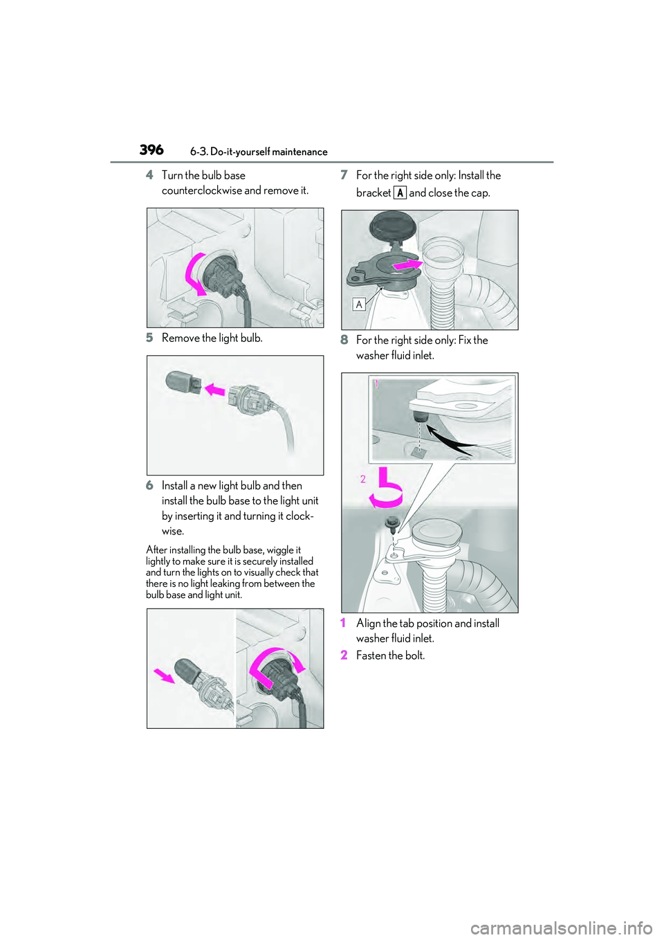
4Turn the bulb base
counterclockwise and remove it.
5 Remove the light bulb.
6 Install a new light bulb and then
install the bulb base to the light unit
by inserting it and turning it clock-
wise.
After installing the bu lb base, wiggle it
lightly to make sure it is securely installed
and turn the lights on to visually check that
there is no light leaking from between the
bulb base and light unit.
7 For the right side only: Install the
bracket and close the cap.
8 For the right side only: Fix the
washer fluid inlet.
1 Align the tab position and install
washer fluid inlet.
2 Fasten the bolt.
A
Page 400 of 532
3986-3. Do-it-yourself maintenance
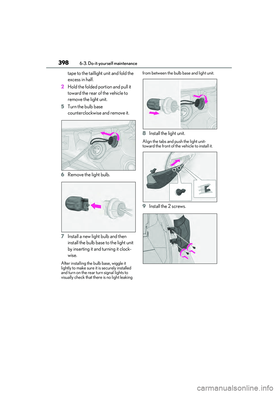
tape to the taillight unit and fold the
excess in half.
2 Hold the folded portion and pull it
toward the rear of the vehicle to
remove the light unit.
5 Turn the bulb base
counterclockwise and remove it.
6 Remove the light bulb.
7 Install a new light bulb and then
install the bulb base to the light unit
by inserting it and turning it clock-
wise.
After installing the bu lb base, wiggle it
lightly to make sure it is securely installed
and turn on the rear turn signal lights to
visually check that there is no light leaking from between the bulb
base and light unit.
8Install the light unit.
Align the tabs and push the light unit-
toward the front of the vehicle to install it.
9Install the 2 screws.
Page 401 of 532
3996-3. Do-it-yourself maintenance
6
Maintenance and care
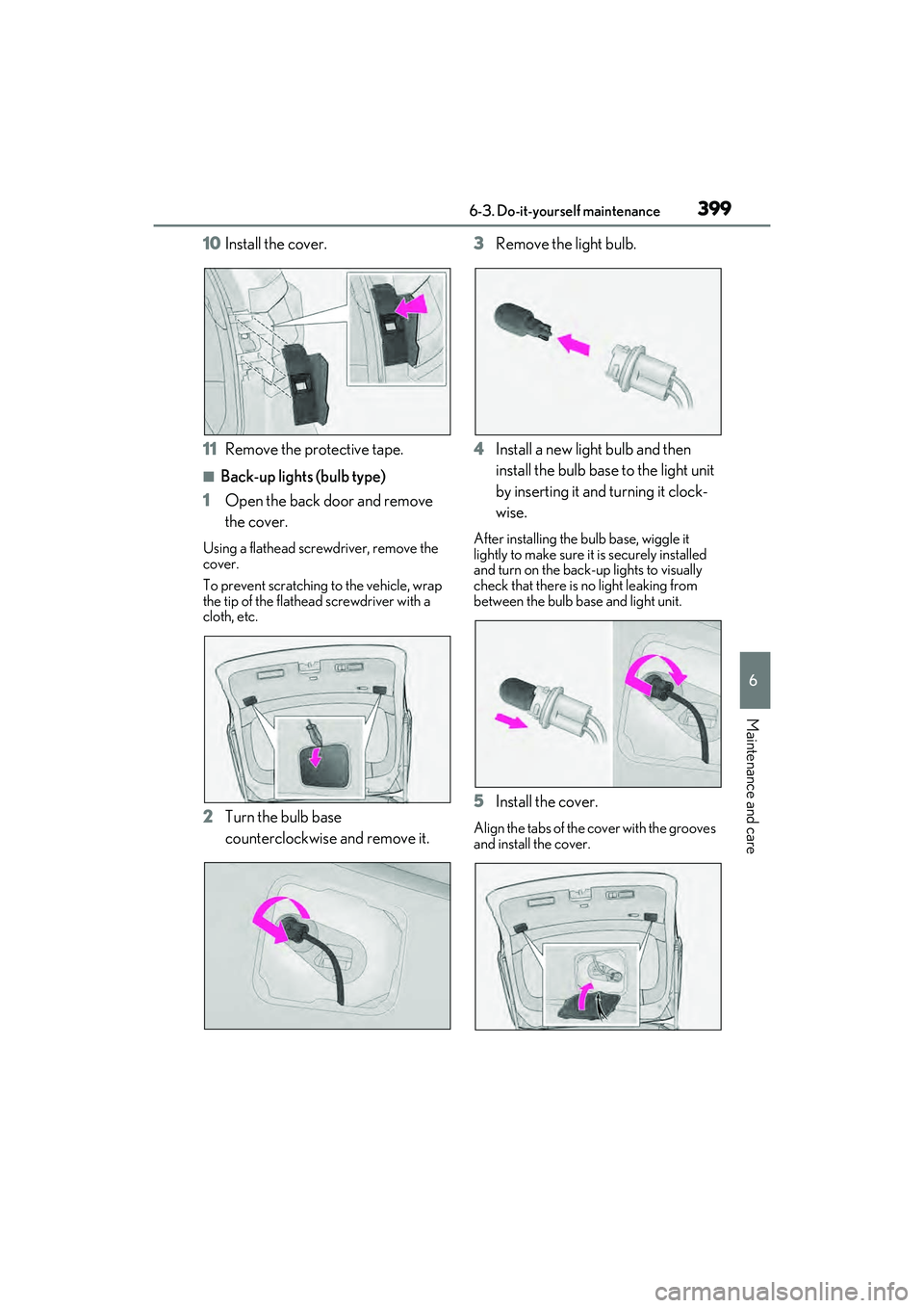
10Install the cover.
11 Remove the protective tape.
■Back-up lights (bulb type)
1 Open the back door and remove
the cover.
Using a flathead scre wdriver, remove the
cover.
To prevent scratching to the vehicle, wrap
the tip of the flathead screwdriver with a
cloth, etc.
2 Turn the bulb base
counterclockwise and remove it. 3
Remove the light bulb.
4 Install a new light bulb and then
install the bulb base to the light unit
by inserting it and turning it clock-
wise.
After installing the bulb base, wiggle it
lightly to make sure it is securely installed
and turn on the back-up lights to visually
check that there is no light leaking from
between the bulb ba se and light unit.
5Install the cover.
Align the tabs of the cover with the grooves
and install the cover.