check LEXUS SC300 1991 Service Repair Manual
[x] Cancel search | Manufacturer: LEXUS, Model Year: 1991, Model line: SC300, Model: LEXUS SC300 1991Pages: 4087, PDF Size: 75.75 MB
Page 3775 of 4087
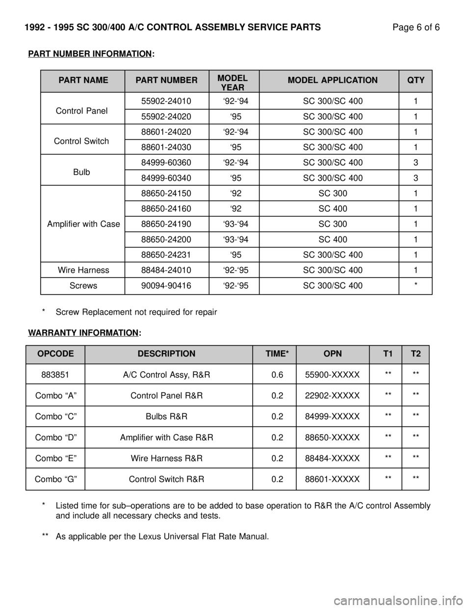
1992 - 1995 SC 300/400 A/C CONTROL ASSEMBLY SERVICE PARTSPage 6 of 6
MODEL
YEAR
Control Panel
Control Switch
Bulb
PART NUMBER INFORMATION:
PART NAME PART NUMBER MODEL APPLICATION QTY 55902-24010 `92-`94 SC 300/SC 400 1
55902-24020 `95 SC 300/SC 400 1
88601-24020 `92-`94 SC 300/SC 400 1
88601-24030 `95 SC 300/SC 400 1
84999-60360 `92-`94 SC 300/SC 400 3
84999-60340 `95 SC 300/SC 400 3
88650-24150 `92 SC 300 1
88650-24160 `92 SC 400 1
Amplifier with Case 88650-24190 `93-`94 SC 300 1
88650-24200 `93-`94 SC 400 1
88650-24231 `95 SC 300/SC 400 1
Wire Harness 88484-24010 `92-`95 SC 300/SC 400 1
Screws 90094-90416 `92-`95 SC 300/SC 400 *
* Screw Replacement not required for repair
WARRANTY INFORMATION
:
OPCODE DESCRIPTION TIME* OPN T1 T2
883851 A/C Control Assy, R&R 0.6 55900-XXXXX ** **
Combo ªAº Control Panel R&R 0.2 22902-XXXXX ** **
Combo ªCº Bulbs R&R 0.2 84999-XXXXX ** **
Combo ªDº Amplifier with Case R&R 0.2 88650-XXXXX ** ** Combo ªEº Wire Harness R&R 0.2 88484-XXXXX ** **
Combo ªGº Control Switch R&R 0.2 88601-XXXXX ** **
* Listed time for sub±operations are to be added to base operation to R\
&R the A/C control Assembly and include all necessary checks and tests.
** As applicable per the Lexus Universal Flat Rate Manual.
WhereEverybodyKnowsYourName
Page 3776 of 4087
TSIB
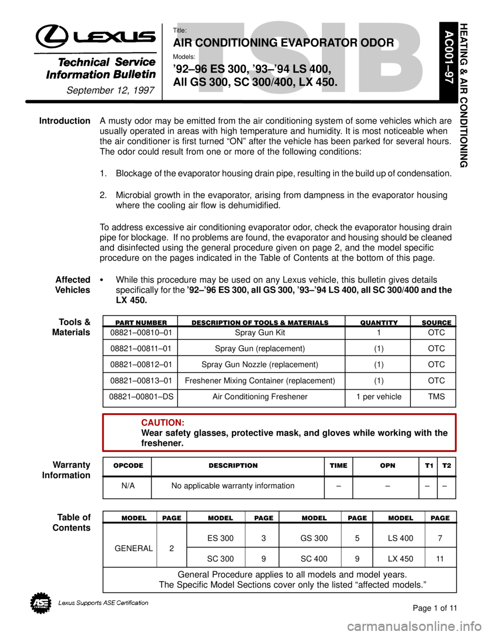
IntroductionA musty odor may be emitted from the air conditioning system of some vehicles which are
usually operated in areas with high temperature and humidity. It is most noticeable when
the air conditioner is first turned ªONº after the vehicle has bee\
n parked for several hours.
The odor could result from one or more of the following conditions:
1. Blockage of the evaporator housing drain pipe, resulting in the build up of cond\
ensation.
2. Microbial growth in the evaporator, arising from dampness in the evaporator housing
where the cooling air flow is dehumidified.
To address excessive air conditioning evaporator odor, check the evaporator housing drain
pipe for blockage. If no problems are found, the evaporator and housing\
should be cleaned
and disinfected using the general procedure given on page 2, and the model \
specific
procedure on the pages indicated in the Table of Contents at the bottom of this page.
Affected While this procedure may be used on any Lexus vehicle, this bulletin giv\
es details
Vehicles specifically for the '92±'96 ES 300, all GS 300, '93±'94 LS 400, all SC 300/400 and the\
LX 450.
Tools &
PART NUMBER DESCRIPTION OF TOOLS & MATERIALS QUANTITY SOURCE
Materials08821±00810±01 Spray Gun Kit 1 OTC 08821±00811±01 Spray Gun (replacement) (1) OTC
08821±00812±01 Spray Gun Nozzle (replacement) (1) OTC
08821±00813±01 Freshener Mixing Container (replacement) (1) OTC
08821±00801±DS Air Conditioning Freshener 1 per vehicle TMS
CAUTION:
Wear safety glasses, protective mask, and gloves while working with the
freshener.
Warranty
OPCODE DESCRIPTION TIME OPN T1 T2
Information
N/A No applicable warranty information ± ± ± ±
Table ofMODEL PAGE MODEL PAGE MODEL PAGE MODEL PAGE
Contents
ES 300 3 GS 300 5 LS 400 7
GENERAL 2
SC 300 9 SC 400 9 LX 450 11
General Procedure applies to all models and model years.
The Specific Model Sections cover only the listed ªaffected models.º
HEATING & AIR CONDITIONING
September 12, 1997
Title:
AIR CONDITIONING EVAPORATOR ODOR
Models:
'92±96 ES 300, '93±'94 LS 400,
All GS 300, SC 300/400, LX 450.
Page 1 of 11
AC001±97
WhereEverybodyKnowsYourName
Page 3807 of 4087
CHANGE IN SUPPLY PARTS FOR INNER REAR VIEW MIRROR (CONT'D)Page 3 of 3
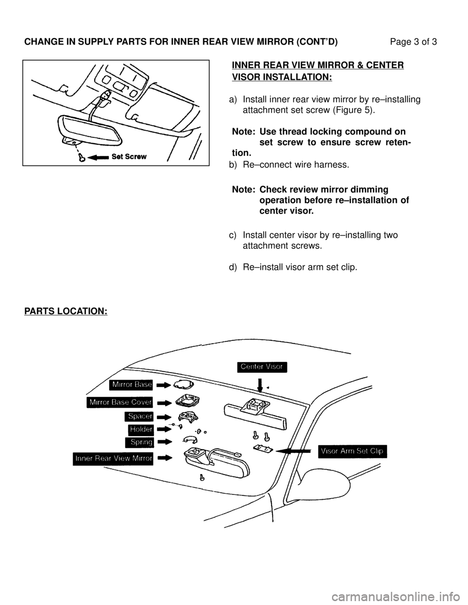
a) Install inner rear view mirror by re±installing
attachment set screw (Figure 5).
INNER REAR VIEW MIRROR & CENTER
VISOR INSTALLATION:
PARTS LOCATION:
Note: Use thread locking compound on
set screw to ensure screw reten-
tion.
b) Re±connect wire harness.
Note: Check review mirror dimming operation before re±installation of
center visor.
c) Install center visor by re±installing two attachment screws.
d) Re±install visor arm set clip.
WhereEverybodyKnowsYourName
Page 3810 of 4087

SERVICE HINTS FOR REFRIGERANT LEAK DETECTIONPage 1 of 3
Use of electronic leak detectors for checking A/C systems refrigerant leaka\
ge is the only
method approved by TMS. This type of leak detector is sensitive not onl\
y to refrigerant, but
also sensitive to numerous petrochemical substances (motor oil, gasolin\
e, solvents, etc.)
commonly found in a repair shop environment. Because this sensitivity c\
ould diminish the leak
detector 's capacity for accurate leak detection, some service hints have been pro\
vided to help
increase the accuracy of your diagnosis.
SERVICE HINTS:
1. Visual Inspection: Do a quick visual inspection under the hood for signs of refrigerant
leakage. Check for areas of heavy oil leakage at block and piping joint\
s. Many times
these areas have accumulated road dust and dirt.
2. Inspection with leak detector: NOTE: Make sure the system is fully charged. Operate
the system to increase refrigerant pressure. Shut the system off before inspecting with
leak detector.
A. Checking for leakage at a joint:
Wipe the oil/dirt accumulation off the joint with a
clean rag. Do not use solvents to clean the joint. Refrigerant is heavi\
er than air so
start checking for leaks with the detector wand about 1/4 in. below the \
joint. Move the
wand slowly across and around each joint (see illustration below).
Piping Joint Move detector wand slowly across
and around each joint.
Block Joint
HEATING &
AIR CONDITIONING
AC95±001
MARCH 03, 1995
ALL MODELS
WhereEverybodyKnowsYourName
Page 3811 of 4087
SERVICE HINTS FOR REFRIGERANT LEAK DETECTIONPage 2 of 3
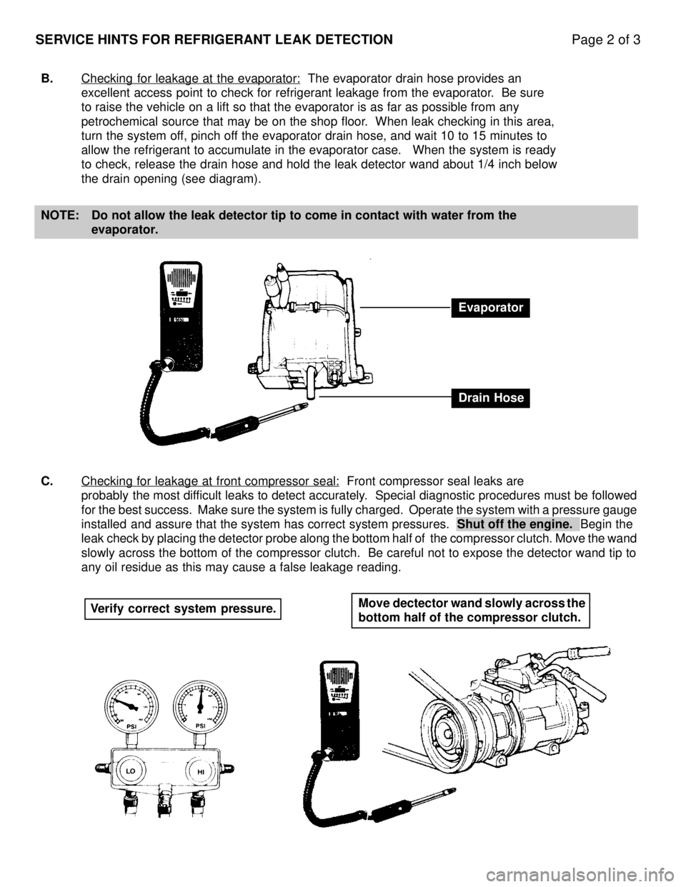
B.Checking for leakage at the evaporator: The evaporator drain hose provides an
excellent access point to check for refrigerant leakage from the evapora\
tor. Be sure
to raise the vehicle on a lift so that the evaporator is as far as possi\
ble from any
petrochemical source that may be on the shop floor. When leak checking in this area,
turn the system off, pinch off the evaporator drain hose, and wait 10 to 15 minutes to
allow the refrigerant to accumulate in the evaporator case. When the s\
ystem is ready
to check, release the drain hose and hold the leak detector wand about 1\
/4 inch below
the drain opening (see diagram).
NOTE: Do not allow the leak detector tip to come in contact with water from th\
e evaporator.
C. Checking for leakage at front compressor seal:
Front compressor seal leaks are
probably the most difficult leaks to detect accurately. Special diagnostic procedures must be followed
for the best success. Make sure the system is fully charged. Operate the \
system with a pressure gauge
installed and assure that the system has correct system pressures. Shut off the engine. Begin the
leak check by placing the detector probe along the bottom half of the compr\
essor clutch. Move the wand
slowly across the bottom of the compressor clutch. Be careful not to expose t\
he detector wand tip to
any oil residue as this may cause a false leakage reading.
Evaporator
Drain Hose
Verify correct system pressure. Move dectector wand slowly across the
bottom half of the compressor clutch.
WhereEverybodyKnowsYourName
Page 3812 of 4087

SERVICE HINTS FOR REFRIGERANT LEAK DETECTIONPage 3 of 3
D. Checking for leakage at service valves or pressure switches:
Small accumulations of refrigerant gas under the service valve caps or p\
ressure switch connectors is
normal. When checking for leaks at these points, use the following proc\
edures to assure the highest
accuracy:
1. Remove the service valve cap or pressure switch connector.
2. Allow the service valve or pressure switch to remain uncapped for approx\
imately
20 minutes. This will allow the air to circulate and carry away the acc\
umulated
refrigerant. (This is a good time to leak check other areas of the syst\
em).
3. Do not use compressed air to flush out the service valve or pressure swi\
tch
cavity. Petroleum residue from inline oilers or compressor lubrication may ca\
use
false readings.
WhereEverybodyKnowsYourName
Page 3816 of 4087
SUSPENSION BALL JOINT INSPECTION ± PG012-02 October 11, 2002
Page 3 of 5
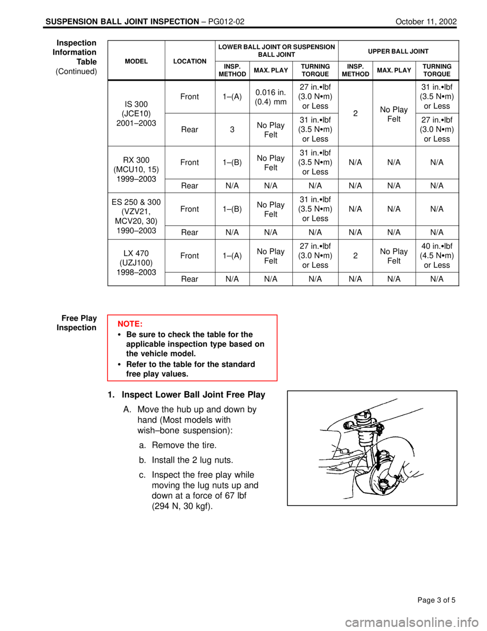
MODELLOCATION
LOWER BALL JOINT OR SUSPENSION
BALL JOINTUPPER BALL JOINT
MODELLOCATIONINSP.
METHODMAX. PLAYTURNING TORQUEINSP.
METHODMAX. PLAYTURNING TORQUE
IS 300
(JCE10)
Front1±(A)0.016 in.
(0.4) mm27 in. lbf
(3.0 N m)
or Less
2No Play
31 in. lbf
(3.5 N m)
or Less
(JCE10)
2001±2003
Rear3No Play Felt31 in. lbf
(3.5 N m)
or Less2No Play
Felt27 in. lbf
(3.0 N m)
or Less
RX 300
(MCU10, 15)
1999 2003
Front1±(B)No Play Felt31 in. lbf
(3.5 N m)
or Less
N/AN/AN/A
1999±2003RearN/AN/AN/AN/AN/AN/A
ES 250 & 300 (VZV21,
MCV20, 30)Front1±(B)No Play Felt31 in. lbf
(3.5 N m)
or Less
N/AN/AN/A
MCV20, 30)
1990±2003RearN/AN/AN/AN/AN/AN/A
LX 470
(UZJ100)
1998 2003
Front1±(A)No Play Felt27 in. lbf
(3.0 N m)
or Less
2No Play Felt40 in. lbf
(4.5 N m)
or Less
1998±2003RearN/AN/AN/AN/AN/AN/A
NOTE:
Be sure to check the table for the
applicable inspection type based on
the vehicle model.
Refer to the table for the standard
free play values.
1. Inspect Lower Ball Joint Free Play
A. Move the hub up and down byhand (Most models with
wish±bone suspension):
a. Remove the tire.
b. Install the 2 lug nuts.
c. Inspect the free play while moving the lug nuts up and
down at a force of 67 lbf
(294 N, 30 kgf).
Inspection
Information
Table
(Continued)
Free Play
Inspection
WhereEverybodyKnowsYourName
Page 3817 of 4087
SUSPENSION BALL JOINT INSPECTION ± PG012-02 October 11, 2002
Page 4 of 5
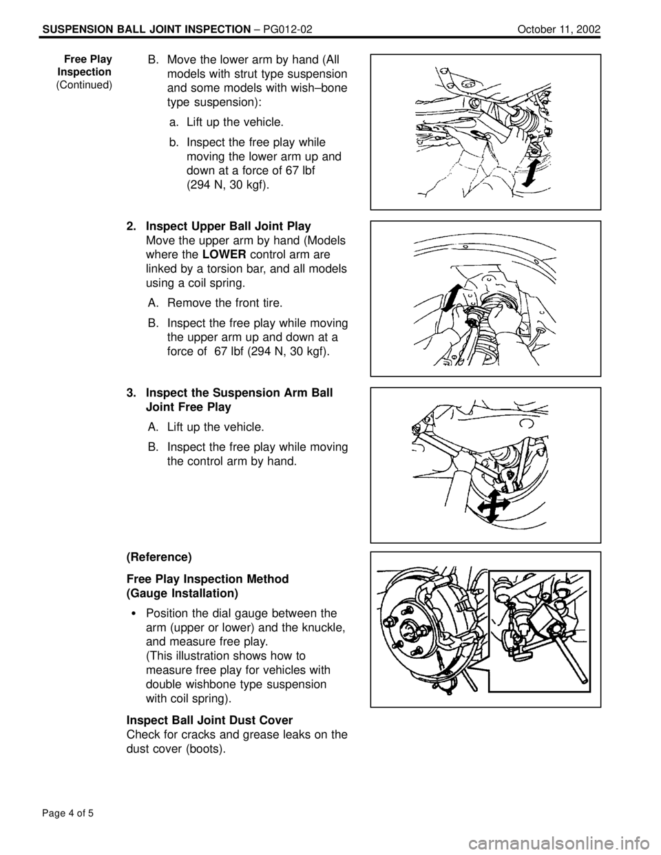
B. Move the lower arm by hand (All
models with strut type suspension
and some models with wish±bone
type suspension):
a. Lift up the vehicle.
b. Inspect the free play while moving the lower arm up and
down at a force of 67 lbf
(294 N, 30 kgf).
2. Inspect Upper Ball Joint Play Move the upper arm by hand (Models
where the LOWER control arm are
linked by a torsion bar, and all models
using a coil spring.
A. Remove the front tire.
B. Inspect the free play while moving the upper arm up and down at a
force of 67 lbf (294 N, 30 kgf).
3. Inspect the Suspension Arm Ball Joint Free Play
A. Lift up the vehicle.
B. Inspect the free play while moving the control arm by hand.
(Reference)
Free Play Inspection Method
(Gauge Installation) Position the dial gauge between the
arm (upper or lower) and the knuckle,
and measure free play.
(This illustration shows how to
measure free play for vehicles with
double wishbone type suspension
with coil spring).
Inspect Ball Joint Dust Cover
Check for cracks and grease leaks on the
dust cover (boots).Free Play
Inspection
(Continued)
WhereEverybodyKnowsYourName
Page 3826 of 4087
15
ABBREVIATIONS
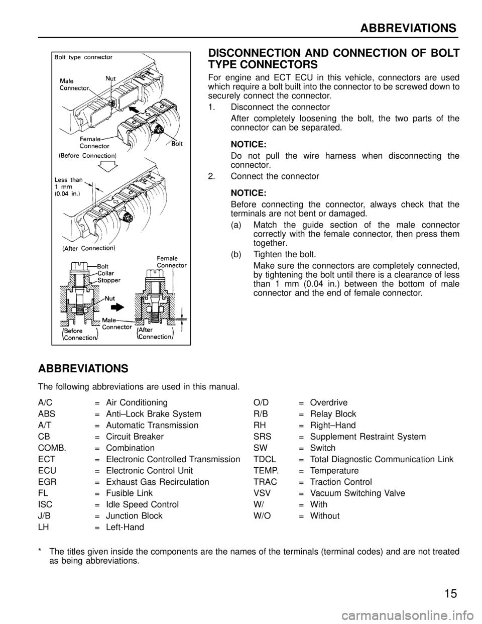
DISCONNECTION AND CONNECTION OF BOLT
TYPE CONNECTORS
For engine and ECT ECU in this vehicle, connectors are used
which require a bolt built into the connector to be screwed down to
securely connect the connector.
1. Disconnect the connectorAfter completely loosening the bolt, the two parts of the
connector can be separated.
NOTICE:
Do not pull the wire harness when disconnecting the
connector.
2. Connect the connector
NOTICE:
Before connecting the connector, always check that the
terminals are not bent or damaged.
(a) Match the guide section of the male connectorcorrectly with the female connector, then press them
together.
(b) Tighten the bolt. Make sure the connectors are completely connected,
by tightening the bolt until there is a clearance of less
than 1 mm (0.04 in.) between the bottom of male
connector and the end of female connector.
ABBREVIATIONS
The following abbreviations are used in this manual.
A/C = Air Conditioning O/D = Overdrive
ABS = Anti±Lock Brake System R/B = Relay Block
A/T = Automatic Transmission RH = Right±Hand
CB = Circuit Breaker SRS = Supplement Restraint System
COMB. = Combination SW = Switch
ECT = Electronic Controlled Transmission TDCL = Total Diagnostic Communication Link
ECU = Electronic Control Unit TEMP. = Temperature
EGR = Exhaust Gas Recirculation TRAC = Traction Control
FL = Fusible Link VSV = Vacuum Switching Valve
ISC = Idle Speed Control W/ = With
J/B = Junction Block W/O = Without
LH = Left-Hand
* The titles given inside the components are the names of the terminals (ter\
minal codes) and are not treatedas being abbreviations.
WhereEverybodyKnowsYourName
Page 3828 of 4087
144
ABS (ANTI±LOCK BRAKE SYSTEM)
M
A
11
MR A
4
R± A
5
SR
A
6 SFL
A
12 SRR
A
8 AST
A
9 MT
B
1 SFR
B
16 PKB
B
2 GND
B
13 GND
B
1B 4 B
3B 2B5
A 4
A 3
A 1 2 1
IG1
19
IO1
5IO1 7
EB EA 16 22 23 11
EB1
6IK1 10
IJ
EA 1
34
3 2
16
1
4
2
IK2
25 IK2 2
IE1
1
IE2
12
2 1
E10
I23I25
E9
2
6 6
666
66
66
6
B
10
WA
B
6
TS
5
6
E12 L
P±B
V±Y
L±W
L±W L
W
V±YL
W± B L±W V±YY±L
R
R
R
B±R
B±R
B±R
P±B
V
L
L
L V
L V±Y
V
R±Y
Y
B±Y P
L±W Y±G
R±W R±W
W±B
W±B
R±W
R±W
B
B
W±B
W±B W±B
W±B W±B
L±WL
W± B
SFR SFL SRR AST MT
BS
BM
GND WA
TS TC
WB
BATTERY ABS ECU
(
W/O TRACTION CONTROL )
R
120A ALT
60A ABS NO. 1
ABS MOTOR
RELAY
ABS ACTUATOR
RELAY
CHECK
CONNECTOR
FUSE BLOCK
R±W
DIODE
(FOR PARKING BRAKE )
BRAKE FLUID
LEVEL SW
PARKING
BRAKE
SW
ABS ACTUATOR
(
CANA DA )
( USA )
B1
D2
A4 , A33
P3
A2 2
,A23
B
BA A
C3
F9 SHORT PIN
WhereEverybodyKnowsYourName